NASA/TR-2004-212819
Product-oriented Software Certification Process for Software Synthesis Stacy Nelson
February 2004
The NASA STI Program Office . . . in Profile
Since its founding, NASA has been dedicated to the advancement of aeronautics and space science. The NASA Scientific and Technical Information (STI) Program Office plays a key part in helping NASA maintain this important role. The NASA STI Program Office is operated by Langley Research Center, the Lead Center for NASA’s scientific and technical information. The NASA STI Program Office provides access to the NASA STI Database, the largest collection of aeronautical and space science STI in the world. The Program Office is also NASA’s institutional mechanism for disseminating the results of its research and development activities. These results are published by NASA in the NASA STI Report Series, which includes the following report types: • TECHNICAL PUBLICATION. Reports of completed research or a major significant phase of research that present the results of NASA programs and include extensive data or theoretical analysis. Includes compilations of significant scientific and technical data and information deemed to be of continuing reference value. NASA’s counterpart of peer-reviewed formal professional papers but has less stringent limitations on manuscript length and extent of graphic presentations. • TECHNICAL MEMORANDUM. Scientific and technical findings that are preliminary or of specialized interest, e.g., quick release reports, working papers, and bibliographies that contain minimal annotation. Does not contain extensive analysis. • CONTRACTOR REPORT. Scientific and technical findings by NASA-sponsored contractors and grantees.
• CONFERENCE PUBLICATION. Collected papers from scientific and technical conferences, symposia, seminars, or other meetings sponsored or cosponsored by NASA. • SPECIAL PUBLICATION. Scientific, technical, or historical information from NASA programs, projects, and missions, often concerned with subjects having substantial public interest. • TECHNICAL TRANSLATION. Englishlanguage translations of foreign scientific and technical material pertinent to NASA’s mission. Specialized services that complement the STI Program Office’s diverse offerings include creating custom thesauri, building customized databases, organizing and publishing research results . . . even providing videos. For more information about the NASA STI Program Office, see the following: • Access the NASA STI Program Home Page at http://www.sti.nasa.gov • E-mail your question via the Internet to
[email protected] • Fax your question to the NASA Access Help Desk at (301) 621-0134 • Telephone the NASA Access Help Desk at (301) 621-0390 • Write to: NASA Access Help Desk NASA Center for AeroSpace Information 7121 Standard Drive Hanover, MD 21076-1320
NASA/TR-2004-212819
Product-oriented Software Certification Process for Software Synthesis Stacy Nelson Ames Research Center, Moffett Field, California
National Aeronautics and Space Administration Ames Research Center Moffett Field, California 94035-1000
February 2004
Available from: NASA Center for AeroSpace Information 7121 Standard Drive Hanover, MD 21076-1320 (301) 621-0390
National Technical Information Service 5285 Port Royal Road Springfield, VA 22161 (703) 487-4650
Product-oriented Software Certification Process for Software Synthesis
FOR
NASA Ames Research Center
Dated: September 25, 2003 Contributors (in alphabetical order by first name): Stacy Nelson, Nelson Consulting (POC) Bernd Fischer, RIACS Ewen Denney, QSS Johann Schumann, RIACS Julian Richardson, RIACS Phil Oh, RIACS
Product-oriented Software Certification Process for Software Synthesis
Page 2
TABLE OF CONTENTS 1. 2.
EXECUTIVE SUMMARY...................................................................................................................... 5 INTRODUCTION .................................................................................................................................. 6 2.1. Certifiable Software Synthesis..................................................................................................... 6 2.2. Other Standards Promoting Formal Proofs ................................................................................. 7 2.2.1. Canadian Nuclear Power Industry: CE-1001-STD ............................................................ 7 2.2.2. European Defence Industry: DEF STAN 00-55 ................................................................. 8 2.2.3. European Transportation Industry: EN 50128 ................................................................... 9 2.3. Traditional Process-Oriented Certification................................................................................. 11 2.4. Safety Case ............................................................................................................................... 11 2.5. Underwriter’s Laboratory (UL) Product-Oriented Approach ...................................................... 12 2.6. Product-oriented versus Process-oriented Approach................................................................ 12 3. PRODUCT-ORIENTED LIFE CYCLE ................................................................................................ 13 3.1. Typical Process-Oriented Life Cycle ......................................................................................... 14 3.1.1. System Requirements....................................................................................................... 14 3.1.2. System Architectural Design............................................................................................. 15 3.1.3. Software Requirements Analysis ...................................................................................... 15 3.1.4. Software Architectural Design........................................................................................... 15 3.1.5. Software Detailed Design ................................................................................................. 15 3.1.6. Software Coding................................................................................................................15 3.1.7. Software Unit Testing........................................................................................................ 16 3.1.8. Software Integration .......................................................................................................... 16 3.1.9. Software Qualification ....................................................................................................... 16 3.1.10. System Integration ............................................................................................................ 16 3.1.11. System Qualification Testing ............................................................................................ 16 3.2. Proposed Product-Oriented Life Cycle ...................................................................................... 17 4. PRODUCT-ORIENTED SAFETY CASE ............................................................................................ 19 5. APPROVAL PROCESS ..................................................................................................................... 20 6. TOOLS ............................................................................................................................................... 22 6.1. For more information ................................................................................................................. 24 6.2. How Synthesis Tools Compare To Traditional V&V Tools ........................................................ 26 6.2.1. Coverage........................................................................................................................... 26 6.2.2. Other testing strategies..................................................................................................... 26 6.3. Certification of Synthesis Tools ................................................................................................. 27 7. ARTIFACTS........................................................................................................................................ 28 8. APPENDIX A: ACRONYMS .............................................................................................................. 30 9. APPENDIX B: GLOSSARY ............................................................................................................... 31 10. APPENDIX C: SAMPLE SYNTHESIZED SDD............................................................................. 32 10.1. Software Design Document ....................................................................................................... 32 10.1.1. Summary........................................................................................................................... 32 10.1.2. Input Specification............................................................................................................. 32 10.1.2.1. Textual Input Specification ....................................................................................... 32 11. APPENDIX D: COMPARISON OF SYNTHESIZED SDD TO STANDARDS ............................... 37 11.1. MIL STD 498.............................................................................................................................. 38 11.1.1. Conclusions....................................................................................................................... 38 11.1.2. Recommendations ............................................................................................................ 38 11.2. IEEE 12207................................................................................................................................ 39 11.2.1. Conclusions....................................................................................................................... 39 11.2.2. Recommendations ............................................................................................................ 39 11.3. DO-178B .................................................................................................................................... 39 11.3.1. Conclusions....................................................................................................................... 39 11.3.2. Recommendations ............................................................................................................ 39
September 25, 2003
Product-oriented Software Certification Process for Software Synthesis
Page 3
12. APPENDIX E: SAFETY DOCUMENT GENERATOR................................................................... 40 12.1. SAFETY EXPLANATIONS ........................................................................................................ 41 13. REFERENCES............................................................................................................................... 43
September 25, 2003
Product-oriented Software Certification Process for Software Synthesis
Page 4
RECORD OF REVISIONS REVISION
DATE
Initial Delivery
8/15/03
All Sections
Draft for review
Update
9/25/03
Sections 2.5 and 2.6
Version 1.0 finished
September 25, 2003
SECTIONS INVOLVED
COMMENTS
Product-oriented Software Certification Process for Software Synthesis
Page 5
1. EXECUTIVE SUMMARY The purpose of this document is to propose a product-oriented software certification process to facilitate use of software synthesis and formal methods. Why is such a process needed? Currently, software is tested until deemed bug-free rather than proving that certain software properties exist. This approach has worked well in most cases, but unfortunately, deaths still occur due to software failure. Using formal methods (techniques from logic and discrete mathematics like set theory, automata theory and formal logic as opposed to continuous mathematics like calculus) and software synthesis, it is possible to reduce this risk by proving certain software properties. Additionally, software synthesis makes it possible to automate some phases of the traditional software development life cycle resulting in a more streamlined and accurate development process. The product-oriented approach views software components like individual units that can be certified similar to the Underwriter’s Laboratory (UL) certification for tangible products, like fireproof doors. To certify that a door is fireproof, UL provides specifications for building a fireproof door then tests the door to ensure it meets these specifications. If the door passes the test, then it is certified as fireproof. While this approach is similar to the traditional software development process, it differs in one important way: the door has been proven to be fireproof, not merely tested until it is believed to be fireproof. Properties of software components can be tested and certified in the same manner. The NASA Automated Software Engineering (ASE) team has developed techniques and tools, called software synthesis, to check the software components using a process similar to Underwriter’s Laboratory certification process. NASA ASE provides guidelines for building formal specifications. Then, using these formal specifications, special tools generate the software and attempt to prove, via mathematical means, that a property has been satisfied. If the software properties can be proven mathematically, then it is deemed to be certified and the safety analysis based on the mathematical proof becomes the certificate. In order to explain the details of the proposed product-oriented certification process, this document contains the following sections: •
Introduction – contains the definition and rationale for product-oriented software certification including an overview of software synthesis. Also, discusses industry standards based on formal proofs and the benefits of the product-oriented approach versus a traditional process-oriented approach.
•
Product-oriented life cycle – includes a review of the traditional software life cycle and description of the new product-oriented life cycle. The new product-oriented life cycle describes automation of some life cycle phases for software components meeting synthesis criteria. These automated techniques can also reduce development costs because they can replace an infinite amount of testing by proving that properties are correct.
•
Product-oriented safety case – compares the traditional safety justification (called a “Safety Case”) to a product-oriented safety justification
•
Approval/Certification Process - reviews the rationale behind traditional Test Readiness Review (TRR), Flight Readiness Review (FRR) and Approval/Certification Decision making. Explains how product-oriented certification can streamline the decision making process and provide greater degree of safety assurance with lower development costs.
•
Tools – describes tools to accomplish product-oriented certification including a description of software synthesis tools, comparison of synthesis to traditional V&V tools and a discussion of certification of synthesis tools.
•
Artifacts - lists proposed artifacts and/or enhancements to traditional artifacts for product-oriented software certification, including automation of the production of the Software Design Document to improve accuracy of design while reducing development costs.
September 25, 2003
Product-oriented Software Certification Process for Software Synthesis
Page 6
2. INTRODUCTION Safety is a property of a system/software meaning that the system/software will not endanger human life or the environment. Safety-critical means that failure or design error could cause a risk to human life. Examples of safety-critical software can be found in nuclear reactors, automobiles, chemical plants, aircraft, spacecraft, et al. Mission critical means the potential loss of capability leading to possible reduction in mission effectiveness1 Examples of mission critical software can be found in unmanned space missions like Deep Space One and others. Certification is the recognition by the certification authority that a software product complies with the requirements2. In the case of tangible items like a fireproof door, the Underwriter’s Laboratory has a certification process whereby the door (having been built to a particular specification) is then torched (also of particular specification). If the door remains intact and doesn’t burn, then it is certified as being fireproof. Historically, software certification has been more complex and risky than certification of fireproof doors. Traditional methods involve review of artifacts to ascertain that the humans constructing the software have sufficient expertise and checks and balances to ensure safety. Generally, there is no proof that software is accurate, but rather an exhaustive (or as exhaustive as the budget allows) effort to find and remove anomalies (bugs). For safety-critical software, a product-oriented approach like that used by UL would make it possible for software reviewers to rely upon proof that software is accurate rather than just trusting it is bug-free. However, until recently, this type of product-oriented certification was too time-consuming and expensive because it required highly skilled mathematicians. Fortunately, the NASA Automated Software Engineering group devised a way to automate these proofs. It is called software synthesis and automated analysis. Using software synthesis, it becomes increasingly more feasible to certify software components using a process similar to UL fireproof door certification. The following section contains an overview of software synthesis. Subsequent sections describe nuclear power, defense and transportation industry standards supporting formal proofs. There is a discussion about the rationale for traditional certification techniques and an explanation of the Underwriter’s Laboratory product-oriented certification technique. Finally, the benefits of the product-oriented approach over the traditional process-oriented approach are identified along with new software development artifacts and enhancements to traditional artifacts.
2.1.
Certifiable Software Synthesis
Software synthesis is a technique for establishing that software is safe based on mathematical proofs. By adding special assertions to code, it is possible to analyze the code and produce a mathematical proof of correctness. This proof is then sent to a proof checker which says “yes” the proof is correct or “no” it is not. At NASA, this technique has been automated so that it occurs quickly and accurately. For purposes of certification, a certificate is a safety explanation of the mathematical proof such as the example in Appendix E.3
September 25, 2003
Product-oriented Software Certification Process for Software Synthesis
Page 7
Sample Specification
Figure 1: Software Synthesis
2.2.
Other Standards Promoting Formal Proofs
The following standards support a product-oriented approach that relies upon formal methods including use of formal proofs: •
CE-1001-STD Rev. 1, Standard for Software Engineering of Safety-Critical Software, CANDU Computer Systems Engineering Centre for Excellence, January 1996 – used in Canada’s Nuclear Power Industry
•
DEF STAN 00-55, Requirements for Safety Related Software in Defence Equipment Part 1: Requirements and Part 2: Guidance, U.K. Ministry of Defence
•
EN (European Norms) 50128:1997, Railway Applications: Software for Railway Control and Protection Systems, the European committee for Electrotechnical Standardisation (CENELEC)
2.2.1.
Canadian Nuclear Power Industry: CE-1001-STD
Adopted in 1990, CE-1001-STD Rev. 1 focuses on three categories of safety systems in a nuclear power plant: shutdown systems, emergency coolant injection systems and nuclear generating containment systems. The proposed lifecycle includes: software development, verification and support processes (planning, configuration management and training). CE-1001-STD levies a minimum set of requirements on each lifecycle phase including specific quality objectives, quality attributes and fundamental principles that must apply to safety-critical software. Primary quality objectives are safety, functionality, reliability, maintainability and reviewability. Secondary quality objectives are portability, usability and efficiency. The overall system, including software, must meet these quality objectives. Quality attributes are also defined for safety-critical software including completeness, correctness, consistency, modifiability, modularity, predictability, robustness, structured, traceability, verifiability and understandability.
September 25, 2003
Product-oriented Software Certification Process for Software Synthesis
Page 8
Fundamental principles include: •
Information hiding and partitioning – software design techniques in which the interface to each software module is designed to reveal as little as possible about the module’s inner workings. This facilitates changing the function as necessary
•
Use of formal methods – use of formal mathematical notation to specify system behavior and to verify or prove that the specification, design and code are correct and hence safe and reliable
•
Specific reliability goals for safety-critical software
•
Independence between development and verification teams
2.2.2.
European Defence Industry: DEF STAN 00-55
DEF STAN 00-55 was written to capture the current best practices for developing and analyzing safetyrelated software. The standard defines the following key terms: •
Safety integrity - a measure of confidence that all safety features will function correctly as specified. The degree of safety integrity drives the design, development and assessment activities.
•
Software Integrity Levels (SILs) – software is categorized based on Software Integrity Levels (SILs) that equate to the risk associated with the use of the software as follows: 0. Non-safety related 1. Low 2. Medium 3. High 4. Very high Safety-critical software has SIL 4 and safety-related has SILs 1-4.
The life cycle for DEF STAN 00-55 consists of only six primary processes: •
Planning the system safety program
•
Defining system safety requirements
•
Performing a series of hazard analyses:
•
Functional analysis to identify hazards, associated with normal operations, degraded-mode operations, incorrect usage, inadvertent operation, absence of functions, and human error which causes functions to be activated too fast, too slow or in the wrong sequence
Zonal analysis to find hazards associated with usability on the part of the end users
Component Failure Analysis to find failure modes and rates of software components and the hardware where they operate
Operating and support hazard analysis to identify hazardous tasks which must be performed by end users and maintenance staff and ways to reduce potential for errors
Allocating safety targets/requirements to system components
September 25, 2003
Product-oriented Software Certification Process for Software Synthesis
Page 9
•
Assessing achievement of safety targets
•
Verifying the resultant systems safety is adequate and its individual and composite residual risk is acceptable. To accomplish safety integrity, DEF STAN 00-55 depends upon formal methods, formal specifications and formal proofs as part of the ongoing verification of completeness, consistency, correctness and unambiguousness of software engineering artifacts, particularly safety-related functions and features.
To assess risk, DEF STAN 00-55 defines: •
Four hazard severity categories (catastrophic, fatal, severe and minor)
•
Six likelihood categories (frequent, probable, occasional, remote, improbable and implausible)
•
Risk assessment matrix based on the hazard severity and likelihood with three levels (intolerable, undesirable and tolerable).
2.2.3.
European Transportation Industry: EN 50128
EN 50126 Railway Applications – Dependability for Guided Transport Systems – Part 2: Safety
TC 256 Mechanical Safety
EN 50129 Safety-Related Electronic Railway Control and Protection Systems
EN 50128 Software Railway Control and Protection Systems
EN 50155 Vehicle Electronics Safety
ETSI/CMG Telecom Dependability
Figure 2: Structure of CENELEC Railway Dependability Standards EN 50128 identifies “methods which need to be used in order to provide software which meets the demands for safety and integrity”. It is organized around the concept of Software Integrity Levels (SILs) defined above. All modules belong to the highest SIL unless partitioning can be demonstrated. Since SILs correspond to risk, EN 50126 defines a detailed risk classification scheme which utilizes a combination of qualitative and quantitative measures. EN 50126 defines six probability levels (incredible, improbable, remote, occasional, probable, frequent) and four safety hazard severity levels (catastrophic, critical, marginal, insignificant). It then correlates the hazard probability levels and safety hazard severity levels into four
September 25, 2003
Product-oriented Software Certification Process for Software Synthesis
Page 10
risk regions (intolerable, undesirable, tolerable and negligible). The standard provides directives for each region, for example: risk in the intolerable region shall be eliminated. EN50128 defines seven lifecycle phases (requirements, specification, architecture specification, design and development, software/hardware integration, validation, assessment and maintenance). Two activities are ongoing throughout the lifecycle including: verification and quality assurance. Development begins only after system-level performance, safety, reliability and security requirements have been allocated to software. EN 50128 also identifies activities, techniques and measures to be performed throughout the lifecycle based on the SIL to be achieved and assessed as shown in the table below. The following table contains techniques and measures by SIL for each lifecycle phase. Formal methods are recommended ( R ) for SIL 1-2 and highly recommended (HR) for SIL 3-4.
Table 1: EN 50128 Assignment of Techniques and Measures By SIL and Lifecycle Phase Techniques and Measures
SIL 1-2
SIL 3-4
Lifecycle Phase
Structured methodologies
HR
HR
Requirements, Specification, Design and Development
Formal Methods (CCS, CSP, HOL, LOTOS, OBJ, Temporal Logic, VDM, Z)
R
HR
Requirements, Specification, Design, Development and Verification
AI, Dynamic Reconfiguration
NR
NR
Architecture Specification
Safety Bags, Recovery Blocks, Retry Fault Recovery
R
R
Architecture Specification
Partitioning, Defensive Programming, Fault Detection and Diagnosis, Error Detection, Failure Assertion, Diverse Programming, SFMECA, SFTA
R
HR
Architecture Specification
Design and coding standards
HR
M
Design, Development and Maintenance
Object-oriented Analysis and Design (OOAD)
R
R
Design and Development
Modular Approach
M
M
Design, Development
Static Analysis
HR
HR
Verification
Software Quality Metrics
R
R
Verification
Functional Testing
HR
HR
SW/HW Integration and Validation
Probabilistic Testing
R
HR
SW/HW Integration and Validation
Modeling
R
R
Validation
Checklists
HR
HR
Assessment
Data Recording and Analysis
Dynamic Analysis
Performance Testing
Static Analysis Field Trials
September 25, 2003
Product-oriented Software Certification Process for Software Synthesis
Techniques and Measures Dynamic Analysis
Page 11
SIL 1-2
SIL 3-4
Lifecycle Phase
R
HR
Assessment
R
R
Assessment
HR
M
Maintenance
SFMECA, SFTA Common Cause Failure Analysis Cause Consequence Diagrams Event Tree Analysis Markov Modeling Reliability Block Diagrams Change Impact Analysis
M – Mandated, HR – Highly Recommended, R – Recommended, NR – Not Recommended, F - Forbidden
2.3.
Traditional Process-Oriented Certification
Since safety-critical aerospace software is prevalent, what is the rationale behind certification of such software? In other words, how do engineers know when a new software product works properly and is safe to fly? In the United States, software must undergo a certification process described in various standards by various regulatory bodies including NASA and the Requirements and Technical Concepts for Aviation (RTCA) which is enforced by the Federal Aviation Administration (FAA). While each NASA center and the FAA have unique certification processes, they share the same idea. Regulatory authorities will be looking for evidence that all potential hazards have been identified and that appropriate steps have been taken to deal with them. Europe has similar certification processes.
2.4.
Safety Case
In order to meet current regulatory guidelines in the aerospace industry, developers construct a safety case as a means of documenting the safety justification of a system. The safety case is a record of all safety activities associated with a system throughout its life. Items contained in a safety case include the following: •
Description of the system/software
•
Evidence of competence of personnel involved in development of safety-critical software and any safety activity
•
Specification of safety requirements
•
Results of hazard and risk analysis
•
Details of risk reduction techniques employed
•
Results of design analysis showing that the system design meets all required safety targets
•
Verification and validation strategy
•
Results of all verification and validation activities
•
Records of safety reviews
•
Records of any incidents which occur throughout the life of the system
September 25, 2003
Product-oriented Software Certification Process for Software Synthesis
•
Page 12
Records of all changes to the system and justification of its continued safety
The traditional safety case hinges on the expertise of key personnel and their ability to document risk reduction techniques and the historical reliability of the software. It does not generally include proof that software is safe because in the past, it would have been too time consuming for mathematicians to develop this proof manually. For more information about traditional certification processes, see NASA/CR--2003-212806 Certification Processes for Safety-Critical and Mission-Critical Aerospace Software which contains: •
Standards For Safety-Critical Aerospace Software – lists and describes current standards including NASA standards founded upon IEEE/EIA 12207, as well as RTCA DO-178B
•
Class A Versus Class B Software – explains the difference between two important classes of software: Class A dealing with safety-critical software and Class B for mission critical software
•
DO-178BClass A Certification Requirements – describes special processes and methods required to obtain Class A certification for aerospace software flying under auspices of the FAA
•
Dryden Flight Research Center (DFRC) Certification Process – documents the certification process used at Dryden for new aerospace software like the Intelligent Flight Control System including neural networks that adapt to flight conditions
•
Jet Propulsion Lab (JPL) Approval Process – describes the approval process used at JPL for new space software like the Mars Smart Lander
2.5.
Underwriter’s Laboratory (UL) Product-Oriented Approach
Underwriter’s Laboratory (UL) primarily focuses on safety certification of third party products because UL has no vested interest in the product; and therefore, can provide a more accurate assessment of safety for that product. Similarly, the Automated Software Engineering Group at Ames Research Center under the leadership of Dr. Michael Lowry can provide an assessment of software safety by leveraging certifiable software synthesis techniques. UL testing procedures are based on standards. For example, UL 10A (Tin-Clad Fire Doors) and UL 10B (Fire Tests of Door Assemblies) are standards for fireproof doors. UL 10A contains the specification and is analogous to a software requirements specification (SRS) document. UL 10B describes test procedures and compares to the Verification and Validation Plan for software. Upon completion of tests by UL, third parties are provided results via a formal test report much like the report provided by a software review board. However, when a product is certified by UL, the UL marking may be affixed showing consumers that the product has a safety certification. Currently, there is no such stamp of approval for software because the current process-oriented approach to certifying software cannot provide that level of assurance. At best, review boards for software approve deployment based on their belief that the development team has followed a sound process and that software demonstrations of key scenarios indicate that software is safe for all scenarios. Clearly, a product-oriented approach to software resulting in a certificate like UL would provide much more confidence that software is safe and reliable.
2.6.
Product-oriented versus Process-oriented Approach
There are advantages and challenges to both the product-oriented and process-oriented approach to certification of safety-critical software. The advantages of the product-oriented approach for certification include: •
Mathematical proof that software components are accurate
September 25, 2003
Product-oriented Software Certification Process for Software Synthesis
•
Page 13
Easy third party (UL type process) certification process
Challenges revolve around scalability of this approach. Currently, it is only available at the software component level. The process-oriented approach has the advantage of a well-established track record for success; however, it relies on human engineering and documentation which is time consuming and, unfortunately, software failures still result in loss of human life. It also limits the type of software that can be constructed. For example, neural networks have been developed that can be embedded into flight control systems making it possible for pilots to safely fly and land damaged aircraft. However, due to the complexity of neural networks, testing via traditional methods is generally not feasible. In order to capitalize on the advantages of both approaches, this proposal describes a hybrid approach which combines key strengths from both the product and process-oriented approaches. The hybrid approach makes possible a smooth transition to new product-oriented techniques. It provides an avenue for the product-oriented approach to establish a track record for success (defined as better, safer, cheaper software). The hybrid approach proposes automating part of the lifecycle resulting in a lifecycle much like the nuclear power, defense and transportation standards already relying upon formal proofs. Software meeting the synthesis criteria described below can be synthesized and other software can be developed via a traditional approach.
Synthesis Criteria Synthesis is most cost effective when code is generated for a product family with sufficient variation that static libraries would not suffice. Figure 3: Synthesis Criteria
Kalman filters are an example of code meeting synthesis criteria because Kalman filters are widely used in aerospace and other applications to reduce noise from sources like sensors. Additionally, Kalman filters are too complex to be coded into a static library. There are also software properties that lend themselves well to certification using annotations that can be generated as part of code synthesis process. Examples of these properties include: array safety (checking that array boundaries cannot be exceeded) and safety of mathematical functions (ensuring that divide by zero errors do not occur). It is important to distinguish between software functionality and software safety features. Traditionally, software has been verified for functional correctness; however certifiable software synthesis makes it possible to check safety correctness properties to make sure the software won’t crash (e.g. array go out of bounds). As confidence is cultivated for the product-oriented approach and more advanced synthesis techniques are developed, the hybrid approach can be expanded. Software synthesis can be applied to unique software components then to software integration, software architecture, etc. It can ultimately ensure the accuracy of the entire system.
3. PRODUCT-ORIENTED LIFE CYCLE This section provides an overview of a typical life cycle then discusses changes necessary for a productoriented life cycle.
September 25, 2003
Product-oriented Software Certification Process for Software Synthesis
3.1.
Page 14
Typical Process-Oriented Life Cycle
The following diagram shows the relationship between V&V and a typical, traditional life cycle described in current software development standards.
System
System Qualification Testing
Requirements
System
System Architectural Design
Integration
Software Requirements Analysis
Software Qualification Testing
Software Architectural Design
Software Integration
KEY Software Detailed Design
Software Unit Testing
Phase Product Verify
Software Coding
Validate
Figure 4: Typical Life Cycle Phases
A traditional system development project begins at the upper left of the diagram with system requirements, the top-level description of the operation of the system. V&V also begins at the inception of the development project as shown by the arrow pointing from system qualification testing (upper right) to system requirements. First, an overall V&V plan is developed. Initial V&V activities strive to ensure that system requirements can be tested. As the project matures, V&V is performed at each phase as shown by the arrows between phases. The following sections provide an overview of each life cycle phase. 3.1.1.
System Requirements
Traditional system requirements must be stated in natural language in clear, concrete terms so they can be tested. An example requirement might be: software must execute at approximately 40Hz on an ARTS II computer. When writing requirements special consideration should be given to the following areas: •
Hardware Specifications: Description of hardware needs including CPU size and speed, number of CPUs (as may be used in a multi-processing), available on-board memory, interfaces between multiple cards in a system for data throughput, and any possible considerations for future extensions.
•
Operating Capabilities: Description of how the product behaves. Requirements should include the operating frequency, allowed memory usage and desired computational precision. Modes of operation should also be discussed.
September 25, 2003
Product-oriented Software Certification Process for Software Synthesis
Page 15
•
Operating Environment: environment where the system will operate including the target performance envelope
•
Algorithmic Capabilities: These include definitions of algorithms and pre-analyzed failure conditions.
•
Data Recording Capabilities: Description of the kind of data that needs to be recorded including input data, output data, and data internal to the operation of the product
•
Human User Interfaces: Description of what is needed so humans can use the system effectively
3.1.2. System Architectural Design The system architectural design establishes a high-level software and hardware design based upon the system requirements. This begins the separation of the system requirements by function into system modules or sub-systems and establishes the means of data and control communication between the modules. The system architectural design should include a description of what the product does, what data is to be processed, and how it is interfaced with other systems/subsystems. 3.1.3. Software Requirements Analysis Software requirements analysis is necessary to ensure the software requirements are based on the system requirements. Special software requirements for the product might include: •
Algorithmic Capabilities: More detailed requirements describing the product algorithms
•
Hardware Specifications: requirements including allotted memory usage, allotted processor usage and perhaps constraints on specific execution times
•
Operating Capabilities: explanation of operating capabilities and the different modes of operation
•
Inputs/Outputs: Inputs and outputs to the product should be identified, as well as data recording capabilities. Software requirements add refinement to system requirements stating specifically:
• 3.1.4.
o
Which data was being recorded
o
Precision of the recorded data
o
Frequency with which this data is recorded
o
Order this data is recorded
o
File format the data is recorded in and a description of how data is written to a file (one continuous file, sequences of files, single file which is always written to but never appended…)
Human User Interfaces: Description of any human interface Software Architectural Design
The software architectural design decomposes the high-level software design and describes software components and constructs needed to satisfy the software requirements. 3.1.5. Software Detailed Design The software detailed design explains the details of how the software requirements will be satisfied. It should include a description of precise code constructs required to implement the product. 3.1.6. Software Coding The software coding stage should include the actual product code. In some situations, a product may be implemented in a modeling language such as MATLAB/Simulink or Matrix-X and is auto-coded from the
September 25, 2003
Product-oriented Software Certification Process for Software Synthesis
Page 16
model into a desired programming language. In these situations, the software code would include the original system models. 3.1.7.
Software Unit Testing
Software unit testing should include both black and white box testing. 3.1.8. Software Integration Software integration should verify that the product as a whole works properly. 3.1.9. Software Qualification Software Qualification Testing should ensure that the software requirements are sufficiently detailed to adequately and accurately describe the product. 3.1.10. System Integration System integration testing should verify that the architectural design is detailed enough so, when implemented, the product can interface with system hardware and software in various fidelity testbeds. System integration involves testing the system after it has been integrated into a larger system. This can include integration with target hardware and/or integration with onboard system computers and external pieces of software. Test results should identify successful completion of integration tests and any discrepancies or anomalies from expected outputs. 3.1.11. System Qualification Testing System qualification testing should verify that the system requirements are sufficiently detailed to adequately and accurately describe the product to ensure that, when implemented, it will interface properly with the system in production.
September 25, 2003
Product-oriented Software Certification Process for Software Synthesis
3.2.
Page 17
Proposed Product-Oriented Life Cycle
In order to understand the product-oriented approach, consider a best-case scenario where all software requirements can be stated in formal terms resulting in automatic generation and certification of all code. The following diagram shows this theoretical approach.
System
System Qualification Testing
Requirements
System Integration
System Architectural Design
Software Requirements Analysis (Formal Specification)
Software Qualification Testing
Certified Code KEY Phase Product
Synthesized
Verify Validate
Figure 5: Theoretical Product-Oriented Approach
The theoretical approach begins like the traditional system development project at the upper left of the diagram with system requirements. V&V also begins like a typical system development project with system qualification testing (upper right). The two approaches remain identical until the software requirements analysis phase. At this point, a formal software specification is developed and validated. Then, code is automatically generated and certified. Finally, the certified code is integrated with the system and validated. A formal specification is a special notation based on formal logic used to describe the properties of the software. When software is defined using this mathematical notation, code can be generated automatically along with one or more mathematical proofs to ensure the safety of the software. Proving properties increases the confidence in code, thereby reducing the need to perform manual V&V, making product-oriented software much less expensive and time consuming. This type of theoretical approach will someday be a panacea for safety-critical systems – proven safety and very low development costs. The NASA Automated Software Engineering group is making great strides towards this panacea by making it possible to synthesize some software components. By integrating synthesized code with traditional code, it is possible to improve safety and reduce cost. The following diagram shows a hybrid approach where software meeting synthesis criteria are synthesized and unique software components are built using the traditional approach.
September 25, 2003
Product-oriented Software Certification Process for Software Synthesis
Page 18
System
System Qualification Testing
Requirements
System Integration
System Architectural Design
Software Synthesis Software Requirements Analysis Formal Specification
Software Qualification Testing
Software Architectural Design
Software Integration Certified Code KEY
Software Detailed Design
Software Unit Testing
Phase Product Verify
Software Coding
Traditional
Validate
Synthesized
Figure 6: Hybrid Approach
Again, the first steps of this approach are identical to traditional software development. However, during software requirements analysis, software meeting synthesis criteria are developed using software synthesis, and unique components are built traditionally. Both types of components are integrated in the software integration phase and traditional V&V is performed. Specific changes to life cycle phases include the following: •
Software requirements analysis – develop a formal specification and verify that it is correct Note: experiments at IBM reveal that developing a formal specification for the entire system rather than just the components to be synthesized results in a more accurate system because of the analysis required for a formal specification. More accurate requirements generally lead to lower downstream development costs because less time is spent solving problems resulting from missing, conflicting or incorrect requirements.
•
Software architecture design – modularize software into software meeting synthesis criteria and unique components to take advantage of software synthesis and to maximize reusability
•
Software Detailed Design – incorporate automatically generated SDD into software design document. Appendix D contains recommendations for incorporating the SDD into projects governed by MIL STD 498 and IEEE 12207.
September 25, 2003
Product-oriented Software Certification Process for Software Synthesis
Page 19
4. PRODUCT-ORIENTED SAFETY CASE The safety case is a record of all safety activities associated with a system throughout its life. The following tables lists items contained in a traditional safety case compared to items needed for a productoriented safety case. Differences are highlighted in bold.
Traditional Safety Case
Product-oriented Safety Case
Description of the system/software
Description of the system/software
Evidence of competence of personnel involved in development of safety-critical software and any safety activity
Evidence of competence of personnel involved in development of safety-critical software and any safety activity
Specification of safety requirements
Specification of safety requirements including formal specifications
Results of hazard and risk analysis
Results of hazard and risk analysis
Details of risk reduction techniques employed
Details of risk reduction techniques employed
Results of design analysis showing that the system design meets all required safety targets
Results of design analysis showing that the system design meets all required safety targets
Verification and validation strategy
Verification and validation strategy including software synthesis
Results of all verification and validation activities
Results of all verification and validation activities including certificates (safety explanation such as example in Appendix C)
Records of safety reviews
Records of safety reviews
Records of any incidents which occur throughout the life of the system
Records of any incidents which occur throughout the life of the system
Records of all changes to the system and justification of its continued safety
Records including certificates for all changes to the system and justification of its continued safety
September 25, 2003
Product-oriented Software Certification Process for Software Synthesis
Page 20
5. APPROVAL PROCESS The approval process for traditional certification for safety-critical software is generally the same in military and commercial standards and across industries: the software must pass a series of reviews and be deemed safe enough to deploy. For example, the approval process used at NASA for safety-critical aerospace software is shown in the diagram below. Programs at NASA using this approach include the adaptive Intelligent Flight Control System (IFCS), the Mars Science Laboratory (previously, Mars Smart Lander, a rover to explore Mars) and Deep Space One experimental spacecraft.
Test Readiness Review (TRR)
Flight Operational Readiness Review (ORR)
Final Review
X
“No-Go”
Traditional System Certification*
Returned to SW Development Mars Rover
Deep Space One
F-15 IFCS
* Not to be confused with proof-based, formal certification
Figure 7: Traditional Certification Process When systems and software are ready for approval they are reviewed by the internal project team at the Test Readiness Review (TRR). Once the software passes this internal review, it is reviewed by an independent team of engineers who have not worked on the project. The independent team conducts a Flight Operational Readiness Review (ORR). When the system and software pass the ORR, the Program Manager is notified and submits the project plans and preparations to the Final Reviewer(s). The Final Reviewer(s) determines whether the software is approved for implementation or must return to software development for further work. In order for aerospace software to be implemented on commercial aircraft, it must be approved and certified by the FAA. The FAA certification process follows DO-178B and works in much the same way as the NASA approval process with the following exceptions: •
Technically, software is not certified, only aircraft components (flight control system, flight management system…) are certified. However, there are rigorous guidelines to ensure the software aspect of these components is safe, so we tend to speak about “software certification” even though software is not certified, per se.
September 25, 2003
Product-oriented Software Certification Process for Software Synthesis
Page 21
•
Negotiation is required to ensure optimal use of limited FAA review funds. A Plan for Software Aspects of Certification (PSAC) must be written describing who, what, when, where and how the software will be certified.
•
More stringent requirements for up-to-date documentation. The FAA prefers to see documentation updated with final software features rather than the initial documentation with change memos attached. This reduces the complexity of reading the document; thus saving time for the reviewers. It also makes the documentation easier to understand and use. For example, the wiring diagrams of the Space Shuttle need to be rewritten because they contain an original document plus multiple revisions. Workers must flip through pages of revisions to find the latest wiring configuration. This is a slow, error-prone task.
The following diagram details the FAA approval process. Idea For New Avionics Product Is Born
Certification Plan Is Prepared And Submitted To The ACO For Review And Approval. Plan Will Address The System Safety Assessment And The Software Aspects Of Certification.
Product Is Evaluated For Marketability And Certifiability
Company Makes Decision To Proceed With Development
FAA engineering personnel are sometimes consulted at this step
This is the appropriate time to initiate certification project
Preliminary Design Completed Testing Plans and System Safety Assessment Prepared and Submitted to the ACO for Review and Approval
Flight Test Plan and Balance of Design approval Documents Submitted to ACO for Review and Approval
Detailed Design Completed
Close consultation with FAA engineering personnel is essential throughout design process to avoid new requirements late in process
System Testing Completed FAA witnesses many of the systems tests for certification Installation in Aircraft and Certification Testing Completed FAA ACO Issues Certificate And System Is Ready For Operational Approval
FAA witnesses all of the flight and ground tests conducted on an aircraft for certification
Figure 8: FAA Approval Process The approval process for the product-oriented approach remains the same as the traditional approach except that when software developers present certificates proving software correctness to the review boards, the reviewers will have a much greater degree of confidence that the software is safe. This increased confidence can reduce time spent in review.
September 25, 2003
Product-oriented Software Certification Process for Software Synthesis
Page 22
6. TOOLS This section contains three sections: •
Description of synthesis tool used for Certifiable Software Synthesis at Ames Research Center
•
Comparison of the synthesis tool to traditional V&V tools
•
Discussion of synthesis tool certification
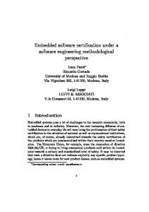
Automated program synthesis aims at automatically constructing executable programs from high-level specifications. It is usually based on mathematical logic, although a variety of different approaches exist4. Here, we will focus on a specific approach, schema-based program synthesis, and a specific system, AUTOBAYES. Externally, AUTOBAYES looks like a compiler: it takes an abstract problem specification and translates it into executable code. Internally, however, it is quite different. AUTOBAYES5 generates complex data analysis programs from compact specifications in the form of statistical models. It has been applied to a number of domains, including clustering, change detection, sensor modeling, and software reliability modeling, and has been used to generate programs with up to 1500 lines of C++ code. First, AUTOBAYES derives a customized algorithm implementing the model and then it produces an optimized, imperative code implementing the algorithm. The following figure shows the system architecture:
Const nat n. Const nat c = 3 … Data double x(I:=1..n) – gauss{mu(c(I)).sigma(c(I))). Max pr(x | (phi, mu, sigma) for (phi, mu sigma).
Model specification
TEST DATA GENERATOR
SYNTHESIS KERNEL
Schema Library Intermediate code
OPTIMIZER Intermediate code
CODE CODEGENERATOR GENERATOR 3.232323 3.342387 5.125683 3.891308 3.550812 5.412456 3.000217 2.994381 3.244621 Raw Data
For i=0;i=n;i++ { For j=0;j