Progress towards developing the TMT adaptive optical systems and their components Brent Ellerbroek1a, Sean Adkinsb, David Andersenc, Jenny Atwoodc, Corinne Boyera, Peter Byrnesc, Rodolphe Conand, Luc Gilles a, Glen Herriotc, Paul Hicksone, Ed Hilemanf, Dick Joycef, Brian Leckiec, Ming Liangf, Thomas Pfrommere, Jean-Christophe Sinquing, Jean-Pierre Veranc, Lianqi Wang a, and Paul Wellec a
TMT Observatory Corporation, 2632 E. Washington Blvd, Pasadena, CA USA 91107; b W. M. Keck Observatory, 65-1120 Mamalahoa Highway, Kamuela, HI USA 96743; c Herzberg Institute of Astrophysics, 5071 W. Saanich Road, Victoria, BC Canada V9E 2E7; d University of Victoria, PO Box 3055 STN CSC, Victoria, BC Canada V8W 3P6; e University of British Columbia, 6224 Agricultural Road, Vancouver, BC Canada V6T 1Z1; f National Optical Astronomy Observatories, 950 N. Cherry Ave, Tucson, AZ USA 85719; g CILAS, 8 Avenue Buffon - ZI La Source, Orleans, France 45100 ABSTRACT Atmospheric turbulence compensation via adaptive optics (AO) will be essential for achieving most objectives of the TMT science case. The performance requirements for the initial implementation of the observatory’s facility AO system include diffraction-limited performance in the near IR with 50 per cent sky coverage at the galactic pole. This capability will be achieved via an order 60x60 multi-conjugate AO system (NFIRAOS) with two deformable mirrors optically conjugate to ranges of 0 and 12 km, six high-order wavefront sensors observing laser guide stars in the mesospheric sodium layer, and up to three low-order, IR, natural guide star wavefront sensors located within each client instrument. The associated laser guide star facility (LGSF) will consist of 3 50W class, solid state, sum frequency lasers, conventional beam transport optics, and a launch telescope located behind the TMT secondary mirror. In this paper, we report on the progress made in designing, modeling, and validating these systems and their components over the last two years. This includes work on the overall layout and detailed opto-mechanical designs of NFIRAOS and the LGSF; reliable wavefront sensing methods for use with elongated and time-varying sodium laser guide stars; developing and validating a robust tip/tilt control architecture and its components; computationally efficient algorithms for very high order wavefront control; detailed AO system modeling and performance optimization incorporating all of these effects; and a range of supporting lab/field tests and component prototyping activities at TMT partners. Further details may be found in the additional papers on each of the above topics. Keywords: Extremely Large Telescopes, Adaptive Optics
1. INTRODUCTION The TMT Project1 is proceeding with its Design and Development Phase (DDP), towards the long-term goal of constructing and operating a 30-meter-diameter optical/infra-red telescope for research in astronomy. Important milestones over the last two years have included the completion of the site selection measurement campaign2, formalization of the observatory’s overall requirements3 and design architecture4, and the development of a detailed cost estimate and a technically-driven schedule for the Construction Phase5. The development of subsystem-level requirements, designs, and performance estimates is progressing across the project, as described in the related papers presented at this symposium6-10. Adaptive optics (AO) remains an essential ingredient for many if not most of the TMT science cases11. The fundamental requirements and top-level design architecture for the early light TMT AO systems have also remained essentially the 1
[email protected]; phone 1 626 395 1620; fax 1 626 395-1615; www.tmt.org Adaptive Optics Systems, edited by Norbert Hubin, Claire E. Max, Peter L. Wizinowich, Proc. of SPIE Vol. 7015, 70150R, (2008) 0277-786X/08/$18 · doi: 10.1117/12.788057 Proc. of SPIE Vol. 7015 70150R-1 Downloaded from SPIE Digital Library on 19 Sep 2011 to 137.82.117.28. Terms of Use: http://spiedl.org/terms
same over the last two years. However, considerable progress has occurred in evaluating the optimizing the expected performance of these systems, developing designs for their opto-mechanical hardware and control systems, and advancing the state-of-the-art for the required AO component technology. Each of these topics is described further in the following pages and related papers12-15,17-21,25-26,31.
2. REQUIREMENTS AND DESIGN CHOICES 2.1 Top-level and derived requirements The detailed top-level requirements for the TMT early light adaptive optics are described in Sections 3.3.15 and 3.3.18 of our Observatory Requirements Document (ORD)3. These requirements have been defined to provide diffractionlimited atmospheric turbulence compensation for the near infra-red (IR) instruments IRIS, IRMS, and NIRES. In general terms, these requirements include: •
High throughput in the J, H, and K, and (as a strong goal) I spectral bands with very low thermal emission;
•
Diffraction-limited near IR image quality over a “narrow” field-of-view of 10-30 arc seconds, which is still significantly larger than the isoplanatic patch size;
•
50% sky coverage at the galactic pole;
•
Excellent photometric and astrometric accuracy; and finally
•
High observing efficiency, with a minimum of downtime and night-time calibration.
These general considerations already define most of the basic features of the early light adaptive optics for TMT. High sky coverage can only be achieved using laser guide star (LGS) AO for higher-order wavefront correction. Furthermore, the requirement for diffraction-limited wavefront compensation and the large TMT aperture diameter imply a need for multiple LGS and tomographic wavefront reconstruction to defeat the cone effect, which would result in an unacceptably large wavefront error with only a single LGS. Additionally, the diameter of the science field and the requirements on photometric and astrometric accuracy imply the use of multi-conjugate AO (MCAO), which provides atmospheric turbulence compensation over an extended field by using multiple deformable mirrors (DMs) conjugate to several different ranges in the atmosphere. Next, the TMT aperture diameter and the specifications for diffraction-limited image quality combine to yield requirements for very high order wavefront sensing and correction, as well as very high control bandwidths. These requirements in turn imply a need for bright laser guide stars and computationally efficient wavefront control. Schedule risk should be minimized to be ready for first light, so all of these devices must be based upon existing or near-term AO component technology wherever possible. The demanding specifications for sky coverage also place important requirements upon the approach to natural guide star (NGS) tip/tilt wavefront sensing. IR tip/tilt sensing will be necessary, both because of the higher density of “red” (K and M class) guide stars and the fact that “sharpening” (AO compensation) of the IR images permits the use of dimmer guide stars. Even so, a large tip/tilt WFS patrol field will still be needed to maximize the probability of detecting a sufficiently bright guide star. Because the tip/tilt measurements obtained from a single off-axis NGS are corrupted by tilt anisoplanatism, multiple tip/tilt guide stars must be utilized to estimate tip/tilt in the direction of the science object via a process of interpolation. Finally, the specification to minimize thermal emission requires a cooled AO optical path. 2.2 Design description Conforming with the above requirements, the early light TMT adaptive optics are based upon a LGS MCAO architecture consisting of three major systems: (i) the facility Narrow Field IR AO System (NFIRAOS), which is located on the TMT nasmyth platform and relays light from the telescope to three science instrument ports after sensing and correcting for wavefront aberrations introduced by atmospheric turbulence and the observatory itself; (ii) the Laser Guide Star Facility (LGSF), which generates multiple LGS in the mesospheric sodium layer with the brightness, beam quality, and asterism geometry required by the NFIRAOS wavefront sensors (WFSs); and (iii) the Adaptive Optics Sequencer (AOSQ), which automatically coordinates the operations of NFIRAOS and the LGSF with the remainder of the observatory for safe and
Proc. of SPIE Vol. 7015 70150R-2 Downloaded from SPIE Digital Library on 19 Sep 2011 to 137.82.117.28. Terms of Use: http://spiedl.org/terms
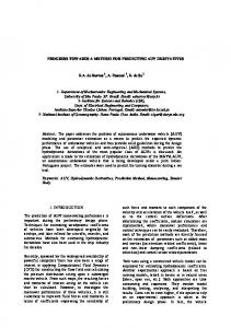
efficient observations. The locations of NFIRAOS and the LGSF are illustrated in Figure 1 below. In the remainder of this subsection, we will describe the “design” of these AO systems in terms of the decisions made regarding key component technologies, high-level design options, and the values of the fundamental AO parameters (e.g. control bandwidth) that determine the performance of the AO control loop. Laser Lauch Telescope and diagnostics
LGSF Beam Transfer Optics
NFIRAOS and client instruments
Laser Service Enclosure (LSE)
Table 1: Technologies Selected for Critical AO Components. Component
Technology
Sodium guide star lasers
Solid state, continuous wave (CW), sum frequency
Laser beam transport
Conventional optics (not fibers)
Deformable mirrors
Piezostack actuator
Low order, IR NGS WFS detectors
Intensified CCD array
LGS WFS detectors
“Polar coordinate” CCD array
Real time (RTC)
DSP and FPGA hardware and efficient algorithms
controller
Figure 1: Early light TMT AO systems
Table 1 summarizes the choices made regarding critical component technologies for the early light adaptive optics. The options selected for the lasers, beam transport, deformable mirrors, and low-order NGS WFS detectors represent relatively modest extrapolations to existing devices, which may be incorporated into practical designs with minimal risk and acceptable cost. However, the more ambitious approach chosen for the real time controller (RTC) is mandated by the sheer size of the wavefront control problem for TMT (section 5). We have also selected the “polar coordinate” CCD array concept (now under development by the Adaptive Optics Development Program) for LGS WFS to reduce the impact of laser guide star elongation (sections 5.2 and 6.2).
Table 2: High-Level Design Choices Design Choice
Decision
Laser launch location
Behind TMT secondary mirror
Laser location
Within telescope azimuth structure
Low-order NGS WFS location
Within NFIRAOS instruments
Field de-rotation
Bearing at NFIRAOS-to-instrument interface
Tip/tilt control architecture
“Woofer-tweeter” control, with a DM mounted on a tip/tilt platform
client
Table 2 summarizes some of the high-level design choices selected for the NFIRAOS and LGSF designs. Laser beams will be projected from behind the TMT secondary mirror to minimize the magnitude of LGS elongation, which would be approximately twice as large if the beams were launched from the edge of the TMT primary mirror. The laser service enclosure (LSE) is located within the telescope azimuth structure; this permits the lasers to operate with a fixed gravity vector, but requires a longer and more sophisticated beam path to transmit the laser light onto the telescope center section and thence to the launch telescope. Turning to the design of NFIRAOS, we have decided to transfer the requirements for field de-rotation and low order NGS wavefront sensing onto the NFIRAOS science instruments, since this will help to reduce the number of “warm” optical surfaces within the AO system, and also minimize the un-sensed tip/tilt/focus biases between the low-order wavefront sensors and the scientific focal plane. Additionally, one of the NFIRAOS deformable mirrors will be mounted on a tip/tilt platform to eliminate the need for a separate tip/tilt mirror and further reduce the number of optical surfaces. A form of “woofer-tweeter” control32 will be implemented, with the high frequency, low-amplitude tip/tilt errors corrected by the DM figure actuators instead of the tip/tilt stage. Finally, Table 3 lists the first-order AO component requirements for NFIRAOS and the LGSF that will determine the potential performance of the control loop. Derived and validated using detailed modeling codes, these design parameters yield a delivered, on-axis RMS wavefront error of about 187 nm (including implementation error sources and a design
Proc. of SPIE Vol. 7015 70150R-3 Downloaded from SPIE Digital Library on 19 Sep 2011 to 137.82.117.28. Terms of Use: http://spiedl.org/terms
margin of about 70 nm RMS) for the early light TMT AO system. Further details of the error budget are presented in Section 3 below.
3. PERFORMANCE ANALYSIS SUMMARY The quantified image quality requirement for the TMT early light adaptive optics is a delivered on-axis RMS wavefront error (WFE) of 187 nm, which is allowed to degrade to values of 191 and 208 nm RMS for extended fields-of-view with diameters of 10 and 30 arc seconds, respectively. These requirements include both tip/tilt and higher-order wavefront aberrations due to both fundamental AO error sources and implementation error terms. Table 4 is a summary of our current error budget, which meets the on-axis requirement with a contingency (in quadrature) of 72 nm RMS. The tip/tilt-removed terms in Table 4 are based upon detailed analysis and simulation of the NFIRAOS and LGSF systems. Beyond the usual elements of a basic AO simulation, some of the features which have been modeled include: physical optics and guide star elongation effects in the LGS WFS, the actual LGS WFS pixel processing and wavefront reconstruction algorithms specified for the NFIRAOS RTC, the TMT telescope pupil function with current estimates for static and dynamic optical errors, the variability of the mesospheric sodium layer, and DM hysteresis. Please see the companion paper on TMT AO simulations for further details12.
Table 3: First-order AO component requirements Requirement
Value
Laser power per guide star, W
25
LGSF optical throughput
0.75
Launch telescope aperture, m
0.5
LGSF delivered Strehl
0.80, high spatial frequency errors 0.70, low spatial frequency errors
Order of wavefront compensation
60x60
Control loop update rate, Hz
800
DM conjugate ranges, km
0 and 12
LGS asterism
1 on-axis guidestar and 5 guide stars at a 35 arc sec radius
LGS WFS pixel size and read noise
0.5 arc seconds and 5 electrons
Tip/tilt NGS WFS pixel size, read noise, and quantum efficiency
4 milli arc sec, < 1 electron, 0.3
Table 4: Summary AO error budget Error term Total error Tip/tilt-removed error
On-axis RMS WFE, nm 187 161
First-order turbulence compensation
120
Implementation errors
108
Opto-mechanical
84
AO component and higher-order effects
68
Tip/tilt error
61
The tip/tilt error listed on the final line of Table 4 is Contingency 72 an estimate of the performance achieved with 50 per cent sky coverage at the galactic pole. This estimate has improved considerably over the past two years, primarily on account of changes and improvements to the assumed guidestar model, the TMT windshake disturbance model, and the “woofer/tweeter” servo transfer function used to implement the tip/tilt control. Some additional improvement is also expected to be obtained through the use of a commercially available, intensified CCD array (the Intevac MOSIR 950) with essentially zero detector read noise and a quantum efficiency of about 0.3 in the J+H wavefront sensing bands. Since the low order NGS wavefront sensors must operate with faint guidestars, the reduced QE of this device is more than compensated by the very low detector read noise and dark current. Of course, this level of tip/tilt jitter compensation still depends strongly upon (i) the “sharpening” of the guide star images provided by the AO system, and (ii) the detection and correction of tilt anisoplanatism using multiple NGS wavefront sensors and MCAO. Further details on the tip/tilt control architecture are provided in an additional paper13. Further AO simulations and performance modeling are planned for the remaining year of the TMT Design Development Phase. Some of the topics to be investigated include: AO performance variability over a range of zenith angles and seasonal turbulence profiles, further modeling of implementation error sources as the designs for the telescope and client instruments mature, and enhanced-fidelity Monte Carlo sky coverage simulations based upon integrated, physical optics modeling of both the higher-order (LGS) and tip/tilt (NGS) control loops. We will also develop performance estimates for the order 120x120 “NFIRAOS+” AO system upgrade, and construct error budgets for high precision astrometry and photometry including all significant AO, instrument, and observatory error terms.
Proc. of SPIE Vol. 7015 70150R-4 Downloaded from SPIE Digital Library on 19 Sep 2011 to 137.82.117.28. Terms of Use: http://spiedl.org/terms
4. OPTO-MECHANICAL DESIGN DEVELOPMENT 4.1 Narrow Field Infra-Red AO System (NFIRAOS) The essential optical form of the 2 Truth NGS WFSs IR acquisition NFIRAOS optical design has remained 1 60x60 NGS WFS camera unchanged. It consists of an off-axis parabola (OAP) relay, which creates a Input from telescope collimated optical path containing a pair of deformable mirrors optically conjugate to ranges of 0 and 12 km in OAP the atmosphere above the telescope. OAP The implementation of this concept has 75x75 DM at h=12 km 63x63 DM at h=0 km on tip/tilt platform evolved considerably since the time of Output to science the NFIRAOS conceptual design review instruments and IR IR in mid-2006, however. The LGS and T/T/F WFSs Visible NGS optical paths have been Laser repackaged to relocate NFIRAOS to the 6 60x60 LGS WFSs opposite Nasmyth platform, and to reduce wind cross section. As well the LGS optics have been completely redesigned to move them out of the cold enclosure, simplify the prescriptions of Figure 2: NFIRAOS bench opto-mechanical layout the large refractive elements in the design, and simply the implementation of the “zoom” focus adjustments used to track the variable range to the sodium layer. The NGS optical path now includes a pair of moderate- and high order “truth” wavefront sensors, which are used to detect the biases in the LGS WFS measurements arising from uncertainties in the shape of the sodium layer profile. The output science path now includes an additional port for an IR acquisition camera, in addition to the three client instruments previously planned. Work on the thermal control system is also progressing, as well as the opto-mechanical interfaces to the TMT nasmyth platform and the three client instruments. Figure 3 illustrates the mechanical interface with the nasmyth platform and the relative locations of the NFIRAOS bench, electronics enclosure, and client instruments. Please see the associated papers14-15 for further details.
Future (third) Instrument NFIRAOS Service Platform
BTO Path
4.2 Laser Guide Star Facility (LGSF) As illustrated in Figure 1 above, the principal change to the overall layout of the LGSF has been to move the laser service enclosure (LSE) to a new location within the telescope azimuth structure. The dimensions of the new LSE (approximately 12x4.5x3 m) have been sized to house three copies of the current Gemini-South 50W laser system16, the associated electronics, an air handling unit to maintain a class 10,000 clean room environment, and an ancillary gown room. A rail crane located above the LSE will be used to install and position the lasers and their electronics within the room.
Bench and Instrument Support LGS WFS
IRIS
Nasmyth Platform Interface Electronics Enclosure
Nasmyth Platform
Although the new LSE location will provide a fixed Figure 3: NFIRAOS enclosure, illustrating the interfaces to the TMT nasmyth platform and client instruments gravity vector orientation and simplify the laser system design, the beam transfer optics (BTO) path has been lengthened and must now transfer the beams onto the rotating telescope elevation structure. As illustrated in Figure 3, this transfer occurs along the telescope elevation axis in close proximity to NFIRAOS, and directly in front of the
Proc. of SPIE Vol. 7015 70150R-5 Downloaded from SPIE Digital Library on 19 Sep 2011 to 137.82.117.28. Terms of Use: http://spiedl.org/terms
—
planned location of the Alignment and Phasing System (APS) and the future Planet Formation Instrument (PFI). This segment of the beam duct must consequently retract for operation and maintenance of these two instruments.
LLT & LLT Bench
ULAO Upgrade
Fcr Field Cce,ere
I
The controls architecture of the BTO has also been updated for the new beam path, as illustrated in Figure 4. The output of each 50W laser is split into 2-3 beams at the LSE, and the resulting 3-8 beams (6 for NFIRAOS; a variable number for future LGS AO systems) propagate along static paths until reaching the telescope elevation axis. At that point, a pair of active mirror arrays is used to track the rotation of the telescope elevation structure, and then align the beams onto the remainder of the optical path. The rest of the route to the launch telescope is functionally equivalent to the original LGSF design, although the optical design of the relay lenses will need to be modified to account for increased total length of the path.
Asterism Generator
Diagnostic System
TrssCsrtsrrg
Ay (TCA)
(TRIF
TbPodFoldf'
P00cc
I[L
E
FapSteeeeg _________
\ ______
offooo42Oeoo, El73300e,, oo:-l
BTOOpt,calPath
(TOEL)
I
Deployable Optical Path Deployable
Deployable
%Po00oy\T0ae0 Laser Service — —
—y
Truss Fold ________________________ Array(TFA)
I
Enclosure Safety
Deployable Fold -
I
oy:D:5OOH
End
Elevation Optical Path
Array (DFA)
L 1
Azimuth Optical Path LSE Fold Array (LSEFA)
L
Figure 4: Beam Transfer Optics (BTO) Schematic
Finally, the top-end components of the LGSF have been reconfigured for compatibility with the TMT top end re-design, which was recently implemented for the telescope’s new Ritchey-Chrétien optical prescription. The new layout of the topend components, including the diagnostics bench, asterism generator, launch telescope, and electronics enclosures, is illustrated in Figure 5. The number of optical elements in the high power beam paths has been reduced, and pointing of the launch telescope is now adjustable in one dimension to compensate for flexure of the telescope top end. The mass, moments, and cross section of this conceptual design have been computed, and are consistent with their requirements. Further details on the updated LGSF layout and design may be found in a separate paper on this subject17.
Electronics Enclosures
Launch Telescope
Truss Centering Array
Diagnostics Bench Asterism Generator
Figure 5: Conceptual Design of the LGSF Top End
5. CONTROL ARCHITECTURE DEVELOPMENT 5.1 Real time controller (RTC) architecture The NFIRAOS RTC is one of the most challenging AO subsystems for TMT. Some of its requirements include very high order LGS WFS pixel processing with highly elongated laser guide stars, low-order NGS WFS pixel processing, very high-order tomographic wavefront reconstruction using measurements from these multiple sensors, real-time optimization of the algorithms used for all of these processes, turbulence parameter estimation, and DM and WFS data acquisition to reconstruct (or estimate) the AO-compensated PSF in post-processing. The RTC must interface with all of the wavefront sensing- and correcting components located within NFIRAOS, with I/O and computation rates which are at least one to two orders of magnitude more demanding than any astronomical AO system in operation today. New AO control algorithms and hardware implementations will be necessary to meet these requirements.
Proc. of SPIE Vol. 7015 70150R-6 Downloaded from SPIE Digital Library on 19 Sep 2011 to 137.82.117.28. Terms of Use: http://spiedl.org/terms
RTC Block Diagram - LGS AD operation mode Figure 6 is a top-level block To/From To/From To/From RPG To/From RPG LGSF diagram of the updated RTC LGS masked RPG A scb-aportcros & A FSM A control architecture for the DMSD& FSM a & mtt r& temporal filter gem strengths of tcrboleece multi-conjugate LGS AO & LGS fade [radootaIoorim mode. Some aspects of this architecture which have From LGS grttetts received considerable attention over the past year include the From TCS implementation of temporal filters and telescope offloads in the wavefront corrector control processes; the LGS and NGS WFS “matched filter” gradient estimation algorithms, which are adaptively updated in real time as atmospheric conditions UF change; real-time estimation of the turbulence profile and atmospheric parameters; and Rotator angte & the “split tomography” Gradient modes PSDs & El Rotator angto offset & noise Temporal filter gains ante conarianoe TTFWFSpr0b0 wavefront reconstruction matnO position offsets To To/From NFIRAOS algorithm, which decomposes RPG CC From TCS To RPG From/To Instrament the atmospheric turbulence profile into two orthogonal Figure 6: Top-level RTC control block diagram for the LGS AO mode subspaces which are estimated and controlled separately using the NGS and LGS WFS measurements. The principal advantages of this last approach include (i) simplified real-time optimization of the NGS control problem as the guide star asterism and atmospheric turbulence conditions change, and (ii) a simplified formulation for the LGS atmospheric tomography problem, which evidently permits simpler algorithms to be implemented which would otherwise degrade the correction of the NGScontrolled subspace.
rs
eing
I
LTse=er
I
Two of the most critical aspects of the RTC control architecture are described further in the following subsections and several related papers18-21. 5.2 Laser guide star wavefront sensing AO systems utilizing sodium laser guide stars must contend with the elongation effects induced by the depth of the sodium layer, at least for the current generation of continuous wave (CW) and quasi CW laser systems. The magnitude of guidestar elongation for TMT will be greater than for any existing LGS AO system, and the impact upon performance could be significant if current LGS WFS designs and processing algorithms were employed22. TMT will implement a variety of design improvements to mitigate these elongation effects19. First, the laser launch telescope will be located behind the TMT secondary mirror, which reduces the magnitude of the (worst-case) LGS elongation by at least a factor of two in comparison with off-axis laser propagation. Secondly, the TMT LGS wavefront sensors will make use of the so-called “polar coordinate” CCD array pixel geometry now being prototyped under an AODP grant23. With this array, each of the 60x60 subaperture images of the LGS will be imaged onto a separate island of from 6x6 to 6x15 pixels aligned along the direction of LGS elongation. This concept significantly reduces the total number of pixels in the CCD array, thereby permitting a combination of reduced signal processing requirements, reduced pixel read rates, lower detector read noise, and improved spatial sampling of the LGS image. LGS elongation will still increase the wavefront sensing errors due to noise, and TMT will require considerably more laser power per guide star than current LGS AO systems on 8-10m class telescopes for equivalent performance. However, the increase in laser requirements can be minimized if a noise-optimal matched filter algorithm24 is used for estimating the subaperture wavefront gradients from the Shack-Hartmann spots. As illustrated in Figure 7, the RMS wavefront error due to noise can be reduced (for one sample sodium layer profile and a representative LGS signal level) by roughly a factor of 1.6 in comparison with the standard centroid algorithm. Laser power requirements are consequently reduced by about a factor of two for TMT’s expected “blend” of detector read noise and photon shot noise.
Proc. of SPIE Vol. 7015 70150R-7 Downloaded from SPIE Digital Library on 19 Sep 2011 to 137.82.117.28. Terms of Use: http://spiedl.org/terms
Additionally, the linear dynamic range of the matched filter algorithm can be significantly improved through the inclusion of appropriate constraint equations (Figure 8). Given this refinement, the residual wavefront errors due to WFS nonlinearities are predicted to be smaller for the constrained matched filter than for the standard centroid approach.
Edge Subaperture
Incremental Tip/Tilt Removed WFE
100
120
Constrained Filter 100
It) CO
Cdntroid
0
I
F5°
40 20
200 400 600 800 Simulation Time Step Figure 7: Incremental RMS wavefront error due to noise for the constrained matched filter and standard centroid algorithm
-100 -500
-250
0
250
500
Input Tilt (mas) Figure 8: Matched filter nonlinearity for a WFS subaperture at the edge of the TMT pupil, with and without linearity constraints
As the name implies, the matched filter algorithm must be correctly “matched” to the shape of the sodium layer profile to obtain these performance advantages. NFIRAOS will utilize a combination of several sensing strategies and background processing tasks to measure the changes in the sodium layer profile and appropriately adjust the matched filter coefficients in real time19. The matched filter offsets will be updated at a rate of ~0.1 Hz based upon wavefront measurements from a NGS “Truth” WFS (TWFS), following an approach similar to that already implemented at Keck Observatory22,25. The matched filter gains will be updated at a similar rate, based upon the derivatives of the LGS WFS pixel intensities with respect to wavefront tip and tilt. These derivatives will in turn be estimated by “dithering” the guide star pointing on the sky20. The University of Victoria LGS WFS testbed21 has now experimentally validated the linearity and reduced sensitivity to noise of the matched filter algorithm, and has also demonstrated that the algorithm can be successfully updated in real time to track the variations in the sodium layer. However, additional sodium layer measurements with higher temporal resolution are needed to accurately predict the performance that will actually be achieved using these algorithms in the field. Such LIDAR campaigns are planned during the remainder of this year at Arecibo (1-10 Hz measurements) and with new University of British Columbia LIDAR system (10-100 Hz)26. 5.3 Computationally efficient wavefront reconstruction The NFIRAOS wavefront reconstruction problem requires the computation of over 7000 DM actuator commands from about 35000 LGS WFS measurements at a frame rate of 800 Hz. The standard matrix-vector-multiply (MVM) solution becomes very impractical for systems of this dimensionality, particularly if the control matrix must be updated in real time to account for changes in the atmospheric turbulence profile, rotation of the TMT pupil, or other time-varying effects. Computationally efficient algorithms must be implemented instead18. Generally speaking, these algorithms implement close approximations to minimum variance atmospheric tomography (i.e., estimating the atmospheric turbulence profile from the LGS WFS measurements) and least-squares DM fitting (fitting DM actuator commands to the estimated turbulence profile). Some of the candidate approaches include (i) iterative algorithms such as conjugate gradients (CG), possibly employing a preconditioner in either the spatial or Fourier domain, or (ii) Block-Gauss-Seidel solutions to block structured representations of the tomography problem. Each approach can be expressed as a combination of lower-level processes including sparse matrix operations, geometrical wavefront propagation through square grids, Fourier transforms, and/or Cholesky back-substitution through triangular sparse matrices.
Proc. of SPIE Vol. 7015 70150R-8 Downloaded from SPIE Digital Library on 19 Sep 2011 to 137.82.117.28. Terms of Use: http://spiedl.org/terms
Four promising algorithms have now been identified out of a wider initial range of candidates. These four options yield equivalent and essentially optimal performance in detailed AO simulations, with their time-averaged RMS wavefront errors varying by no more than 15 nm RMS in quadrature. Their computation and memory requirements have been estimated and appear to be feasible in relation to the performance specifications of current DSP and FPGA processors. The implementation of several of these algorithms will be addressed in a pair of upcoming RTC conceptual design studies, after which a final choice of algorithm will be made.
6. AO COMPONENT DEVELOPMENT 6.1 Wavefront correctors The wavefront correcting components in NFIRAOS include a pair of 63x63 and 75x75 piezostack deformable mirrors with 5mm interactuator pitch, and a 20 Hz tip/tilt platform (TTP) which serves as the mount for the first of these deformable mirrors. The top-level requirements for the DMs (which must be satisfied at the NFIRAOS operating temperature of -30C) include 8-10 µm actuator stroke, 5% hysteresis, and a mirror figure error after flattening of 20 nm RMS. As presented previously27, all of these requirements have been demonstrated by the subscale 9x9 prototype DM which was fabricated and tested by CILAS in 2006. More recently, a 41x41 CILAS DM has been successfully demonstrated for the ESO SPHERE AO system using the same materials and components in a very similar design28. CILAS is now developing a prototype TTP for TMT. NFIRAOS will utilize this TTP instead of a separate tip/tilt mirror to maximize the optical throughput of the system, and minimize the size and complexity of the opto-mechanical design. Although smaller deformable mirrors have been successfully mounted on tip/tilt platforms in other AO systems29, the requirements for Figure 9: Cross section of CILAS tip/tilt platform prototype design NFIRAOS are exceptional in terms of the mass and size of the DM. The bandwidth requirement for the TTP is therefore limited to 20 Hz, and the remaining high-frequency, low-amplitude component of the tip/tilt disturbances will be corrected by the DM piezostack actuators using “woofertweeter” control13. The prototyping effort at CILAS has now reached the fabrication and assembly phase. Testing is expected to begin in late summer, with final demonstrations and acceptance testing by the end of calendar year 2008. 6.2 LGS wavefront sensing detectors A one-quadrant prototype of the LGS WFS polar coordinate CCD will be fabricated and tested under a grant from the NSF Adaptive Optics Development Program23. The design of the prototype has been completed, the etch masks have been produced, and the prototype arrays themselves are expected to be fabricated in a foundry run later this year. The low-noise vertical JFET amplifier used in the design has already been successfully demonstrated in a more conventional CCD array with 160x160 pixels. Sub-electron read noise was achieved, although ~3 electrons of read noise are expected for the faster pixel read rates required for the polar coordinate CCD. 6.3 Guide star lasers Given the current state of the technology, TMT continues to assume either a continuous wave (CW) or a quasi-CW laser with an acceptable pulse format as the baseline for the laser guide star facility. The NFIRAOS error budget in section 3 above is based upon 25W of laser power per guide star (at the output of the laser), a sodium column density of 4x10¹³, a round-trip optical/atmospheric transmittance of 0.19, and a sodium layer coupling efficiency of 130 photons-
Proc. of SPIE Vol. 7015 70150R-9 Downloaded from SPIE Digital Library on 19 Sep 2011 to 137.82.117.28. Terms of Use: http://spiedl.org/terms
m2/W/s/ion/SR. 150W of total laser power is required to generate the NFIRAOS asterism of 6 guide stars, and the Laser Service Enclosure (LSE) has been sized to accommodate the mass and volume of 3 50W-class lasers based upon the characteristics of the two current designs which have already demonstrated this power level16,30. Although the LGS signal level is likely to vary considerably based upon seasonal variations in the sodium column density, atmospheric transmittance, and (possibly) shortfalls in LGSF performance, a factor of 2 to 4 reduction in LGS brightness increases the total residual wavefront error (in quadrature) by about 43 to 75 nm RMS.
ACKNOWLEDGEMENTS The authors gratefully acknowledge the support of the TMT partner institutions. They are the Association of Canadian Universities for Research in Astronomy (ACURA), the California Institute of Technology and the University of California. This work was supported as well by the Gordon and Betty Moore Foundation, the Canada Foundation for Innovation, the Ontario Ministry of Research and Innovation, the National Research Council of Canada, the Natural Sciences and Engineering Research Council of Canada, the British Columbia Knowledge Development Fund, the Association of Universities for Research in Astronomy (AURA) and the U.S. National Science Foundation.
REFERENCES [1] [2]
[3] [4] [5] [6] [7] [8] [9] [10]
[11] [12] [13] [14] [15] [16]
[17] [18]
G. Sanders and J. Nelson, “The status of the Thirty Meter Telescope project”, Proc. SPIE 7012 (2008). M. Schöck, S. G. Els, R. L. Riddle, W. Skidmore, T. Travouillon, R. D. Blum, E. Bustos, P. Gillett, B. Gregory, J. E. Nelson, J. Seguel, J. Vasquez, K. Vogiatzis, D. Walker, and Lianqi Wang, “Status of the Thirty Meter Telescope site selection program”, Proc. SPIE 7012 (2008). TMT Observatory Requirements Document, http://www.tmt.org/foundation-docs/ORD-CCR18.pdf (2008). TMT Observatory Architecture Document, http://www.tmt.org/foundation-docs/OAD-CCR17.pdf (2008). TMT Construction Proposal, http://www.tmt.org/news/TMT-Construction%20Proposal-Public.pdf (2007). D. Crampton, L. Simard, D. Silva, “Early Light TMT instrumentation”, Proc. SPIE 7014 (2008). G. Z. Angeli and S. Roberts, “Systems engineering for the preliminary design of the Thirty Meter Telescope”, Proc. SPIE 7017 (2008). K. Szeto, S. Roberts, M. H. Gedig, C. Lagally, D. Tsang, D. G. MacMynowski, M. J. Sirota, L. M. Stepp, P. M. Thompson, “TMT telescope structure system: design and development progress report”, Proc. SPIE 7012 (2008). E. C. Williams, T. S. Mast, J. E. Nelson, E. R. Ponslet, V. Stephens, and L. M. Stepp, “Primary mirror segmentation studies for the Thirty Meter Telescope”, Proc. SPIE 7018 (2008). E. C. Williams, C. Baffes, T. S. Mast, J. E. Nelson, B. Platt, A. Ponchoine, E. R. Ponslet, S. Setoodeh, M. J. Sirota, V. Stephens, L. M. Stepp, and A. Tubb, “Advancement of the segment support system for the Thirty Meter Telescope primary mirror”, Proc. SPIE 7018 (2008). TMT Detailed Science Case, http://www.tmt.org/foundation-docs/TMT-DSC-2007-R1.pdf (2007) Lianqi Wang, Luc Gilles, and Brent Ellerbroek, “Modeling Update for the Thirty Meter Telescope Laser Guide Star Dual-Conjugate Adaptive Optics System”, Proc. SPIE 7015 (2008). Lianqi Wang, Brent Ellerbroek, Jeam-Pierre Veran and Jean-Christophe Sinquin, “The NFIRAOS tip/tilt control architecture and sky coverage for TMT”, Proc. SPIE 7015 (2008). G. Herriot, D. Andersen, J. Atwood, C. Boyer, P. Byrnes, B. Ellerbroek, L. Gilles, P. Hickson, B. Leckie, J.P. Veran, L. Wang, and P. Welle, “NFIRAOS – TMT’s initial adaptive optics system”, Proc. SPIE 7015 (2008) J. Atwood, P. Byrnes, P. Welle, and G. Herriot, “Present Optical and Mechanical Design Status of NFIRAOS for TMT”, Proc. SPIE 7015 (2008). I. Lee, G. Moule, M. P. Jalali, N. Vanasse, K. W. Groff, N. Rogers, A. K. Hankla, J. Roush, C. d'Orgeville, S. M. Adkins, and Z. Prezkuta, “20 W and 50 W guidestar laser systems update for the Keck I and Gemini South telescopes”, Proc. SPIE 7015 (2008). Corinne Boyer, Brent Ellerbroek, Mike Gedig, Edward Hileman, Richard Joyce, and Ming Liang, “Update on the TMT laser guide star facility design”, Proc. SPIE 7015 (2008). C. Boyer, L. Gilles, B. Ellerbroek, G. Herriot, and J.P. Veran, “Update on the TMT adaptive optics real time controller”, Proc. SPIE 7015 (2008).
Proc. of SPIE Vol. 7015 70150R-10 Downloaded from SPIE Digital Library on 19 Sep 2011 to 137.82.117.28. Terms of Use: http://spiedl.org/terms
[19]
[20] [21] [22] [23] [24] [25] [26] [27]
[28] [29]
[30]
[31] [32]
Glen Herriot, Rod Conan, Olivier Lardière, David Andersen, Brent Ellerbroek, Luc Gilles, Paul Hickson, Kate Jackson, Jean-Pierre Véran, Lianqi Wang, “Compensation of TMT laser wavefront sensors for variations of sodium layer”, Proc. SPIE 7015 (2008). R. Conan, O. Lardiere, K. Jackson, G. Herriot and C. Bradley, “Modeling of the Thirty-Meter-Telescope matchedfilter-based wavefront sensing”, Proc. SPIE 7015 (2008). R. Conan, O. Lardiere, K. Jackson, G. Herriot and C. Bradley, “Sodium LGS wavefront sensing test bench for the Thirty-Meter-Telescope”, Proc. SPIE 7015 (2008). R. M. Clare, M. A. van Dam, and A. H. Bouchez, “Modeling low order aberrations in laser guide star adaptive optics systems”, Optics Express 15, 4711-4725 (2007). J. W. Beletic, "Follow the yellow-orange rabbit: a CCD optimized for wavefront sensing a pulsed sodium laser guide star," Proc. SPIE 5499, 302-309 (2004). L.Gilles and B.L.Ellerbroek, “Constrained Matched Filtering for Extended Dynamic Range and Improved Noise Rejection For Shack-Hartmann Wavefront Sensing”, Opt. Lett. 33 (2008). D.Andersen, B.Ellerbroek, J.-P.V´eran and L.Wang, “Negating effects from sodium profile variations for TMT: the MOR truth wavefront sensor for NFIRAOS”, Proc. SPIE 7015 (2008). T. Pfrommer, P. Hickson, C.-Y. She and J. Vance, “Lidar experiment for high spatio-temporal resolution of the mesospheric sodium layer”, Proc. SPIE 7018 (2008). B. L. Ellerbroek, C. Boyer, C. Bradley, M. C. Britton, S. Browne, R. A Buchroeder, J.-L. Carel, M. K. Cho, M. R. Chun, R. Clare, R. Conan, L. G. Daggert, J. H. Elias, D. A. Erickson, R. Flicker, D.T. Gavel, L. Gilles, P. Hampton, G. Herriot, M. R. Hunten, R.R. Joyce, M. Liang, B. A. Macintosh, R. Palomo, I. P. Powel, S. C. Roberts, E. Ruch, J.-C. Sinquin, M. J. Smith, J. A. Stoez, M. Troy, G. A. Tyler, J.-P. Veran, C. R. Vogel, and Q.Yang, “A conceptual design for the Thirty Meter Telescope adaptive optics systems”, Proc. SPIE 6272-0D (2006). J.-C. Sinquin, J.-M. Lurcon, and C. Guillemard, “Deformable mirrors technologies for astronomy at CILAS”, Proc. SPIE 7015 (2008) J. Paufique, P. Biereichel, R. Donaldson, B. Delabre, E. Fedrigo, F. Franza, P. Gigan, D. Gojak, N. Hubin, M. Kasper , U. Käufl, J-L. Lizon, S. Oberti, J-F. Pirard, E. Pozna, J. Santos, and S. Stroebele, “MACAO-CRIRES, a step towards high-resolution spectroscopy”, Proc. SPIE 5492 (2004). C A. Denman, J. D. Drummond, M. . Eickhoff, R. Q. Fugate, P. D. Hillman, S. J. Novotny, and J. M. Telle, “Characteristics of sodium guidestars created by the 50-watt FASOR and first closed-loop AO results at the Starfire Optical Range”, Proc. SPIE 6272-1L (2006). B. Ellerbroek and D. Andersen, “Sky coverage estimates for the natural guide star mode of the TMT facility AO system NFIRAOS”, Proc. SPIE 7015 (2008). P. J. Hampton, R. Conan, C. Bradley, and P. Agathoklis, “Control of a woofer tweeter system of deformable mirrors”, Proc. SPIE 6274 (2006).
Proc. of SPIE Vol. 7015 70150R-11 Downloaded from SPIE Digital Library on 19 Sep 2011 to 137.82.117.28. Terms of Use: http://spiedl.org/terms