Home
Search
Collections
Journals
About
Contact us
My IOPscience
Prototype of a File-Based High-Level Trigger in CMS
This content has been downloaded from IOPscience. Please scroll down to see the full text. 2014 J. Phys.: Conf. Ser. 513 012025 (http://iopscience.iop.org/1742-6596/513/1/012025) View the table of contents for this issue, or go to the journal homepage for more
Download details: IP Address: 191.101.126.208 This content was downloaded on 03/02/2016 at 00:00
Please note that terms and conditions apply.
20th International Conference on Computing in High Energy and Nuclear Physics (CHEP2013) IOP Publishing Journal of Physics: Conference Series 513 (2014) 012025 doi:10.1088/1742-6596/513/1/012025
Prototype of a File-Based High-Level Trigger in CMS G Bauer6 , T Bawej2 , U Behrens1 , J Branson4 , O Chaze2 , S Cittolin4 , J A Coarasa2 , G-L Darlea6 , C Deldicque2 , M Dobson2 , A Dupont2 , S Erhan3 , D Gigi2 , F Glege2 , G Gomez-Ceballos6 , R Gomez-Reino2 , C Hartl2 , J Hegeman2 , A Holzner4 , L Masetti2 , F Meijers2 , E Meschi2 , R K Mommsen5 , S Morovic2a , C Nunez-Barranco-Fernandez2 , V O’Dell5 , L Orsini2 , W Ozga2 , C Paus6 , A Petrucci2 , M Pieri4 , A Racz2 , O Raginel6 , H Sakulin2 , M Sani4 , C Schwick2 , A C Spataru2 , B Stieger2 , K Sumorok6 , J Veverka6 , C C Wakefiled2 and P Zejdl2 1 2 3 4 5 6 a
DESY, Hamburg, Germany CERN, Geneva, Switzerland University of California, Los Angeles, California, USA University of California, San Diego, California, USA FNAL, Chicago, Illinois, USA Massachusetts Institute of Technology, Cambridge, Massachusetts, USA Also at Institute Rudjer Boskovic, Zagreb, Croatia
E-mail:
[email protected] Abstract. The DAQ system of the CMS experiment at the LHC is upgraded during the accelerator shutdown in 2013/14. To reduce the interdependency of the DAQ system and the high-level trigger (HLT), we investigate the feasibility of using a file-system-based HLT. Events of ∼1 MB size are built at the level-1 trigger rate of 100 kHz. The events are assembled by ∼50 builder units (BUs). Each BU writes the raw events at ∼2 GB/s to a local file system shared with O(10) filter-unit machines (FUs) running the HLT code. The FUs read the raw data from the file system, select O(1%) of the events, and write the selected events together with monitoring meta-data back to a disk. This data is then aggregated over several steps and made available for offline reconstruction and online monitoring. We present the challenges, technical choices, and performance figures from the prototyping phase. In addition, the steps to the final system implementation will be discussed.
1. Introduction The Compact Muon Solenoid (CMS) experiment at CERN, Switzerland, is one of the two general purpose experiments located at the LHC. CMS is designed to study both proton-proton and heavy ion collisions at the TeV scale [1]. The detector comprises about 55 million readout channels. The online event-selection is performed using two trigger levels: a hardware-based first-level trigger accepting up to 100 kHz of events and a software-based high-level trigger (HLT) selecting O(1%) of these events. The HLT operates on fully assembled events using the CMS software framework (CMSSW) [2] running on a farm of computers. The CMS data-acquisition (DAQ) system [3] is upgraded during the first long-shutdown of the LHC (2013/14). The main motivation for the upgrade is the ageing of the existing hardware Content from this work may be used under the terms of the Creative Commons Attribution 3.0 licence. Any further distribution of this work must maintain attribution to the author(s) and the title of the work, journal citation and DOI. Published under licence by IOP Publishing Ltd 1
20th International Conference on Computing in High Energy and Nuclear Physics (CHEP2013) IOP Publishing Journal of Physics: Conference Series 513 (2014) 012025 doi:10.1088/1742-6596/513/1/012025
Table 1. The HLT farm consists of three generations of machines running the event selection code. The Dell C6100 and C6220 machines were commissioned during run 1 and will be used until their five-year life cycle is over. A new generation, dubbed ’PC-2015’, will be bought at the beginning of run 2. The table gives the foreseen static allocation of machines to builder units (BUs) in the case of the same processing power as in DAQ 1. The allocation will be slightly different should more processing power be required. Machine Type
Operation
CPU Config
Cores/ Node
Nodes
C6100 C6220 PC-2015
2011-15 2012-16 2015-19
2×X5650 2×E5-2670 2×IvyBridge
12 16 24
308 256 240 804
Total
Total Cores
BUs
Nodes/ BU
Cores/ BU
3,696 4,096 5,760
14 16 24
22 16 10
264 256 240
13,552
54
(both PCs and network equipement are at least 5 years old), and the need to accommodate sub-detectors with upgraded off-detector electronics that exceed the original specification of the DAQ system. 2. DAQ 2 The new DAQ 2 system [4, 5] uses state-of-art network technology to collect event fragments from the sub-systems and to assemble them into complete events. The event assembly is done on O(50) builder units (BUs) connected to the event-builder network based on InfiniBand technology [6]. The BUs make the data available to the HLT farm (see table 1). Each BU serves a fixed number of filter units (FUs) which are running the selection code. The allocation of nodes to BUs is static and aims to balance the processing power attached to each BU, while keeping the different machine generations separated. This allows for an easier replacement of the FU nodes once they reach the end of their five-year life cycle. 3. A file-based HLT farm In the original DAQ system used during run 1, the event selection code was embedded into the data-acquisition application [7]. This tight coupling required to use the same compiler version and externals, to align the release schedules, and to work around the different state models and services of the XDAQ [8] and CMSSW frameworks. Therefore, a separation of the data-flow and the event selection applications would be beneficial. The CMSSW framework running the event selection code is mainly used for offline reconstruction and analysis. It is geared to use files as input and output. Therefore, the idea arose to use files for the HLT, too. A file system provides a natural interface between the DAQ and HLT world. It provides some time decoupling by buffering the data, which allows to finish processing data from a previous run while a new run is already starting. In addition, a network filesystem provides an abstraction from network protocols. It also provides bookkeeping, resource accounting and arbitration which we do not need to invent. Last but not least, having a clear separation between DAQ and HLT domains clarifies the responsibilities and simplifies the debugging. 3.1. The BU Appliance In the previous DAQ system, each filter unit was connected to the event-builder network and ran the event building locally. The high-performant InfiniBand network used for DAQ 2 makes
2
20th International Conference on Computing in High Energy and Nuclear Physics (CHEP2013) IOP Publishing Journal of Physics: Conference Series 513 (2014) 012025 doi:10.1088/1742-6596/513/1/012025
InfiniBand Event Builder & Data Backbone
IB FDR
I/O nodes
BU
BU Mega-Merger
256 GB RAM disk 10/40 GbE switch
10/40 GbE switch
Central Directory (CD) O(1) PB Cluster FS
DQM Consumers Monitoring CDR backbone
10 GbE FUs 1 GbE FUs
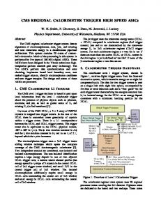
Figure 1. Sketch of the file-based HLT system. One the left, 2 BU appliances are shown. A builder-unit (BU) machine is connected to the event-builder network based on InfiniBand (IB). The filter-unit (FU) machines are attached to the BU via Ethernet. The latest generation machines have a 10 GbE connection using a 40 GbE uplink to the BU. Older generation machines will be connected with bonded 1 GbE links using legacy switches connected over 10 GbE to the 40 GbE uplink. On the right, the components of the storage and transfer system are shown. this approach inefficient. Therefore, ∼54 builder machines (BUs) will be connected to the eventbuilder network and write complete events to disk. Each BU has a statically allocated number of filter units (FUs). The FU machines mount the disk from the BU over a networking filesystem. They read the files from this disk and process them. The accepted events are written to the local disk. We call the unit consisting of one BU and its associated FUs an appliance (figure 1). Each appliance is a stand-alone unit with clear boundaries to the surrounding systems. It has a single function of building and filtering events. In addition, different hardware generations can work independently. In the future, it could be that some appliances provide additional features like GPUs or Xeon-Phi co-processors. The required throughput per BU is ∼2 GB/s at a level-1 trigger rate of 100 kHz. A standard harddisk cannot cope with this. Writing in parallel to SSD media was considered. However, as the lifetime of the media for our use case is questionable, we decided to use a RAM disk. A RAM disk of 256 GB would allow to buffer data for about 2 minutes or 4-5 luminosity sections of ∼23 s. The luminosity section is the smallest unit used for assessing the data quality in CMS. Events from different luminosity sections are written into separate files. In addition, multiple files are written per luminosity section. This is done for two reasons: firstly, the BU uses multiple threads to build and to write events independently, which results in one file per thread. Secondly, each HLT process reads one file at the time. Thus, having multiple files per luminosity section allows for a more efficient use of the FUs as each process quickly gets a file to work on. Each data file is accompanied by a meta-data file containing the number of events in the file. Additional meta-data files are written for each luminosity section and at the end of the run. We are using the JSON (JavaScript Object Notation) format which is lightweight, easily readable by humans and can be displayed on web pages for monitoring purposes. The control of the event-selection processes is also using the file system. At each run start, the BU creates a run directory containing the run number and the configuration for the HLT processes. A daemon discovers the creation of the run directory and starts the HLT processes. The daemon assures that the required resources are available, i.e. it does not start new processes if the FU is still processing data from a previous run, or if resources on the FU are allocated for other tasks, e.g. for running the CMS cloud. Once the HLT processes are started, they keep
3
20th International Conference on Computing in High Energy and Nuclear Physics (CHEP2013) IOP Publishing Journal of Physics: Conference Series 513 (2014) 012025 doi:10.1088/1742-6596/513/1/012025
looking for files to appear on the BU disk. When a HLT process grabs a file, the corresponding meta-data file is renamed. To avoid any race condition while renaming the file, a unique lock file is used. The HLT process stops processing events when all files have been grabbed and the end-of-run meta-data file from the BU has appeared. Each HLT process writes the accepted events to the local disk. Accepted events are sorted into different streams. One stream contains physics events, while up to 10 streams are used for different calibration events, data-quality monitoring, and other tasks. A separate file is written for each stream and luminosity section. For each output file, a meta-data file is created containing the number of processed and accepted events. In addition, a set of histograms used for online data-quality monitoring is written for each luminosity section . The bandwidth requirement per FU for the output is ∼3 MB/s, where we assume a 1 kHz HLT accept rate, an event size of 1 MB and a conservative factor 2 for calibration and monitoring data. However, the number of files created is daunting. In the worst case scenario where each core runs a separate process, up to 24 files are created per second and machine. This rate would be reduced by an order of magnitude if the currently being developed multi-threaded CMSSW framework [9] could be used for the HLT. 3.2. The Storage and Transfer System The files written to the local disks on the FUs by the HLT processes need to be aggregated. Thereby, the data belonging to one luminosity section and stream is treated separately and independently. The aggregation is done in 3 steps (see figure 1): (i) The data from all processes on one filter-unit is merged. The resulting files from each filter-unit are written to a disk local to the appliance, either in the BU machine or on a NAS. (ii) The data from all FUs attached to a given BU is merged. The resulting files are written to a global file system visible from all BUs. (iii) The final merge (mega-merger) takes the files from all BUs and merges them into a single file on a global file system. These files are then either copied to tier 0 for offline calibration and reconstruction, or made available to online calibration and monitoring applications. Each step starts as soon as new files appear. Once all input files are processed, they can be deleted. The meta-data files written by the BU and HLT processes are used to decide if all data has been processed. For example, all data for a given luminosity section has been processed when the event count of processed files as reported by the HLT processes matches the number of events written by the BU in this luminosity section. The requirement for the global file system used for the final merge is high. Each second, about 25 files are concurrently written from O(50) sources. The total bandwidth is ∼1 GB/s. These files need to be read by the final merge and the result written back to disk. Finally, the files have to be copied over to tier 0, or they are accessed by multiple online consumers. Therefore, a total read/write bandwidth of ∼5 GB/s from O(100) clients needs to be sustained. The total disk space of O(250 TB) will be similar to run 1. It allows to cache data for several days in case that tier 0 cannot digest the data. 4. Prototypes In order to evaluate the feasibility of the proposed file-based system and to test software and hardware solutions, 2 small-scale prototyping systems have been assembled (see figure 2). The BU appliance consists of a Dell R720 machine with 288 GB RAM acting as BU and 8 Dell C6220 machines mounting the RAM disk on the BU over 10 GbE using NFS 4. The appliance is connected over InfiniBand to 4 Dell C6220 acting as readout-units (RUs). Each RU emulates a fixed-size event fragment of 256 kB which is assembled by the BU and written to disk. The 4
20th International Conference on Computing in High Energy and Nuclear Physics (CHEP2013) IOP Publishing Journal of Physics: Conference Series 513 (2014) 012025 doi:10.1088/1742-6596/513/1/012025
RU
InfiniBand
10 GbE Data Backbone BU 256 GB RAM disk
I/O nodes
BU
BU
10/40 GbE switch
Mega Mergers
10 GbE FUs
Figure 2. Sketch of the 2 prototyping systems: on the left the prototype of the BU appliance connected to 4 readout units (RUs), on the right of the storage and transfer system. other prototype emulates the storage and transfer system: it consists of a number of machines emulating the output of a BU appliance, a cluster file system, and a few machines acting as merger nodes. 4.1. Prototype of the BU Appliance A first test performed on the BU-appliance prototype measured the writing performance. Figure 3 shows the measured throughput from 4 RUs to the BU. The event building and disk writing is done in a configurable number of threads. Each thread writes a fixed number of events into separates files on the 256 GB RAM disk mounted on the BU. The throughput rises linearly with the number of threads until it plateaus at about 5.2 GB/s when using 6 or more threads, which is well above the requirement of 2 GB/s. There is a small difference in throughput if the RAM disk is empty or 90% full. This is due to the fact the event building is done on one CPU and the memory for the RAM disk is preferentially allocated from the local memory. Only if the local memory is exhausted, the memory banks attached to the other CPU are used, which lowers the performance by ∼7%. The figure also shows that the event building can be done at 6.2 GB/s independently of the number of threads. However, it is expected that the event building will become more demanding when more RUs send smaller event fragments. The lower figure shows that the throughput is not affected by the number of files generated. For each data file, a meta data file is generated. It is interesting to note that even writing each event into its separate file has only a small affect on the throughput. In the test for the writing performance, the raw-data files are deleted either when the disk becomes full or immediately after closing. The next test uses HLT processes consuming the files. The HLT processes are started automatically by the HLT daemon who detects the appearance of the run directory. However, instead of doing real processing, the processes read the data and then sleep for a variable amount of time. They write ∼1% of the events accompanied by the corresponding meta data into 2 streams on the local disk. The meta data is used by a lightweight ruby-on-rails application server deployed in each machine. The server displays the status of the HLT processes on each FU node. The meta data is also aggregated by the server on the BU to summarise the data flow through the BU appliance. In future, this information will be used for aggregating the data files. Figure 4 shows the RAM disk usage over a simulated run. When the run starts, the data starts accumulating on the disk. After about 30 s, the first files have been processed by the HLT and are deleted. From then on, the disk usage stays constant while the BU continues to write at ∼3 GB/s. The small increase in disk usage seen in the figure is due to the meta-data and 5
20th International Conference on Computing in High Energy and Nuclear Physics (CHEP2013) IOP Publishing Journal of Physics: Conference Series 513 (2014) 012025 doi:10.1088/1742-6596/513/1/012025
Throughput (GB/s)
8 7 6 5 4 3 2 1 0
0
1
2
3
4
5
6
7
8
Throughput (GB/s)
Number of worker threads 8 7 6 5 4 3 2 1 0
9
10
Default setting
Requirement Building only 90% disk usage empty disk
1
10
100
1000
10000 100000 Default setting
Events per file
Figure 3. Measurement of the throughput to the RAM disk on the BU in the prototype system. The figure on the top shows the achievable throughput as number of worker threads. Each thread builds events from 4 sources and writes 2000 events into separate files. The lower figure shows that the throughput to disk using 8 worker threads is not affected by the number of events written into a single file.
RAM disk usage (%)
100 run starts
run stops
80 60 40 20 first files processed 0
0
60
120
180
all files done
240
300
360
420
480
540
600
Time (s)
Figure 4. The usage of the RAM disk over a simulated run (see text). The small increase in disk usage is due to meta-data files not consumed in this prototype. 6
20th International Conference on Computing in High Energy and Nuclear Physics (CHEP2013) IOP Publishing Journal of Physics: Conference Series 513 (2014) 012025 doi:10.1088/1742-6596/513/1/012025
monitoring files which are not yet processed by the downstream system in this prototype. Once the run stops, it takes another ∼30 s to finish the processing. It is also possible to start a new run immediately after the stop of the previous run in which case the processing of the new data starts while the remaining data is processed. 4.2. Benchmark for the Storage and Transfer System A benchmark has been developed which emulates the traffic of the final merge step. Several clients emulate the output of the BU appliance with fake data files. A simple merger aggregates these files. This benchmark is used to evaluate hardware solutions for the global file system. The benchmarks was tested on the run-1 legacy hardware [10] consisting of 8 Nexsan SATABeasts, each featuring 4 volumes. A Lustre filesystem (version 2.1 on SLC6) was set up on one of the volumes. The measured bandwidth merging (15 LS)·(10 streams)·(50 files) into (15 LS)·(10 streams)·(1 file) is 93.4 MB/s, corresponding to ∼3 GB/s when scaled to the full system. This is in agreement with previous tests and operational experience. The first real test system was provided by EMC Isilon. The x-series system consists of 4 NAS heads running the OneFS operating system and providing 42 TB of disk space. 3 clients are connected over 10 GbE using NFS 4. The measured throughput is ∼0.7 GB/s. Assuming a perfect scaling to the final system size, the throughput would be ∼4.2 GB/s. In addition to the marginal performance, the files written on one client appear in burst and with a noticeable delay on the other clients, which results in uneven CPU workload and disk access. Therefore, the OneFS which is designed for data protection rather than speed, is not the optimal solution for our needs. Systems from other vendors based on Lustre or GPFS (IBM) are being evaluated. 5. Summary A file-based high-level trigger system is an ambitious project. It is evaluated in the context of the new CMS data-acquisition system being constructed during the ongoing long shutdown of the LHC. The advance in network technology and the availability of affordable high-performance storage enables the decoupling of the data-flow software from the event-selection framework. The use of a file system provides a natural buffer space and resource arbitration, and it allows to run the HLT processes similar to offline jobs. We presented the concept of largely independent BU appliances doing the event building and filtering, and a global file system which is used to aggregate the data from the O(50) BU appliances. Prototypes of the most critical components have been developed to demonstrate the feasibility and to evaluate possible hardware solutions. No show-stoppers have been identified. However, many issues concerning the scalability, reliability, and error recovery have still to be addressed. Acknowledgments This work was supported in part by the DOE and NSF (USA) and the Marie Curie Program. References [1] [2] [3] [4] [5] [6] [7] [8] [9] [10]
Adolphi R et al. (CMS Collaboration) 2008 JINST 3 S08004 Lange D J (CMS Collaboration) 2011 J.Phys.Conf.Ser. 331 032020 Mommsen R K et al. 2011 J.Phys.Conf.Ser. 331 022021 Petrucci A et al. 2012 J.Phys.Conf.Ser. 396 012039 Holzner A et al. 2013 in these proceedings InfiniBand Trade Association, see http://www.infinibandta.com Spataru A et al. 2012 J.Phys.Conf.Ser. 396 012008 Gutleber J et al. 2010 J.Phys.Conf.Ser. 219 022011 Jones C and Sexton-Kennedy E 2013 in these proceedings Mommsen R K et al. 2010 J.Phys.Conf.Ser. 219 022038
7