Abstract-Strained layer InGaAs-GaAs single-quantum-well buried ... L. Eng, B. Zhao, S . Sanders, and A. Yariv are with the Department of. Applied Physics ...
1183
IEEE JOURNAL OF QUANTUM ELECTRONICS, VOL. 26, NO. 7, JULY 1990
Submilliamp Threshold InGaAs-GaAs Strained Layer Quantum-Well Laser T. R. CHEN, L. ENG, B. ZHAO, Y. H. ZHUANG, S. SANDERS, H. MORKOC, FELLOW,IEEE, A N D AMNON YARIV, FELLOW, IEEE
Abstract-Strained layer InGaAs-GaAs single-quantum-well buried heterostructure lasers were fabricated by a hybrid molecular beam epitaxy and liquid phase epitaxy technique. Very low threshold currents, 2.4 mA for an uncoated laser ( L = 425 pm) and 0.75 mA for a coated laser ( R 0.9, L = 198 pm), were obtained. A 3 dB modulation bandwidth of 7.6 GHz was demonstrated at low bias current (14 mA).
-
I. INTRODUCTION
I
nGaAs-GaAs strained layer quantum-well lasers have been the subject of considerable recent interest [1]-[8]. The strained layer structure offers a new degree of freedom for valence band engineering, resulting in a potentially lower threshold and wider modulation bandwidth compared with conventional lattice-matched material quantum-well lasers [9]-[13]. Theoretical analysis predicted a threshold current density as low as 43 A/cm2 and a 3 dB cutoff frequency as high as 90 GHz [ l l ] . Broadarea threshold current density of 174 A/cm2 and threshold current of 12 mA on a stripe laser structure were achieved [ 141. A threshold current of less than 7 mA was demonstrated in buried heterostructure [ 151. A high-power output in excess of 200 mW was reported in an array configuration [16]. A continuous wave (CW) operation life time exceeding 5000 h was reported 1171, showing encouraging reliability. In addition to these attractive features, the wavelength of InGaAs-GaAs laser falls into the range of X = 1 pm (from X = 0.87 pm [16] to X > 1 pm [15], e.g.), which fills up the wavelength gap between GaAlAs-GaAs and GaInAsP-InP lasers. This opens up potential applications in certain circumstances such as optical pumping of some rare-earth solid-state lasers [ 161. However, the present stage of the laser performance is still far from the theoretical expectation, and the highspeed modulation experiment has not been reported so far. In this paper, we report on the substantial reduction of the threshold current of InGaAs-GaAs lasers. High-speed modulation is demonstrated for the first time. CW threshold current as low as 2.4 mA (for an uncoated laser) and
Manuscript received October 27, 1989; revised February 21, 1990. This work was supported by the Defense Advanced Research Projects Agency and the Office of Naval Research. The work of S . Sanders was supported by a National Science Foundation Graduate Fellowship. T . R. Chen and Y. H. Zhuang are with the University of Electronic Science and Technology, China. L. Eng, B. Zhao, S . Sanders, and A . Yariv are with the Department of Applied Physics, 128-95, California Institute of Technology, Pasadena, CA 91125. IEEE Log Number 903599 1 .
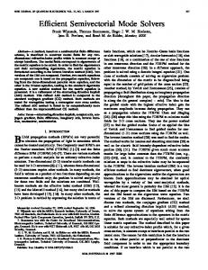
0.75 mA (for a coated laser), and a 3 dB bandwidth of 7.6 GHz were achieved. A systematic study of the device performance and some related material properties are presented. In Section 11, we introduce the procedures for material preparation and device fabrication. The performance of the lasers is summarized in Section 111. In Section IV, we describe the effect of dielectrical coating on the laser performance. The high-frequency direct current modulation results are presented in Section V. 11. STRUCTURE A N D FABRICATION The laser used for this study is a buried heterostructure (BH) graded index separated confinement heterostructure (GRIN-SCH) single-quantum-well (SQW) strained layer (STL) InGaAs-GaAs laser. The fabrication of the laser involves two-step crystal growth. The GRINSCH-SQWSTL material was prepared by the molecular beam epitaxy (MBE) technique. The BH laser structure was accomplished by utilizing the liquid phase epitaxy (LPE) regrowth technique. In the first step, a laser structure was grown on a GaAs (100) substrate tilted 4 " towards the (1 11) direction. The structure consists of 1 pm GaAs buffer layer, 1.5 pm Al,Gal _,As cladding layer ( x = 0 . 5 ) , 0.15 pm GRIN 0.2, 40 A GaAs spacer, 50 region with x = 0.5 InGaAs quantum well, 40 GaAs spacer, 0.15 pm GRIN regionlx = 0.2 0 . 5 ) , 1.5 pm Alo.5Gao,5Aslayer, and 2000 A GaAs cap layer. The MBE growth was carried out in a Riber 2300 R&D system. The substrate temperature was held at 600°C for the GaAs buffer and cap layers, 720°C in the cladding and graded regions, and ramped down during the GaAs spacer growth to about 620°C for the InGaAs quantum well. The temperatures quoted are obtained pyrometer readings. To accomplish the large substrate temperature differences necessary for high-quality AlGaAs and InGaAs growths, we have used an indium-free mounting technique thereby reducing the thermal mass of the sample and allowing for continuous growth without interruption. The indium mole fraction in the InGaAs quantum well is estimated to be larger than 35% from the photoluminescence spectrum (Fig. 1) of the grown wafer 181. The accurate amount of In incorporated into the quantum well is difficult to state, however. The GRINSCH-SQW-STL structure is shown in Fig. 2. After MBE growth, mesas were chemically etched on the wafer and the width of the active layer was 2 um. The -+
A
-+
0018-9197/90/0700-1183$01.OO @ 1990 IEEE
A
1184
IEEE JOURNAL OF QUANTUM ELECTRONICS, VOL. 26, NO. 7, JULY 1990
1
h l = 1.006 pm h2 = 1.184 pm
GRIN SCH SQW
structure
//
,B:AIG.XAS,
n *-GaAs substrate
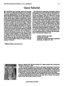
Fig. 3. A schematic structure of the BH InGaAs-GaAs lasei.
0.95 A1
50.0nm/D
1.2
1.45
A2
Wavelength (pm) Ith(mA)
Jkh (A/cm2)
rld(mW/mA)
3976
9.5
121
0.19
2385
6.5
136
0.25
1676
5.8
173
0.34
0 2pm p+GaAs 1 5~ P-GW 4 0 0 2pm graded p Ga,, ,AI, f i s + Ga,, ,AI, ,As
1590
5.6
176
0.36
1004
4.2
209
0.33
923
4.0
217
0.40
40A GaAs %A In,Ga,-,As 40A GaAs 0 2pm graded nGa,, ,AI, ,As+G~,Al,
613
3.7
302
0.43
425
2.4
294
L
Fig. 1. Photoluminescence spectrum of an MBE grown InGaAs strained layer single-quantum-well wafer.
(vm)
304
I
I
2.8
I
1
461
I
I
0.41 0.35
+s
1 5 p n n-Ga,, ,AI, ,As
0 S p n n+-GaAsBuffer
t-
c
0.5
Fig. 2 . A schematic of the GRINSCH-SQW-STL InGaAs material
wafer was then cleaned and the top GaAs cap layer was removed immediately prior to loading the wafer into an LPE system for regrowth. The regrowth temperature was 800°C. A p-Alo,4Gao.6Aslayer and an n-Alo,4Gao.6Aslayer were grown successively to form a blocking junction. After the second regrowth, the wafer was processed into BH lasers, using conventional fabrication techniques. The processes include thermal deposition of S O 2 , photolithography for a stripe contact opening, shallow Zn-diffusion, contact metalization, and annealing. The Zn-diffusion is an important step to improve the ohmic contact and reduce contact resistance as we do not have a heavilydoped GaAs cap layer on the top of the device. A schematic of the finished device is shown in Fig. 3. 111. PERFORMANCE OF THE LASERS A . Threshold, Spectrum and Far Field To test the performance of the lasers, the wafer was subsequently cleaved into laser bars of various cavity lengths. The laser chips were mounted on Cu blocks for CW operation. Light versus current (L-Z ) characteristics were measured under CW conditions and very low threshold currents were observed. Some of the measured thresh-
-
2175
0.27
3632
0.28
n+-GaAssubstrate
AI content in Ga,.$l,As
0.0
117
old currents ( Zth) along with their respective cavity lengths ( L ) are listed in Table I. It can be seen from the table that the lowest threshold current obtained is 2.4 mA for a laser of cavity length 425 pm. To the best of our knowledge, this is the lowest figure ever reported to date for this material system and is also among the best results for uncoated semiconductor lasers. The lowest threshold current density was 120 A/cm* for a 3976 pm long laser. Considering that this value is deduced from a BH laser, which may introduce additional carrier and optical losses comparing with broad area lasers, we expected even lower threshold current densities for broad area lasers. Indeed, a threshold current density of 114 mA/cm2 was measured 1540 pm long, 100 pm wide broad contact for a GRINSCH-SQW-STL laser. The lasing wavelength for the uncoated device is about 0.93 pm (for a cavity length of = 250 pm). Photographs of the spectra are shown in Fig. 4. The spectra shown were obtained from the same laser with different mirror reflectivities. The reason for the lasing wavelength shift will be discussed later in Section IV-C. The lasing wavelength also depends on the cavity length. It becomes longer for longer cavity length. For a 1540 pm long broadarea laser, a lasing wavelength of 0.99 pm was measured. The laser is capable of delivering an optical power in excess of 80 mW under pulsed operation (for a laser of 1676 pm cavity length). The L-Z curve of this laser is shown in Fig. 5.
-
CHEN et
U/.:
1185
STRAINED LAYER QUANTUM-WELL LASER
80
70
60
50 L
a
3
0
a .2 c
40
8 30
20
10
Wavelength
(p)
Fig. 4. Emission spectra of InGaAs-GaAs laser ( L = 250 pin. signal power level is about 5 m W ) . Top: for mirror reflectivity R , = RZ = 0.3. Bottom: for mirror reflectivity R , = 0.3, Rz = 0.9.
The lasers are found to operate in fundamental transverse mode, and a far-field pattern parallel to the junction plane is shown in Fig. 6. The beam divergence, full width at half maximum (FWHM), is about 18". In Fig. 7, a histogram of over 80 lasers, showing the dependence of threshold currents on cavity lengths, is presented. The threshold current of the laser decreases with cavity length for L L 1 mm up to the longest laser, L = 4 mm, measured, and is substantially a constant over the range 300 pm IL 5 1000 pm (1 mm), then increases steeply with further decrease of the cavity length. The observed increase at small cavity lengths is mainly related to the gain saturation behavior of single-quantum-well structure. The observed cavity length dependence of the threshold current is consistent with the theoretical result [I81
or
0 50
150
200
250
300
350
400
450
Injection Current (mA) Fig. 5. L-I characteristic of an InGaAs-GaAs SQW laser, showing an output power of 80 mW.
-60-40-20 0 20 40 60 Degree
Fig. 6 . A typical far-field pattern of an InGaAs-GaAs laser at different power level, showing stable single-transverse-mode operation.
tor, R I = R2 = R are mirror reflectivities, L is the cavity length, W is the active layer width, I' is the optical confinement factor, and Go is the gain constant. Equation (2) shows that the threshold currents should increase with decreasing cavity length for very short lasers. A theoretical It,, - L curve with Jo = 120 A/cm2, I'G, = 30 cm-', R = 0.3 is also shown in Fig. 7. The experimental data follow the general trend of the theoretical curve fairly well, although the measured threshold currents seem somewhat higher than the calculated values.
B. qd
where Jthis the threshold current density, Jo is the transparency current density, CY, is the internal optical loss fac.
100
- L Relation The external quantum efficiency of the BH InGaAsGaAs SQW laser was measured under CW conditions. The best results obtained so far are 0.47 mW /mA Der facet
1186
IEEE JOURNAL OF QUANTUM ELECTRONICS, VOL. 26, NO. 7, JULY 1990
a 0.5E
2C
._ 0 r
5
. i.. !
I
I
... . .. . . .. .
..
02-
.
I
#
.
. .
0.3 -
5
gm
,.. . .. ..... . I
2 0 4 -
..
I
.
E
e
0.1
I
I
I
0 100200300400500
I
I
I
1000
1500
2000
2500
Cavity Length L (pm)
Fig. 8. External quantum efficiency as a function of cavity length
Cavity Length (p) Fig. 7. The distribution of threshold currents against cavity lengths and a theoretical Ich-Lcurve with Jo = 120 A/cm2, rGo = 30 c m - ' , a, = 3 cm-'. R = 0.3.
(or 35% per facet) for a laser of 587 pm cavity length, and 0.52 mW /mA ( = 39% ) per facet for a 289 pm long laser. The external quantum efficiency qd of the laser was a function of cavity length L. When the cavity length decreases, v d first increases similar to the case for conventional (nonquantum-well) semiconductor laser. However, at some point, v d reaches its maximum and then decreases rapidly with further decrease of the cavity length. The measured values of ?,?d for lasers of various cavity lengths are shown in Fig. 8. Some experimental data are also listed in Table I. The rapid decrease of the external quantum efficiency at short cavity length is not predicted by the conventional semiconductor laser theory. The underlying physics is similar to that described in the previous paragraph. In short cavity lasers, the requirement for higher threshold gain causes a rapid increase in threshold carrier density. This, in turn, increases various kind of nonradiative recombination process such as Auger recombination [ 191, L-valley recombination [20], and carrier leakage over the heterostructure barrier [2 13 resulting in a decrease of the internal quantum efficiency vi. In addition, the increased threshold current in very short cavity lasers results in a higher operation voltage which increases the leakage currents (e.g., the leakage current through the reverse biased blocking junction), causing a further decrease of the internal quantum efficiency.
C. Internal Loss Factor aiand Internal Quantum Eficiency 7; It is evident from Table I, Fig. 7, and Fig. 8 that the lasing threshold current and the external quantum efficiency display a weak dependence on the cavity length when the latter varies from -300 pm to 1 mm, indicating a very low internal loss of the lasers. It is thus interesting to determine the internal loss factor ai and the internal quantum efficiency v i .
-
I
I
I
I
100
200
300
400
I
I
I
500
600
700
I 800
1 900
1 1000
1
1
1100
1200
Cavity Length L (pm)
Fig. 9. An experimental plot of 7;' versus L , showing a,= 3.1 c m - ' and 7, = 0.78.
The standard technique for experimental determination of v i and aiutilizes the linear relation between 1/ v d and L [22]. However, for our SQW lasers, this relation does not hold for short cavity lasers as described previously. We measured 1 /vd-L dependence for lasers subsequently cleaved from the same stripe and found that the linear relation was followed pretty well for L > 300 pm. ai and vi were measured this way for lasers from different stripes. The values of ai were found in the range of 3-10 cm-', and v i ' s were 60-80%. It should be noted that the a; and vi were measured in a realistic laser structure. The internal loss ai includes the free carrier absorption which should be very small ( 1-2 cm-') in a SQW structure due to low optical confinement, the absorption in the cladding layers and the waveguide scattering loss. q i is governed by various kinds of leakage currents and nonradiative recombination processes. The measured ai and v i showed the high quality of the material as well as the device. A 1/qd-L curve showing ai5: 3.1 cm-l and v i = 0.78 is presented in Fig. 9.
1187
CHEN et al.: STRAINED LAYER QUANTUM-WELL LASER
IV. LASERPERFORMANCE A N D MIRROR REFLECTIVITIES A. Coating and Zth The ,very low internal loss of the laser results in a weak dependence of the threshold current and the external quantum efficiency on laser cavity length. It also suggests that for standard ( 250 p m ) and short cavity lasers the uncoated mirror loss be dominant over the internal loss. One can then expect a substantial reduction in lasing threshold current with reduced mirror losses. In fact, the threshold modal gain gth of a semiconductor laser can be written as 1 1 gth = ai - In (3) 2L R1R2
-
+
where R I and R2 are mirror reflectivities. Shown in Table I1 is a comparison of the loss terms on the right-hand side of (3) for various cavity lengths .and mirror reflectivities. It is clear that for our InGaAs-GaAs lasers, with uncoated mirrors ( R I = R2 = 0.3 ), even for cavity lengths as large as 1000 pm, the mirror loss is still larger than the internal propagation loss. Also seen is for L = 250 pm and ai= 3 cm-I, R I and R2 must be higher than 0.95 in order for the threshold to be dominated by the internal loss. The conclusion is that due to the very low internal loss, highreflectivity coating will reduce the threshold current substantially even in long cavity lasers. However, in order to take full advantage of the low loss to reach ultralow threshold, short cavity lasers are preferable ( L < 100 pm, e.g., ). In this case, the mirror reflectivities of R > 0.95 or even higher should be used. Different coatings were applied to lasers with different lengths. In all cases, high reflectivity coatings led to a reduction of the threshold current. Some of the typical results are listed in Table 111. The L-I curves for laser #3 are presented in Fig. 10. The laser was 198 pm long. The threshold current was 3.8 mA with uncoated facets. After the mirrors were coated to R = 0.9, a threshold current as low as 0.75 mA was obtained.
TABLE I1 A COMPARISON OF THE INTERNAL PROPAGATION Loss CY, A N D THE DISTRIBUTED MIRROR Loss ( 1/ 2 L ) In ( 1 / R , R,) FOR DIFFERENT MIRROR REFLECTIVITIES A N D CAVITY LENGTHS
1
+l
500
I
24.0
1
7.13
I
2.10
1.02
I
6
250
48.0
3
14.3
4.21
I
2.05
I
I
120
35.7
10.5
5.13
240
71.4
21.1
1 10 0. .3 3
6
50
'1
TABLE 111 MEASURED THRESHOLD CURRENT It,,,EXTERNAL QUANTUM EFFICIENCY qd AND WAVELENGTH h AS A FUNCTION OF MIRROR REFLECTIVITIES R , , R, AND CAVITY LENGTH L
I
,25
0.3 011
0.3
3
198
09
I I
0.3 011
I
I
I I
0.3 03
I I
I
1.0
I
041 0 22
3.8 23
I 1
0.37 071
2.1
I
0.925
10947
B. Coating and External Quantum E@ciency A very important consequence of the low internal loss is a weak dependence of the external quantum efficiency on the mirror reflectivities. For different ai values, the dependence of q d on R ( = R I = R 2 ) with constant q i is depicted in Fig. 11. It is clear that for larger a i L , e.g., ai = 40 cm-I and L = 200 pm, q d drops very fast when the mirror reflectivity increases. However, for small aiL,q d does not change considerably even when R increases from 0.3 to 0.9. Therefore, the very low internal loss of the InGaAs-GaAs laser makes it possible to produce submilliamp lasers by using high-reflectivity coating and at the same time to maintain reasonably-high external quantum efficiencies and appreciable output powers. The experimental data are consistent with the calculated results depicted in Fig. 11. Some of the measured q d for lasers with different coatings are presented in Table 111.
Fig. 10. L-Z characteristic of a low threshold InGaAs-GaAs laser ( L = 198 p m ) with different mirror reflectivities R , , R2.
IEEE JOURNAL OF QUANTUM ELECTRONICS, VOL. 26. NO. 7, JULY 1990
1188
Fu
0.5
1
1 I
C I
V. DIRECTCURRENT MODULATION A direct current modulation was performed on a laser with both facets coated to R = 0.8. The threshold current of the laser was 1.3 mA. The cavity length was 200 pm. To facilitate high-frequency operation, a 10 pm wide mesa was etched around the active region to reduce the parasitic effect. When the laser was biased to 1 mA above threshold, a corner frequency of 1.8 GHz and a 3 dB bandwidth 2.8 GHz was measured as shown in Fig. 13(a).The of output power of the laser at this bias current was 0.2 mW. For this laser, a 3 dB bandwidth of 5.5 GHz was measured at a bias current of 6.3 mA. For another laser ( I t h = 1.5 mA), at a bias current of 14 mA, a 3 dB bandwidth of 7.6 GHz was observed. The modulation experiments showed that the strained layer InGaAs-GaAs lasers are indeed fast, especially at injection levels slightly above threshold. Although the speed of the laser is at least comparable with the reported results for its AlGaAs-GaAs counterpart [24],no significant enhancement of the modulation bandwidth has been observed. The limited maximum bandwidth in our experiment is believed to be caused by the parasitic capacitance. Further work is needed before we can properly compare the experimental results with the theoretical prediction.
-
3
0.0
0.2
0.4
0.6
1 .o
0.8
Mirror Reflectivity R Fig. 11. External quantum efficiency with constant 7,as a function of mirror reflectivity R , = RZ = R for different internal loss a,values.
I
li"< A' Wavelength
Fig. 12. Schematic gain spectra at threshold for different mirror reflectivities, showing different lasing wavelengths.
C. Lasing Wavelengths as a Function of Mirror Reflectivities The control of mirror reflectivity has been found to be an effective way to tune the lasing wavelength of semiconductor lasers [23].The physical mechanism for wavelength tuning by mirror coating is as follows. Facet coatings determine the effective distributed mirror loss 1/ L In 1/R of the laser and thus the threshold modal gain [see (3)].In semiconductor lasers, the gain spectrum has a nonsymmetric feature. Shown in Fig. 12 are two gain spectra at threshold corresponding to different mirror reflectivities R' > RI'. The threshold gain g t h ( R ' ) is smaller than g t h ( R " ). Therefore the corresponding lasing wavelength A' is longer than A". It is obvious that the change in threshold gain and thus the lasing wavelength will be more pronounced if the internal loss aiis smaller, assuming the same amount of change in mirror reflectivities. This is exactly the case in the present InGaAs-GaAs lasers. Some of the measured wavelengths of lasers with different coatings can be found in Table 111. It was noted that by changing the mirrors' reflectivity R from 0.3 to 0.9,lasing wavelength y a s changed from 0.92 to 0.96pm (AA = 400 A ). This variation is much more pronynced than in conventional InP lasers (AA =
-
150 A ) [23].
-
-
VI. CONCLUSION In conclusion, strained layer InGaAs-GaAs GRINSCH SQW lasers were fabricated by a hybrid MBE and LPE techniques. Very low threshold currents, 2.4 mA for the uncoated laser ( L = 425 pm) and 0.75mA for the coated laser ( L = 198 pm), were obtained. The lasing wave0.93 pm for uncoated lasers. External length was quantum efficiency as high as 0.52 mW/mA per facet (L 300 p m ) and an output power of over 80 mW ( L = 1.68mm) were observed. A modulation bandwidth of 7.6 GHz was demonstrated at low bias current. The very low internal loss of the laser results in a weak dependence of I t h and qd on the cavity length (for not very short cavity lasers) and a weak dependence of q d and output power on the mirror reflectivity. It also offers an effective way to tune the threshold current and lasting wavelength by facet coating. Because of these features this laser is attractive for applications which require a combination of low threshold, high speed, high quantum efficiency, and reasonable output powers.
-
-
ACKNOWLEDGMENT
T . R. Chen would like to thank J. Paslaski for helpful discussions on high-frequency modulation. The authors are also grateful to D. Armstrong for his help in many ways during the LPE growth process. REFERENCES [ l ] M. D. Camras, J . M . Brown, N . Holonyak, J r . , M. A . Nixon, R. W. Kaliski, M. J . Ludowise, W. T. Dietze, and C. R. Lewis,
1189
l2
t
0.045
1 1
2
3
4
5
6
7
8
9
10
0.045
-,Frequency (GHz)
Ith = 1.5 mA
1
2
3
4
5
6
7
8
9
10
Frequency (GHz)
(a) (b) Fig. 13(a). Frequency response of a low threshold InGaAs-GaAs laser, showing comer frequencyf, = 1.8 GHz at a bias current I = 2 . 3 mA. Cavity length L = 200 pm, threshold current I,, = 1.3 mA, and mirror reflectivities R , = Rz = 0.8. (b) Frequency response of a low threshold InGaAsGaAs laser, showing 3 dB bandwidthf, = 7.6 GHz at a bias current I = 14 mA.
“Stimulated emission in strained-layer quantum well heterostructures,” J . Appl. Phys., vol. 54, pp. 6183-6189, 1983. [2] N. G. Anderson, Y. C . Lo, and R. M. Kolbas, “High-efficiency carrier collection and stimulated emission in thin (50 A ) pseudomorphic In,Ga, ,As quantum wells,” Appl. Phys. L e t t . , vol. 49, pp. 758760, 1986. [3] W . D. Laidig, P. J . Caldwell, Y. F. Lin, and C . K. Peng, “Strainedlayer quantum-well injection laser,” Appl. Phys.Lett., vol. 44, pp. 653-655, 1984. [4] W . D. Laidig, Y. F . Lin, and P. J . Caldwell, “Properties of In,Ga, As-GaAs strained-layer quantum-well-heterostructure injection lasers,” J . Appl. P h y s . , vol. 57, pp. 33-38, 1985. [ 5 ] D. Feketa, K. T . Chan, J . M. Ballantyne, and L. F. Eastman, “Graded-index separate-confinement InGaAs/GaAs strained-layer quantum well grown by metalorganic chemical vapor deposition,” Appl. Phys. Lett., vol. 49, pp. 1659-1660, 1986. [6] S . E. Fischer, D. Fekete, G. B. Feak, and J . M. Ballantyne, “Ridge waveguide injection laser with a GaInAs strained-layer quantum well ( X = 1 p m ) , ” Appl. Phys. Lett., vol. 50, pp. 714-716, 1987. [7] Y. J . Yang, K. Y. Hsieh, and R. M. Kolbas, “Continuous roomtemperature operation of an InGaAs-GaAs-AIGaAs strained layer laser,” Appl. Phys. Lett., vol. 51, pp. 215-217, 1987. [8] R. M. Kolbas, N . G. Anderson, W . D. Laidig, Y. Sin, Y. C . Hsieh, and Y. J . Yang, “Strained-layer InGaAs-GaAs-AIGaAs photopumped and current injection lasers,” IEEE J . Quantum Electron., vol. 24, pp. 1605-1613, 1988. [9] A. R. Adams, “Band-structure engineering for low-threshold highefficiency semiconductor lasers,” Electron Lert., vol. 22, no. 5 , pp. 249-250, 1986. [ l o ] E. Yablonovitch and E. 0. Kane, “Reduction of lasing threshold current density by lowering of valence band effective mass,” J . Lightwave Technol., vol. LT-4, pp. 504-506, 1986. [ I l l I . Suemune, L. A. Coldren, M. Yamanishi, and Y . Kan, “Extremely wide modulation bandwidth in a low threshold current strained quantum well laser,” Appl. Phys. L e f t . , vol. 53, no. 15, pp. 1378-1380, 1988. [12] T. C . Chong and C . G. Fonstad, “Theoretical gain of strained-layer semiconductor lasers in the large strain regime,” IEEE J . Quantum Electron., vol. 25, pp. 171-178, 1989. [13] E. P. O’Reilly, “Valence band engineering is strained-layer structure,” Semicond. Sci. Technol., vol. 4 , pp. 121-137, 1989. [I41 S . D. Offsey, W. J . Schaff, P. J . Tasker, H . Ennen, and L. F. Eastman, “Strained-layer InGaAs-GaAs-AIGaAs graded-index separate confinement heterostructure single quantum well lasers grown by molecular beam epitaxy,” Appl. Phys. Lett., vol. 54, pp. 2527-2529, 1989. 1151 P. K. York, K. J . Beernink, G. E. Fernandez, and J . J . Coldren, “InGaAs-GaAs stained layer quantum well buried heterostructure lasers ( A > 1 p n ) by metalorganic chemical vapor deposition,” Appl. Phys. L e t t . , vol. 54, pp. 499-501, 1989. ~
~
[16] W . Stutius, P. Gavrilovic, J . E . Williams, K. Meehan, and J . H . Zarrabi, “Continuous operation of high-power (200 m W ) stainedlayer Ga, ,In,As/GaAs quantum well lasers with emission wavelength: 0.87 pm s X s 0.95 pm,” Electron. L e t t . , vol. 24, no. 24, pp. 1493-1494, 1988. [I71 S . E. Fischer, R. G. Waters, D. Fekete, J . M . Ballantyne, Y. C. Chen, and B. A. Saltz, “Long-lived InGaAs quantum well lasers,” Appl. Phys. Lett., vol. 54, pp. 1861-1862, 1989. [18] P. W . A. McIlroy, A. Kurobe, and Y. Uematsu, “Analysis application of theoretical gain curves to the design of multi-quantum-well lasers,” IEEE J . Quantum Electron., vol. QE-21, pp. 1958-1963, 1985. 1191 R. I . Taylor, R. A. Abram, M. G. Burt, and C . Smith, “Auger recombination in a quantum-well-heterostructure laser,” Proc. IEEE, vol. 132, Pt. J , pp. 364-370, 1985. [20] A. Sugimura, “Threshold currents for AlGaAs quantum well lasers,” IEEE J . Quantum Electron., vol. QE-20, pp. 336-343, 1984. [21] C. M. Wu and E. S . Yang, “Physical mechanisms of carrier leakage in DH injection lasers,” J . Appl. P h y s . , vol. 49, pp. 3114-3117, 1978. 1221 H. C . Casey Jr. and M . B. Panish, Heterostructure Lasers, part A: Fundamental Principles, Orlando, FL: Academic Press. 1978. [23] T . R. Chen, Y. H. Zhuang, P. L . D e n y , and A. Yariv, “The application of dielectrical coating to semiconductor lasers,” unpublished. [24] P. L. Deny, T . R. Chen, Y. H . Zhuang, J . Paslaski, M. Mittelstein, K. Vahala, A. Yariv, K. Y . Lau, N. Bar-Chaim, “Properties of ultra low threshold single quantum well (AI, Ga)As lasers for computer interconnects,” Optoelectronics-Devices and Technol. , vol. 3, no. 2 , pp. 117-130, 1988. ~
T. R. Chen, photograph and biography not available at the time of publication.
L. Eng, photograph and biography not available at the time of publication. B. Zhao, photograph and biography not available at the time of publication.
Y. H. Zhuang, photograph and biography not available at the time of publication.
S. Sanders, photograph and biography not available at the time of publication.
H. Morkoc (S’72-M’76-SM’79-F’87), available at the time of publication.
photograph and biography not
IEEE JOURNAL OF QUANTUM ELECTRONICS, VOL. 26, NO. 7. JULY 1990
1190
Amnon Yariv (S’56-M’59-F’70), a native of Israel, obtained the B . S . , M.S., and Ph.D. degrees in electrical engineering from the University of California, Berkeley, in 1954, 1956, and 1958, respectively. He joined Bell Telephone Laboratories, Murray Hill, NJ, in 1959, at the early stages of the laser effort. He came to the California Institute of Technology, Pasadena, in 1964 as a Associate Professor of Electrical Engineering, becoming a Professor in 1966. In 1980 he become the Thomas G . Myers Professor of Electrical Engineering and Applied Physics. On the technical side, he took part (with various co-workers) in the discovery of a number of early solid-state laser systems, in proposing and demonstrating
semiconductor based integrated optics technology, and in pioneering the field of phase conjugate optics. His present research efforts are in the areas of nonlinear optics, semiconductor lasers, and integrated optics. He has published widely in the laser and optics fields some 300 papers and has written a number of basic texts in quantum electronics, optics, and quantum mechanics. He is also a founder and chairman-of-the-board of the Ortel Corp., Alhambra, CA. Dr. Yariv is a member of the American Physical Society, Phi Beta Kappa, the American Academy of Arts and Sciences, and the National Academy of Engineering, and a Fellow of the Optical Society of America. He received the 1980 Quantum Electronics Award of the IEEE, the 1985 University of Pennsylvania Pender Award, and the 1986 Optical Society of America Ives Medal.