networks based on the P2P protocol with a decentralized directory. The context of ..... queue NETWORK pointer in the definition phase of connections among the.
TASK QUARTERLY 11 No 3, 203–235
QUEUE-BASED SIMULATORS OF P2P NETWORKS LEONARDO PASINI AND SANDRO FELIZIANI Departments of Mathematics and Computer Science, University of Camerino, Madonna delle Carceri, 62032 Camerino, Italy {leonardo.pasini, sandro.feliziani}@unicam.it (Received 5 August 2006) Abstract: A technique is introduced for the construction of simulators of telecommunication networks based on the P2P protocol with a decentralized directory. The context of the application concerns P2P networks used both by sharing software and by telecommunication applications, as in VoIP applications. P2P systems have the advantages of boundless scalability and the break-up insensibility of devices, but suffer from heavy traffic of signals and network delays. Therefore, simulation of signal traffic in P2P networks is an important issue. The technique we have developed enables individuation of a generic P2P network’s components and their functional characterization. We have worked at this level of description in order to determine the architecture of every component as a model of queues’ networks. We have therefore defined a library of new types of objects for the construction of P2P network simulators with the Qnap2.V9 programming language. In this context, we have defined a procedure automatically generating the simulator of an any P2P network. During its execution, the procedure reads data from a file containing a description of the structure of the considered P2P network and values of the characteristic parameters of its components. Results related to the simulation of three configurations of a P2P network are introduced in Section 5 below. They differ according to the technology used to realize the local interconnection networks. The context of the present paper is a research program developed at the University of Camerino in defining specific computer procedures aimed at construction of simulators of telecommunication and computing networks. This technique also enables simulation of the software elaboration phases on computer networks and evaluation of the impact of specific choices concerning the structure of transmission protocols and operation paradigms of software applications [1, 2]. Keywords: computer science engineering, queuing system networks, computer networks simulation, communication system protocols, Voice over Ip networks
1. Introduction Peers of a P2P telecommunication network are hosts capable of acting as client and as server at the same time. While a peer can act as a server to send contents to another remote peer, it can also work as client and receive contents from the same peer. In a decentralized-directory P2P protocol, every participant peer is both a distributor and a consumer of contents. The P2P file sharing system is a paradigm of versatile sharing of contents; all contents is directly transferred among normal peers, without
TQ311C-E/203
30 IX 2008
BOP s.c., http://www.bop.com.pl
204
L. Pasini and S. Feliziani
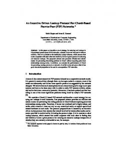
passing through a third-party server. A P2P system exploits the band, memory and CPU resources of a multiplicity of peers to distribute contents. Sharing P2P files is broadly scalable. Although no third-party centralized server participates in file transfers, the peer to peer file sharing uses the client-server paradigm prevailing in the Internet. In this context, the applicant peer is a client, while the recipient peer of the application is a server. The file is sent by the server peer to the client peer through a protocol of file transferring. As all the peers of a P2P network can send applications and receive applications, they have to be able to activate both the client side and the server side of the file transferring protocol. In the P2P file sharing system, there usually exists a large number of connected peers, and every peer can have objects to share online, e.g. audio files, video files, images and programs. If a peer is interested in getting a particular object, it has to have a way of determining the IP addresses of peer connected to the P2P network having a copy of the desired object. A structural scheme of a P2P network is shown in Figure 1. The connection links among the network’s peers point out to the presence of a logical channel of connection. One can see that a number of peers in the schema is individualized as group leaders.
Figure 1. Schema of a P2P network (decentralized directory)
When a peer is connected to a P2P application, it is assigned to one of the P2P network’s group-leaders. Having learnt the IP address of its group leader, the peer contacts the leader and informs it about the contents it is about to share online. The group leader keeps a database of contents and the corresponding IP addresses for peers that have been assigned to its group. In this context, a group leader of a P2P network is a normal peer, not a dedicated server. When a peer wants to locate a particular object, it sends an application to its group leader, who responds by sending a list of its group peers possesing the object.
TQ311C-E/204
30 IX 2008
BOP s.c., http://www.bop.com.pl
Queue-based Simulators of P2P Networks
205
The leader can also contact other group leaders asking them to send lists of peers which posses the required object. Through this mechanism, the applicant peer obtains IP addresses of many peers connected to the P2P network possessing the required object. The peers and their logical relationships of communication form an abstract logical network, called an overlay network. The nodes of an overlay network are peers, and there is a connection between every peer and its group leader. It is also possible to determine a channel of connection between every pair of group leaders. These connections are not physical communication links but virtual links of communication among peers. For example, if a peer and its group leader are physically situated in different ISPs, even continents away from each other, they are directly connected by a branch of the overlay network and so become virtual neighbours in the overlay network. Overlay networks evolve dynamically as peers can become connected and disconnected from the network. In order to join an overlay network, a peer has to establish at least a connection between itself and another peer already present in the network, viz. it has to know the IP address of at least one other peer in the network. For this purpose, the P2P file sharing system must have one or more bootstrap knots. When a peer wants to join the P2P network, it contacts the bootstrap knot. The knot responds with the IP address of one of group leaders, and the peer establishes a connection with this leader. Since bootstrap knots are servers that are always turned on, the peer can use the DNS to locate them. While implementing the model for constructing a simulator of a generic P2P network we have noticed the following components to determine the network’s structure: 1. 2. 3. 4.
peer: spotting the prototype of a standard peer, rendezvous: spotting the prototype of a peer leader, link: spotting the prototype of a communication connection among peers, and message: spotting the prototype of messages exchanged in the network by peers.
We have studied the model of operation of these components and assigned each of them a model of queues’ networks enabling simulation of their functioning as components of a P2P network. These models of queues’ networks constitute the architecture of the base components of P2P networks and provide a descriptive platform of the components’ logic of operation to define a new library of types of objects in a specific programming context. Our modelling technique is independent of the programming context in which simulation programs of P2P networks are to be implemented. In our case, the construction of simulators of P2P networks has been realized using the Qnap2.V9 programming language [3]. The library of P2P network components that we have defined is used by a procedure automatically generating a P2P network simulator starting from a file describing its components.
2. Model implementation In this section, we describe models of queue networks that constitute the architecture of the base components of a P2P network. For each P2P network
TQ311C-E/205
30 IX 2008
BOP s.c., http://www.bop.com.pl
206
L. Pasini and S. Feliziani
component, we state the Qnap2.V9 code of definition of the new type of object of the corresponding library.
2.1. The peer object A peer of a P2P network can be a source or destination of messages. It has both elaboration and local memorization abilities, can be univocally identified within the P2P network and belongs to a single group of peers. A peer is identifiable in a P2P network with a pair of integer values (UUID, GROUPID), of which UUID represents the integer ID of the peer within the group of affiliation identified by GROUPID.
Figure 2. Logical-functional structure of a peer
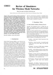
In our model, data received or produced by a peer are always processed by a software layer implementing the services of the protocol of the P2P client. Since each peer needs a bootstrap rendezvous, in order to become a part of a P2P network it will have a single logical SOCKET of communication with the rendezvous, which will record it in the list of peers qualified to use the P2P services. A schema of the logical-functional structure of a peer is shown in Figure 2, including its elaboration, memorization and network devices components. Starting from this level of description we have defined the architecture of a peer component in the P2P network. It is based on the devices of queue service describing the operation of its hardware and software components, wherein network messages are processed according to specific algorithms defined as service procedures at the stations. Particular server queues that will be described below are recognizable in Figure 10. For sake of synthesis, we will use identifiers of variables and procedures that have been defined after modelling individual devices in the programming phase. In fact, we have defined in this phase a new type of data for each base component of the P2P network, containing more inner variables of the queue type, and defined service procedures activated by network messages once they reach the servers. The
TQ311C-E/206
30 IX 2008
BOP s.c., http://www.bop.com.pl
Queue-based Simulators of P2P Networks
207
Figure 3. Architecture of a P2P network peer
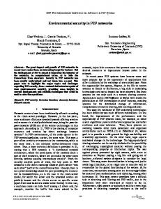
type of data peer contains the following queue type variables, with which we have defined the functioning of service stations shown in Figure 3: • USER: A source queue of local traffic generating, through the BOOT procedure, a message AdvReq type, pointing out a registration application of a peer of the P2P network, every T ARR milliseconds and sending it to the CONTROL queue. • CONTROL: This queue has a finite capacity fixed as equal to 1, used to limit the frequency of arrival messages of authentication from the local application layer of the Peer toward the protocol module, described by the PROTOCOL queue. Having crossed the filter CONTROL queue, an AdvReq message is forwarded to the PROTOCOL queue, which is the nucleus of a P2P application. The messages exceeding the fixed capacity are discarded by the system. • PROTOCOL: This station foresees an algorithm of FIFO scheduling and manages messages both getting in, Download, and going out, Upload, with two different service procedures, PR IN and PR OUT. The PR OUT procedure defines the management algorithm of messages going out from a Peer to the P2P network. These messages may be only of the following types: AdvReq, viz. an application of registration at a rendezvous, FileReq, viz. dispatch of a file application toward a network peer, or FileRes, viz. file dispatch to an applicant peer. If a message is of the AdvReq type, it is temporarily copied through the execution of the COPYBAKM procedure in the CACHE queue; otherwise it is forwarded in the Upload form without further processing toward the SOCKET queue. The PR IN procedure processes messages coming from the network; if the received message has the DESTID and DGID fields respectively corresponding to the UUID and
TQ311C-E/207
30 IX 2008
BOP s.c., http://www.bop.com.pl
208
L. Pasini and S. Feliziani
GROUPID of the receiving peer, the following three types of situations may be
the case: 1. if the message is of the ADVACK type, viz. a confirmation of effective registration from a rendezvous, the peer performs the DATA procedure that produces messages of an application file, FileReq, toward other peers and eliminates the last previously stored AdvReq message from the CACHE; 2. if the message is of the FileReq type, pointing out an application of a file from another remote peer, the peer sends a FileRes-type message toward the applicant peer through the SENDFILE procedure; 3. if the message is of the FileRes type, pointing out a message containing a resource previously requested by another remote peer, the peer forwards it to its storage device represented by the HD queue. • CACHE: Buffer memory for temporary memorization of copies of messages sent by the CONTROL queue of the network waiting for their confirmation of receipt. Failing such confirmation, after a Time Out service time, the message is re-inserted in the CONTROL queue to be re-broadcasted in the network. • HD: Messages of the FileRes type received through the network by a remote peer are introduced into this queue. The messages are sent to the HD queue, which is the Peer’s storage device, from the CONTROL queue. The received messages are stored in HD using the FSTORE variable of state. • SOCKET: This queue represents the primitive of data communication, of transport layer, between the client process executed on the peer and any other remote process of the system. Upload messages are sent, at proportional speed to the UP R band in exit, toward the queue assigned to the variable queue NETWORK pointer in the definition phase of connections among the P2P network’s devices. Symmetrically, Download messages are transferred at proportional speed to the DOWN R entrance band in the PROTOCOL queue, representing the software layer of the P2P client. The new object-type peer of the library implemented in the Qnap2.V9 programming language is stated below. /DECLARE/ OBJECT PEER (UUID, GROUPID); INTEGER UUID; INTEGER GROUPID; INTEGER IDRV; REAL T ARR; INTEGER TIME OUT; REAL CPURATE, HDRATE; REAL UP R, DOWN R; REAL FSTORE; QUEUE USER, PROTOCOL, CONTROL; QUEUE SOCKET; QUEUE CACHE, HD; REF QUEUE NETWORK; END;
A peer is univocally identified by the couple of integer numbers, UUID, GROUPID, inserted as formal parameters of the object’s builder. In addition to the
TQ311C-E/208
30 IX 2008
BOP s.c., http://www.bop.com.pl
Queue-based Simulators of P2P Networks
209
previously described queue type variables, the following variables of a new object-type peer must be defined while generating the object’s realization. When assigning values to these variables, time intervals are expressed in milliseconds (ms): • • • • • • • •
IDRV: identifying the rendezvous to which a peer is connected in the network, T ARR: generating the time of authentication messages towards the rendezvous, TIME OUT: the time of persistence of a message in the inner CACHE memory, CPURATE: the frequency of the inner processor, expressed in bits/ms, HDRATE: the frequency of the inner hard disk, expressed in bits/ms, UP R: bandwidth in upload, expressed in bits/ms, DOWN R: bandwidth in download, expressed in bits/ms, FSTORE: counter of the total number of bits accumulated by a peer during the
simulation. The template stations are a coding mechanism, available in QNAP2, enabling description through a single command /STATION/ of the procedures to serve and direct the use of a given queue for all realizations of a peer object. For example, let us consider the definition code of the rising USER queue of any peer of the network given below. In the execution phase of the simulation, the operations of stations of different realizations of a given type of object are differentiated by their values of parameters specific for the type of object. These values are assigned in the model initialization phase, after the library code has been compiled. /STATION/ NAME = *PEER.USER; TYPE = SOURCE; SERVICE = BEGIN EXP (T ARR); BOOT (UUID, GROUPID, IDRV); TRANSIT (CONTROL, UPLOAD); END; ...
Further examples could be the definition codes of template stations related to the CONTROL and PROTOCOL queues of a peer object. /STATION/ NAME = *PEER.CONTROL; CAPACITY = 1; REJECT = TRANSIT (OUT); SERVICE = TRANSIT (PROTOCOL, UPLOAD); /STATION/ NAME = *PEER.PROTOCOL; SCHED = FIFO; SERVICE (UPLOAD) = PR OUT (CPURATE); SERVICE (DOWNLOAD) = PR IN (CPURATE, UUID, GROUPID); ...
Definition codes of stations built on other queues of the peer object and of inner service procedures have been omitted due to the spatial restrictions of this paper.
2.2. The rendezvous object Functional characterization of a rendezvous object of a P2P network basically consists in the execution of two activities:
TQ311C-E/209
30 IX 2008
BOP s.c., http://www.bop.com.pl
210
L. Pasini and S. Feliziani
1. peer registration and 2. routing management of messages in the network. We have assumed in our modelling that every peer is directly connected to a rendezvous during the simulation interval. A rendezvous can be connected to one or more other rendezvous, thus connecting more heterogeneous networks. The implemented software layer of a rendezvous has to manage more simultaneous connections, each individuated by a socket device. Therefore, the role of a rendezvous in the P2P network implementation phase is assigned to computers equipped with processors of clock frequency greater than 1.8GHz and RAM memory capacity greater than 256MBs.
Figure 4. Logical-functional structure of a rendezvous
A schema of the logical-functional structure of a rendezvous object is shown in Figure 4. Every rendezvous has UUID identification that univocally countersigns it in the P2P network. The software layer of this object has a management module for peers asking to be connected to the network. The module memorizes, in a PTable chart, as many arrays of the [PeerID, PeerGID, LinkID] type as there are peers that have sent a valid registration application. The architecture of a rendezvous object (marked RV) as a model of queues’ networks is shown in Figure 5. The following single server queue service devices are discernible in the schema illustrating the RV object’s architecture, each of them having complex inner service procedures: • PROTOCOL: This station has a FIFO scheduling algorithm subjected to levels of priority with pre-emptying. It manages messages coming in, Download, and those going out, Upload, using two separate service procedures, respectively RVP DOWN and RVP UP. The RVP UP procedure performs an elaboration time depending on the size of the message and forwards it to the SOCKET queue in the Upload class. The RVP DOWN procedure performs an elaboration
TQ311C-E/210
30 IX 2008
BOP s.c., http://www.bop.com.pl
Queue-based Simulators of P2P Networks
211
Figure 5. Architecture of a rendezvous object
time depending on the size of the message and checks whether the message corresponds to the registration application sent by a peer to the rendezvous: 1. if it does, viz. if the message’s TYP field equals AdvReq, the applicant peer’s registration is performed through the REG PEER procedure. A message of the ADVACK type is sent to the CONTROL queue in the Upload class through the SADVACK procedure. Such messages have a low priority level, set at 0, and are used to notify the sending peer of effective registration; 2. otherwise, the message is re-inserted in the CONTROL queue of the Upload class with a high priority level. In this case, the message corresponds either to a request from a file to be forwarded on the P2P network in a broadcasted way or to a reply to be forwarded in a unicast way. • SOCKET: This station has a FIFO scheduling algorithm and manages messages coming in from the network, Download, and those going out toward the network, Upload, with two different procedures, respectively RVSIN and RVSOUT. The RVSIN procedure processes messages received by the network. It performs the physical receipt of messages with speed proportional to the receiving band and forwards them to the management application, represented by the PROTOCOL queue, with the Download class. The RVSOUT procedure performs the physical transmission of messages and checks their type. If a message is a generic application of the FileReq or AdvReq type, the UUID of the current RV is inserted in the last position of the message’s TRACERT chart. In this way, the necessary information on the reply path in the network is memorized in the request phase. If the message is directly destined to a peer connected and recorded in the PTable of the current RV, the message is made to transit the link corresponding to such a peer. Failing this, the dispatch algorithm is executed: 1. if the message is of the FileReq type, the current RV satisfies the specifications of the Reverse Path Forwarding algorithm, forwarding copies of the received message only to connected rendezvous other than
TQ311C-E/211
30 IX 2008
BOP s.c., http://www.bop.com.pl
212
L. Pasini and S. Feliziani
the one from which the message has come from. The links connected to the current RV, which enable forwarding messages, are collected through the CANSEND function, which individualizes all links toward the network’s rendezvous objects; 2. if the message is of the FileRes type, the link will be determined in the FORWARD procedure, scrolling the entries backwards in the message’s TRACERT chart compiled by the crossed RV in the phase of request transmission. The LinkFD device shown in Figure 5 represent the channels of communication of a rendezvous with the rest of a P2P network, realizations of a new type of object of the library described in the following sub-section. A procedure performs the connection between a rendezvous and its associated LinkFD when the P2P network is created. This procedure performs suitable assignment of values to queue pointer variables present for this purpose as inner variables in both types of objects. A P2P network’s rendezvous is implemented through an object called RV, applied with two formal parameters, UUID and N LINKS. These parameters respectively represent the rendezvous’ ID in the network and the number of links it is connected to. The object’s definition code is given below. /DECLARE/ OBJECT RV (UUID, N LINKS); INTEGER UUID; INTEGER N LINKS; REAL CPURATE; REAL UPR, DOWNR; QUEUE PROTOCOL; QUEUE SOCKET; INTEGER ID LINKS (N LINKS); REF QUEUE LINK IO (N LINKS); INTEGER PTABLE (MAXPEERS, 3); INTEGER PPOINTER; END;
The definition of the type of object includes the ability of computing, individuated by the CPURATE variable, and the networking abilities, individuated by the UPR and DOWNR parameters and measured in bit/ms. These parameters are characteristic of the RV structure’s host. The definition also contains two charts: • the PTable chart, a peer registration chart shown in picture 4, and • the links chart, implemented by using the integer arrays ID LINKS and pointer queue, LINK IO. The two arrays have the same length and ID LINKS(n) supplies the P2P network ID of the LinkFD object which the pointer LINK IO(n) queue points to. The definition code of template stations related to the inner queues of this type of objects is given below. Again, the service procedures’ code and the functions it recalls have been omitted due to our spatial restrictions. /STATION/ NAME = *RV.SOCKET; SCHED = FIFO; SERVICE (UPLOAD) =
TQ311C-E/212
30 IX 2008
BOP s.c., http://www.bop.com.pl
Queue-based Simulators of P2P Networks
213
RVSOUT (UUID, SIZE, UPR, N LINKS, ID LINKS, PTABLE, PPOINTER); SERVICE (DOWNLOAD) = RVSIN (SIZE, DOWNR); ... /STATION/ NAME = *RV.PROTOCOL; SCHED = PRIOR, PREEMPT; SERVICE (UPLOAD) = RVP UP (CPURATE); SERVICE (DOWNLOAD) = RVP DOWN (UUID, CPURATE, PTABLE, PPOINTER);
2.3. The LinkFD object This object represents the physical channel of message communication among peer type or rendezvous type terminals of a P2P network. According to the technology used, it may be wired or wireless and according to the protocol of level of data link, the transmission channel can be considered less or more reliable in the two directions of transit. This type of object represents full-duplex transmission channels of a P2P network. Evaluating the performance and reliability of a P2P system technology used, both at a physical and data link level, it is possible to see how, upon changing these technologies and transmission protocols at the data link level, the whole system is subject to remarkable variations in its performance indices. In our model, illustrated in Figure 6, a link is an object containing two channels transmitting in opposite directions, implementing a flow of full-duplex messages.
Figure 6. Logical-functional structure of a link
The new type of LinkFD objects introduced in the library represents a prototype of a P2P network link. The architecture of this object is shown in Figure 7. The LinkFD object type has two inner variables of queue type representing the two half-duplex connections of the communication channel between terminals. The two CHANNEL1 and CHANNEL2 queues of a LinkFD each implement unidirectional connections and act as converters of user classes from the Upload sender side to the Download recipient side. As the two inner queues are of the infinite server type, they are centres of delay managing the flows of data calling a specific procedure, STREAM. The definition code of the LinkFD object type is as follows. /DECLARE/ OBJECT LINKFD (ID); INTEGER ID; INTEGER LOSTMSG; REAL LOSTSIZE;
TQ311C-E/213
30 IX 2008
BOP s.c., http://www.bop.com.pl
214
L. Pasini and S. Feliziani
Figure 7. Architecture of LinkFD REAL T, P ERR; QUEUE CHANNEL1; QUEUE CHANNEL2; REF QUEUE END1, END2; END;
Any realization of a LinkFD object, and thus any link of a P2P network, has an integer ID and a bandwidth individuated by the inner T variable, expressed in bit/ms. Two additional inner variables have been defined for monitoring the loss of messages during transmission through the channel. The integer LOSTMSG variable memorizes the total number of messages lost during the simulation of a P2P network’s operation, while the real LOSTSIZE value states the amount of bits corresponding to such losses. The probability that a link of a P2P network looses a message is expressed by an inner variable called P ERR. The definition code of template stations built on two queues inside the LinkFD object is given below. /STATION/ NAME = *LINKFD.CHANNEL1; TYPE = INFINITE; SERVICE = STREAM (P ERR, T, ID, LOSTMSG, LOSTSIZE); TRANSIT = END1, DOWNLOAD; /STATION/ NAME = *LINKFD.CHANNEL2; TYPE = INFINITE; SERVICE = STREAM (P ERR, T, ID, LOSTMSG, LOSTSIZE); TRANSIT = END2, DOWNLOAD;
The STREAM procedure simulates the behaviour of a physical network: when there is a probabilistic event determined by the DRAW system function, a message is discarded and such a loss is added to the LOSTMSG and LOSTSIZE state variables. Besides, the STREAM procedure increases the POINTER field of the FileReq or AdvReq messages of request and memorizes the LinkFD’s ID in a new entry of the message’s TRACERT chart.
2.4. The message object Messages are structured in fields and contain specific payloads according to the information memorized in the different heading fields. These values characterize both the message and the actions that must be carried out on it by the various devices of a P2P network.
TQ311C-E/214
30 IX 2008
BOP s.c., http://www.bop.com.pl
Queue-based Simulators of P2P Networks
215
Figure 8. Logical-functional structure of a message
The logical-functional structure of a generic message transmitted via a P2P network is shown in Figure 8. A description of the fields appearing in the message’s structure follows: • • • • •
SENDID: the integer ID of the sender peer, SGID: the integer ID of the group to which the sender peer belongs, DESTID: the integer ID of the recipient peer, DGID: the integer ID of the group to which the recipient peer belongs, TYP: a string characterizing the message type, with four values allowed,
AdvReq, AdvAck, FileReq and FileRes, • SIZE: the message size, expressed in bits, • COUNT: a counter of the number of hops effected by the message on its path to the destination, • POINTER: a pointer to a record of the TRACERT chart, • TRACERT: the chart containing information related to the path followed by a message to its destination; every record of the chart is composed of a (IDLink, IDRV) couple, IDLink being the ID of a crossed Link and IDRV – the ID of the rendezvous to which the link, IDLink, introduces messages. The message definition code is given below. It has been implemented by extending the ownerships of the CUSTOMER type object, i.e. a type of default object in the Qnap2.V9 programming language. CUSTOMER states the generic user of a network of service devices. A message has been defined as a subtype of the CUSTOMER object type. The inner variables added to its definition, given below, correspond to the fields shown in Figure 8. /DECLARE/ CUSTOMER OBJECT MESSAGE; INTEGER SENDID, DESTID, SGID, DGID; STRING TYP; REAL SIZE; INTEGER COUNT; INTEGER POINTER; INTEGER TRACERT (MAX HOPS, 2); END;
TQ311C-E/215
30 IX 2008
BOP s.c., http://www.bop.com.pl
216
L. Pasini and S. Feliziani
3. P2P protocol implementation In this section, we describe the way in which the layer of the network protocol managing communication sessions among components of the P2P network defined above has been implemented. The P2P network protocol supplies procedures to every peer to be connected to a group of peers, as well as to require or supply resources to another peer of the network. In the following sub-sections, we describe the procedures of the P2P protocol that we have implemented to construct simulators of P2P networks. In this context, particular operational phases of the protocol procedures are realized through execution of the service procedures of queues in the P2P network’s components. The service procedures in the network devices are performed by messages activating the service algorithms. The simulation of every protocol phase corresponds to the execution of a specific service procedure for a given type of user in a queue in a P2P network component.
3.1. The bootstrap procedure This procedure represents the way in which a peer is recorded at a rendezvous of a P2P network. It reproduces the first network access phase of a peer. In this phase, the peer sends a registration application to the rendezvous it wants to connect to. The application is sent cyclically until it receives a notice of positive registration by the rendezvous. Upon receiving a registration application from the Peer, the rendezvous memorizes the [PeerID, PeerGID, LinkID] triplet present in the structure of the message, in its PTable chart. When the Peer has been recorded, it can use the rendezvous’ services to send or receive resources through the sharing procedures of the P2P network resources. The logical-functional schema of the procedure is shown in Figure 9. The scheme refers to the structure of a generic P2P network. The phases of the boostrap procedure have been numbered sequentially in Figure 9 and are described below:
Figure 9. The bootstrap procedure: registration of a peer at a rendezvous
1. peer (2, 3) cyclically sends a registration application to rendezvous 1 (until confirmation of positive registration by rendezvous 1);
TQ311C-E/216
30 IX 2008
BOP s.c., http://www.bop.com.pl
Queue-based Simulators of P2P Networks
217
2. rendezvous 1 memorizes the [PeerID, PeerGID, LinkID] triplet in its PTable chart; 3. rendezvous 1 produces a confirmation message and sends it to peer (2, 3), which has been recorded in the P2P network; 4. peer (2, 3) notifies the receipt of the registration confirmation and starts sharing its resources.
3.2. The file request procedure This procedure describes the way a P2P network peer produces an application for a file available as a shared resource c/o another peer of the network. The peer producing the request forwards it to its rendezvous, which handles it to deliver the request to the recipient peer. The mechanism of request transmission among rendezvous follows routing specifications. The rendezvous transmit the incoming messages addressed to the network to all the links connected to them other than the Link the message has come from. Thus, every rendezvous of the network will receive at least a copy of the message sent by the applicant peer. The rendezvous directly connected to the recipient peer of the request message does not forward it in a broadcast way to the network but delivers it to the destination peer. A schema of the file request procedure’s operation is shown in Figure 10, where execution phases are numbered according to the particular example of network configuration:
Figure 10. Sequence of phases of a the file request procedure
1. peer (2, 3) produces a request for a file that is an online resource shared by peer (1, 2) and forwards it to its rendezvous 1; 2. the rendezvous broadcasts the request to the other rendezvous of the P2P network. Every rendezvous memorizes the local information of the path in the TRACERT of the message (IDs of the link of origin and the rendezvous). This information is used by the response message transmitted in a unicast way through the P2P network; 3. rendezvous 2, which holds the registration of peer (1, 2), forwards the request to peer (1, 2).
TQ311C-E/217
30 IX 2008
BOP s.c., http://www.bop.com.pl
218
L. Pasini and S. Feliziani
When a message requesting a file crosses a rendezvous of the P2P network, it transits – in the exit phase – the SOCKET queue of the rendezvous where it performs the RVSOUT service procedure. These mechanisms have already been described in Section 2.2 above and will be recalled here only briefly. The structure of a message has been described in Section 2.3 above. Each message contains a chart, called TRACERT and formed by two columns: IDLink and IDRV. When a LinkFD transmits a file request message through a P2P network, the service algorithm of the CHANNEL queue increases the content of the POINTER field of the message pointing to a new empty record of the TRACERT chart. This service algorithm memorizes the ID of the entry Link to the rendezvous in the IDLink field. When the message is transmitted going out from the SOCKET queue of the rendezvous, the RVSOUT procedure memorizes the UUID of the rendezvous in the second IDRV field of the record pointed by the POINTER variable. When the file request message reaches its destination, it performs the service procedures in the inner queues of the receiving peer. These procedures modify the TYP field of the message converting it into a response message transmitted through the network toward the peer that had sent the request message. The TRACERT chart of the response message is not modified by the service procedures and contains the information memorized by the message on its path through the network as a file request. Thus, the peer, i.e. the recipient of the file request message, produces a response transmitted in a unicast way by a rendezvous of the P2P network. In fact, every rendezvous that receives a response message, uses the information contained in its TRACERT chart to forward it in a unicast way backward along its path in the file request phase.
3.3. The file response procedure This procedure describes the way of transmission through a P2P network of a response message containing a copy of the file requested by a remote peer. The receipt and transmission mechanism of the response message through the network’s rendezvous is implemented by the service algorithms performed by the message when it enters the service devices in the network’s components. In particular, a response message crossing a network rendezvous is inserted in the SOCKET queue, where it performs the RVSOUT service procedure. This procedure decreases by one the value of the POINTER field of the message, accesses the ID of the Link where the message has to be sent and reads the ID of the network component the Link is connected to. Thus, the TRACERT chart of the message, where the succession of peers and rendezvous crossed in the file request phase has been memorized, is used for determining the inverse path of the response message along the network. When a peer of a P2P network receives a response message, it memorizes the content of the message payload field in its own HD local memorization device. A schema of the dispatch and transmission phases of response along a P2P network following a file request by a remote peer is shown in Figure 11, phases related to the file request shown in Figure 10 have been numbered accordingly: 1. peer (1, 2) answers to the request of peer (2, 3) and sends it to rendezvous 2; 2. rendezvous forward the response message in a unicast way using the TRACERT chart of the message;
TQ311C-E/218
30 IX 2008
BOP s.c., http://www.bop.com.pl
Queue-based Simulators of P2P Networks
219
Figure 11. Sequence of phases of the file response procedure
3. peer (2, 3) memorizes the message in its own HD local memorization device.
3.4. Performances evaluation In the implementation of the protocol data link layer a probability of signal loss is foreseen, which can be a meaningless event. Therefore, during the bootstrap procedure a peer sends a registration request to its rendezvous in a cyclical way, in order to guarantee that the peer’s registration on the P2P network is effected with acceptable response time. In order to avoid this traffic interfering with requests’ and responses’ transmission among the network’s peers, registration messages are managed by the rendezvous with inferior priority, while the request and response ones are processed by the protocol form with greater priority. Besides, in order to avoid redundant cycles of message transmission among the network’s rendezvous in the execution of file request procedures, the value of the COUNT field of a message, which is initially zero, is increased by one by the processing rendezvous. Thus, when the COUNT field value of a request message reaches the maximum acceptable value, being a function of the network’s complexity, the message is discarded. The construction of a P2P network simulator enables the simulation of the functioning of a generic P2P network for a determined interval of time. Upon starting the simulation, the network is physically shaped with regard to the sub-network formed from the rendezvous and from the connection channels among them. Both the peers present in the P2P network and the structure of the groups are defined at this point, but the peers’ registration procedures have not been performed yet. The traffic of network data at the very start moment of the simulation is nil and the inner service devices are empty. In this context, the execution of the simulation procedure initiates the generation of peer registration applications in the rendezvous and the generation of messages sent through the network according to the protocol procedures presented above. In our case it is a simulation procedure of discrete events, which produces events describing transmission of messages through the network’s devices. The events produced in a simulation are ordered according to the moment of their
TQ311C-E/219
30 IX 2008
BOP s.c., http://www.bop.com.pl
220
L. Pasini and S. Feliziani
foreseen execution. The simulation time is measured in milliseconds. The simulator resolves events produced during the simulation sequentially, skipping from an event in the execution moment to the following event, irrespective of the time interval separating the two consecutive moments. The time interval is taken into account in the simulation measures. The simulation of a P2P network has enabled us observation at pre-set time intervals of the course of messages’ traffic in the network and the state of queues in the various network devices. In particular, we have monitored the course of values of the following variables describing the state of the traffic in a P2P network: • the number of memorized bytes in the HD devices of each peer, • the mean response time experienced by messages in the PROTOCOL and SOCKET queues of each peer, • the mean response time experienced by messages in the PROTOCOL and SOCKET queues of each peer rendezvous, • the number of messages and bytes lost in the CHANNEL1 and CHANNEL2 queues of each link, and • the mean service time in the CHANNEL1 and CHANNEL2 queues of each link.
4. P2P network simulators The generation of a P2P network simulator is obtained automatically through the execution of the BuildMod procedure that defined in the Qnap2.V9 programming language, an approach introduced in our earlier publications (see bibliography). It consists in performing the followings steps enabling automatic management of generating simulators related to different P2P network models: 1. defining filling and compiling of the library files of the system’s components: these library files contain definitions of the types of objects used in modelling the system and all the internal procedures connected to the description of their operation; 2. defining filling and compiling of the library files of the procedure of simulator generation: these files contain definitions of the BuildMod procedure and definitions of the functions and the accessory procedures; they initially contain the call to a procedure, in the programming context, performing the inclusion of the first library file. Once the two library files have been filled and compiled, a simulator of a particular P2P network is generated by the network description file Model.dat, executing a program file containing the calls of the following procedures: • an internal procedure for the inclusion of the two library files, • an internal procedure for setting the reading operations being executed on the Model.dat file, and • the BuildMod procedure. BuildMod produces a simulator by performing the reading functions on the Model.dat file. Model.dat is a text file containing the descriptive data of all the components of the P2P network. Therefore, a Model.dat file describing the structure of the network corresponds to each P2P network model. The file’s first record contains
TQ311C-E/220
30 IX 2008
BOP s.c., http://www.bop.com.pl
Queue-based Simulators of P2P Networks
221
fields for the network’s number of peers, rendezvous and links. These values are read by the procedure and assigned to the variable checking the limit of generation cycles of various devices. The characteristic parameters of peers are organized in records in a default order and are read sequentially by the BuildMod procedure. The BuildMod procedure reads as many records from the Model.dat file in a peer’s generation cycle as there are network peers to be created. Therefore, the structure of data in the Model.dat file depends on the structure of the definition code of the BuildMod procedure, particularly on the execution sequence of the operations of device generation and reading the internal parameter values. The BuildMod procedure is structured in specific code sections for the execution of the following actions: • generation of the single devices present in the P2P network: these devices are produced as instances of the types of objects defined in the first library file, the value of their inner characteristic parameters being read by the Model.dat file and assigned in the same execution time; • realization of connections among the produced individual components of the P2P network. These actions are realized by executing instructions in the procedure, organized in the adjoining code sections. During execution of every code section the procedure sequentially reads a number of records determined by the value of the global reference variable. The code sections in the BuildMod procedure generating a P2P network simulator with their functional characterization are as follows: 1. 2. 3. 4. 5. 6.
definition and initialization of global variables, creation and initialization of peer objects, creation and initialization of rendezvous objects, creation and initialization of LinkFD objects, realization of peer-rendezvous connections and realization of rendezvous-rendezvous connections.
4.1. Exemplary structures of P2P networks In this section, we describe three types of P2P networks of basic structure shown in Figure 12. In the following paragraphs, we describe the construction of simulators related to three network configurations, differing in the technology used for the realization of the interconnection network between the peers and the rendezvous [4], being: 1. Fast Ethernet, with connections’ throughput of 100Mbps, 2. Wireless, with standard IEEE 802.11 g and connections’ throughput of 54Mbps, and 3. ADSL2+, with standard ITU G.992.5 M and connections’ throughput of 3.5Mbps. From the structural point of view, these are three different P2P networks; we shall now build a simulator for each of them based on the objects library and protocol procedures defined in the previous paragraphs. We keep the network’s topology and capacity for peer and the rendezvous processing constant in the three study cases. Besides, we have assumed that the
TQ311C-E/221
30 IX 2008
BOP s.c., http://www.bop.com.pl
222
L. Pasini and S. Feliziani
Figure 12. Structure of the reference P2P network
characteristics of connections among the P2P network’s rendezvous are fixed in the structure of the reference P2P network. These have a transmission speed of 10Mbps and a probability of signal loss of 10−9. The simulation results, given below, illustrate the performance of the P2P network according to the technology selected to realize the interconnection networks between the peers and the rendezvous. As can be seen in Figure 12, the reference P2P network has the following basic characteristics: 1. there are 10 peers in the network, divided in two groups, 1 and 2; 2. there are 5 rendezvous in the network; 3. there are 15 LinkFDs, of which 10 connect a peer with the respective rendezvous in the network, while the other 5 form, together with the rendezvous, the main sub-network of the reference P2P network. The 5 links of the main sub-network of the P2P network have a transmission capacity of 10Mbps.
4.2. Fast Ethernet P2P network In this case we hypothesize that the reference P2P network shown in Figure 12 is characterized by the presence of local peer interconnection networks of the LAN Fast Ethernet type, where the throughput of connections is equal to 100Mbps. The Model.dat file of this P2P network is given below, including the six sections into which the network description data are divided. The data in these sections are read sequentially by the BuildMod procedure during the execution of the corresponding procedure’s code section. Each data section begins with a comment pointing out the nature of data contained in the section. There are also other comments in a data section containing a description of values contained in the fields corresponding to the underlying records up to the following comment or at the end of the section. In our programming context, the symbol of comment is highlighted by the & character. When the BuildMod procedure reads this character in execution, it skips it to read the following record.
TQ311C-E/222
30 IX 2008
BOP s.c., http://www.bop.com.pl
223
Queue-based Simulators of P2P Networks
In section 4 of the Model.dat file, the rate parameter, measuring the channels’ transmission capacity, assumes the value of 100Mbps for the peer interconnection channels, characteristic of this type of P2P networks. The channels are identified by an ID value varying from 1 to 10, as shown in Figure 12. The value, effectively brought back in the rate field of links, is expressed in the simulation time unit, viz. the millisecond (ms), and equals 100 000bpms. The rendezvous interconnection channels (see Figure 12) have a fixed throughput of 10Mbps. The Model.dat file producing the P2P network simulator shown in Figure 12 with a LAN Fast Ethernet peer interconnection network is as follows: Section 1 & GLOBAL VARIABLES & Number of peers Number of rendezvous 10 5 & ADVREQ Size ADVACK Size FILEREQ Size 1024.0 1024.0 8192.0 & Max UUID Max GROUPID Max HOPS 5 2 10; & SIMULATION & TMAX PERIOD 500000.0 50000.0;
Number of links 15; FILERES Size 262144.0;
Section 2 & PEERS & UUID GROUPID T ARR 1 1 5000.0 2 1 4980.0 3 1 5000.0 4 1 2900.0 5 1 6000.0 1 2 5000.0 2 2 4800.0 3 2 5000.0 4 2 5000.0 5 2 3000.0
TIMEOUT 5911 3934 4955 5913 3934 2946 3951 4942 4927 5921
CPURATE 64000000.0 96000000.0 16000000.0 32000000.0 16000000.0 64000000.0 64000000.0 16000000.0 96000000.0 32000000.0
HDRATE 80000.0 100000.0 5000.0 80000.0 56000.0 80000.0 80000.0 8000.0 100000.0 10000.0
UP Rate 98000.0 100000.0 100000.0 98000.0 100000.0 97000.0 100000.0 98000.0 100000.0 99000.0
DOWN Rate 100000.0 99000.0 100000.0 100000.0 100000.0 100000.0 98000.0 99000.0 100000.0 100000.0
Section 3 & RENDEZVOUS & UUID NLINKS 100 5 101 3 102 5 103 5 104 2
CPU RATE 64000000.0 96000000.0 64000000.0 96000000.0 64000000.0
UP Rate 98000.0 100000.0 100000.0 98000.0 100000.0
DOWN Rate 100000.0; 98000.0; 100000.0; 98000.0; 100000.0;
Section 4 & Links & ID 1 2 3 4 5
Rate 100000.0 100000.0 100000.0 100000.0 100000.0
P ERR 1E-09; 1E-09; 1E-09; 1E-09; 1E-09;
TQ311C-E/223
30 IX 2008
BOP s.c., http://www.bop.com.pl
IDRV 100; 101; 103; 102; 104; 102; 101; 100; 102; 103;
224
L. Pasini and S. Feliziani 6 7 8 9 10 11 12 13 14 15
100000.0 100000.0 100000.0 100000.0 100000.0 10000.0 10000.0 10000.0 10000.0 10000.0
1E-09; 1E-09; 1E-09; 1E-09; 1E-09; 1E-09; 1E-09; 1E-09; 1E-09; 1E-09;
& Peer-RV links & LINK ID UUID 1 1 2 3 3 3 4 5 5 5 6 4 7 1 8 4 9 2 10 2
GROUPID 1; 2; 1; 2; 1; 2; 2; 1; 2; 1;
Section 5
Section 6 & RV-RV links & LINK ID RV1 11 100 12 100 13 100 14 102 15 103
RV2 101; 102; 103; 103; 104;
4.3. Wireless P2P network In this case we hypothesize that the reference P2P network shown in Figure 12 is characterized by the presence of local peer interconnection networks of the Wireless type of the IEEE 802.11 g standard, where the connections’ throughput equals 54Mbps. In the Model.dat file describing this type of P2P networks, the rate parameter data of peer interconnection channels in the file’s section have been modified. The new value, expressed using the simulation time unit, is 54 000bpms. We have also modified, according to the new network structure, the values of UP Rate and DOWN Rate parameters of the peer and the rendezvous, respectively representing the bandwidths in upload and download of these devices. These data are expressed in milliseconds as well and have value ranging from 52 000bpms to 54000bpms. The sections of the Model.dat file related to this P2P network configuration affected by the changes are given below (we have omitted sections 1, 5 and 6):
TQ311C-E/224
30 IX 2008
BOP s.c., http://www.bop.com.pl
225
Queue-based Simulators of P2P Networks ...
Section 2 & PEERS & UUID GROUPID T ARR 1 1 5000.0 2 1 4980.0 3 1 5000.0 4 1 2900.0 5 1 6000.0 1 2 5000.0 2 2 4800.0 3 2 5000.0 4 2 5000.0 5 2 3000.0
TIMEOUT 5911 3934 4955 5913 3934 2946 3951 4942 4927 5921
CPURATE 64000000.0 96000000.0 16000000.0 32000000.0 16000000.0 64000000.0 64000000.0 16000000.0 96000000.0 32000000.0
HDRATE 80000.0 100000.0 5000.0 80000.0 56000.0 80000.0 80000.0 8000.0 100000.0 10000.0
UP Rate 54000.0 54000.0 54000.0 52000.0 54000.0 54000.0 53000.0 54000.0 52000.0 54000.0
DOWN Rate 53000.0 52000.0 54000.0 54000.0 53000.0 54000.0 52000.0 54000.0 54000.0 54000.0
IDRV 100; 101; 103; 102; 104; 102; 101; 100; 102; 103;
Section 3 & RENDEZVOUS & UUID NLINKS 100 5 101 3 102 5 103 5 104 2
CPU RATE 64000000.0 96000000.0 64000000.0 96000000.0 64000000.0
UP Rate 54000.0 54000.0 53000.0 54000.0 53000.0
DOWN Rate 53000.0; 54000.0; 53000.0; 54000.0; 53000.0;
Section 4 & Links & ID 1 2 3 4 5 6 7 8 9 10 11 12 13 14 15 ...
Rate 54000.0 54000.0 54000.0 54000.0 54000.0 54000.0 54000.0 54000.0 54000.0 54000.0 10000.0 10000.0 10000.0 10000.0 10000.0
P ERR 1.E-07; 1.E-07; 1.E-07; 1.E-07; 1.E-07; 1.E-07; 1.E-07; 1.E-07; 1.E-07; 1.E-07; 1.E-09; 1.E-09; 1.E-09; 1.E-09; 1.E-09;
4.4. ADSL2+ P2P Network In this case we hypothesize that the reference P2P network defined in Figure 12 is characterized by the presence of local peer interconnection networks of the ADSL2+ type and the ITU (International Telecommunication Union) G.992.5 Annex M standard, where the upstream connections throughput reaches the value of 3.5Mbps. The simulation time is again expressed in milliseconds, while the rate parameter of the networks’ peer interconnection links, found in section 4 of the Model.dat file, assumed the value of 3500bpms. The parameters specifying the upload and download bandwidth of the P2P network’s peer devices have been adapted to the new network structure.
TQ311C-E/225
30 IX 2008
BOP s.c., http://www.bop.com.pl
226
L. Pasini and S. Feliziani
The rendezvous of this P2P network have values of the UP Rate and DOWN Rate parameters equal to 10Mbps, in order not to go below the transimission rate of the main sub-network. The Model.dat file producing the P2P network simulator shown in Figure 12 with peer interconnection network of the ADSL2+ type is given below. Again, we have omitted sections 1, 5 and 6 of the file, coinciding with those of the Model.dat file described for the first network type: ...
Section 2 & PEERS & UUID GROUPID T ARR 1 1 5000.0 2 1 4980.0 3 1 5000.0 4 1 2900.0 5 1 6000.0 1 2 5000.0 2 2 4800.0 3 2 5000.0 4 2 5000.0 5 2 3000.0
TIMEOUT 5911 3934 4955 5913 3934 2946 3951 4942 4927 5921
CPURATE 64000000.0 96000000.0 16000000.0 32000000.0 16000000.0 64000000.0 64000000.0 16000000.0 96000000.0 32000000.0
HDRATE 80000.0 100000.0 5000.0 80000.0 56000.0 80000.0 80000.0 8000.0 100000.0 10000.0
UP Rate 3500.0 3500.0 3500.0 3500.0 3500.0 3500.0 3500.0 3500.0 3500.0 3500.0
DOWN Rate 3500.0 3500.0 3500.0 3500.0 3500.0 3500.0 3500.0 3500.0 3500.0 3500.0
Section 3 & RENDEZVOUS & UUID NLINKS 100 5 101 3 102 5 103 5 104 2
CPU RATE 64000000.0 96000000.0 64000000.0 96000000.0 64000000.0
UP Rate 10000.0 10000.0 10000.0 10000.0 10000.0
DOWN Rate 10000.0; 10000.0; 10000.0; 10000.0; 10000.0;
Section 4 & Links & ID 1 2 3 4 5 6 7 8 9 10 11 12 13 14 15
Rate 3500.0 3500.0 3500.0 3500.0 3500.0 3500.0 3500.0 3500.0 3500.0 3500.0 10000.0 10000.0 10000.0 10000.0 10000.0
P ERR 1.E-05; 1.E-05; 1.E-05; 1.E-05; 1.E-05; 1.E-05; 1.E-05; 1.E-05; 1.E-05; 1.E-05; 1.E-09; 1.E-09; 1.E-09; 1.E-09; 1.E-09;
...
TQ311C-E/226
30 IX 2008
BOP s.c., http://www.bop.com.pl
IDRV 100; 101; 103; 102; 104; 102; 101; 100; 102; 103;
Queue-based Simulators of P2P Networks
227
5. Simulation results Once the P2P network simulator has been produced, the SIMUL procedure of the Qnap2.V9 language is performed. This procedure activates the simulator to discrete event simulator of the P2P network implemented by the BuildMod procedure. The simulation’s duration is established through the value attributed to the system parameter TMAX. This value is assigned by the BuildMod procedure reading it in section 1 of the P2P network’s description file, Model.dat. The length of the simulation interval is measured in the simulation time units, in accordance with the values given to the inner parameters of the P2P network service. In our study context, the simulation time units are milliseconds. The P2P network simulations described above have concerned a temporal interval of 500 000 milliseconds. For each of the three P2P network types described in Section 4, we have generated a simulation program and simulated the functioning of the network for a time interval of 500 seconds, starting from a network state configuration where all the internal devices are empty. During the simulations’ execution, we periodically performed a test procedure on the network’s state checking the number of messages present in the service devices of the network components and calculating the mean response time. The test procedure was performed every 50 seconds. This interval was defined through the PERIOD system parameter; the 50 000 value was assigned to it by the BuildMod procedure, which had read it from section 1 of the Model.dat file. The test procedure of the P2P network was defined as a library procedure. It allowed us to follow and trace the evolution of traffic in the network at all times during the whole simulation interval. The surveys were effected periodically every 50 seconds of simulation time and measurements results were provided as graphic charts. The final charts, printed at the simulation’s end for the three P2P network models, are given below. For every model of P2P network, the results have been divided into three charts related to the following network components: 1. peer, 2. rendezvous and 3. LinkFD. Every chart contains columns with the characteristic input parameters of the various devices and the values of performance parameters measured during the simulation. The last columns of the charts related to the peers and the rendezvous contain the following values, calculated in the last test performed on the system and referring to the last period of 50 seconds of simulation: • PROTOCOL RespTime: the mean response time of the PROTOCOL queue, • SOCKET RespTime: the mean response time of the SOCKET queue, and • SOCKET ServTime: the mean service time of the SOCKET queue. The mean response time represents the average time spent by a user in the queue, including the waiting time and the effectively received service time. The difference between the mean response time and the mean service time gives the mean
TQ311C-E/227
30 IX 2008
BOP s.c., http://www.bop.com.pl
228
L. Pasini and S. Feliziani
waiting time of a user in the service device queue. The value is a measure of the level of congestion at the service device. The last column of the result charts for peers and rendezvous contains the values of the following parameter, measured globally for the whole duration of the simulation: • SOCKET ServNumb: the number of users served by the SOCKET queue. The chart related to the rendezvous is followed by a schema of the registration list of P2P network peers for every rendezvous. In the charts of the link results, the last two columns contain the following values, calculated by the last test performed on the system and referring to the last period of 50 seconds of simulation: • CHANNEL1 RespTime: the mean response time of the CHANNEL1 queue of a link and • CHANNEL2 RespTime: the mean response time of the CHANNEL2 queue of a link. In this case, response time coincides with service time since CHANNEL1 and CHANNEL2 queues of every link are modelled as service devices with infinite servers. Thus, when a user reaches the service device it immediately accesses the service phase, without queuing. These parameters measure the mean message transmission time through a link’s channels. Each simulation required a few instants of CPU time on a Personal Computer with an Intel Pentium 4 processor of 1.8GHz and 256MB RAM. In the first two cases, the simulations required memory occupation of less than 3%. In the third case, the system results congested with high accumulations of users in the internal devices and, as a consequence, the simulation process involved a higher memory occupation percentage.
5.1. Fast Ethernet P2P network The execution parameters of the simulation process of this P2P network are as follows: memory used: 410468 words of 4 bytes (2.74% of total memory); the result charts of the simulation follow; time: 0.5 · 106 ms. The response times of the peer and rendezvous devices’ PROTOCOL queues are low. The data suggest that the queues are not congested with this P2P network configuration. The SOCKET queues are interfaces of the devices with the network’s communication channels. These queues have service speeds depending on the upload and download frequencies. As far as peers are concerned, the mean service time of SOCKET queues is between 1 and 2 milliseconds, while their mean response time is between 2 and 4 milliseconds. The highest mean time value of waiting in a queue, 2.708 milliseconds, has been registered for peer (4, 1). This value has been obtained as the difference between the mean response time, RespTime, and the mean service time, ServTime. The data, especially the number of consumers served during the simulation, suggest that the devices are not congested and their mean throughput is high.
TQ311C-E/228
30 IX 2008
BOP s.c., http://www.bop.com.pl
229
Queue-based Simulators of P2P Networks Table 1. Peers UUID
GROUPID
ID
TARR
CPU Rate
HD Rate
[b/ms]
[b/ms]
Upload Rate [b/ms]
0.64 · 108 0.96 · 108 0.16 · 108 0.32 · 108 0.16 · 108 0.64 · 108 0.64 · 108 0.16 · 108 0.96 · 108 0.32 · 108
0.80 · 105 0.10 · 106 0.50 · 104 0.80 · 105 0.56 · 105 0.80 · 105 0.80 · 105 0.80 · 104 0.10 · 106 0.10 · 105
0.98 · 105 0.10 · 106 0.10 · 106 0.98 · 105 0.10 · 106 0.97 · 105 0.10 · 106 0.98 · 105 0.10 · 106 0.99 · 105
rendezvous 1 2 3 4 5 1 2 3 4 5
1 1 1 1 1 2 2 2 2 2
100 101 103 102 104 102 101 100 102 103
5000 4980 5000 2900 6000 5000 4800 5000 5000 3000
UUID
Download Rate [b/ms]
Bytes Stored
PROTOCOL
SOCKET
SOCKET
SOCKET
RespTime
RespTime
ServTime
ServNumb
0.10 · 106 0.99 · 105 0.10 · 106 0.10 · 106 0.10 · 106 0.10 · 106 0.98 · 105 0.99 · 105 0.10 · 106 0.10 · 106
0.1549 · 109 0.1214 · 109 0.1559 · 109 0.2361 · 109 0.1438 · 109 0.2512 · 109 0.1241 · 109 0.1686 · 109 0.1775 · 109 0.2230 · 109
0.2311 · 10−2 0.1487 · 10−2 0.8959 · 10−2 0.4989 · 10−2 0.9157 · 10−2 0.2699 · 10−2 0.2224 · 10−2 0.9436 · 10−2 0.1732 · 10−2 0.4994 · 10−2
2.518 2.900 2.463 4.262 2.792 2.903 2.831 2.689 2.591 2.992
1.434 1.367 1.356 1.554 1.381 1.710 1.379 1.488 1.586 1.512
15 323 25 916 17 817 19 531 26 784 17 751 24 647 16 275 14 870 18 676
1 2 3 4 5 1 2 3 4 5
Table 2. Rendezvous UUID
Links Number
100 101 102 103 104 UUID
100 101 102 103 104
CPU Rate
[b/ms] 8
5 3 5 5 2
0.64 · 10 0.96 · 108 0.64 · 108 0.96 · 108 0.64 · 108
Upload Rate [b/ms] 5
0.98 · 10 0.10 · 106 0.10 · 106 0.98 · 105 0.10 · 106
SOCKET
SOCKET
SOCKET
RespTime
ServTime
ServNumb
26.00 10.52 21.28 74.94 2.688
1.281 1.073 1.136 1.230 0.7675
190 650 132 244 183 110 181 492 105 987
Download Rate [b/ms] 6
0.10 · 10 0.98 · 105 0.10 · 106 0.98 · 105 0.10 · 106
REGISTRATIONS ([UUID, GROUPID, LINK])
rendezvous rendezvous rendezvous rendezvous rendezvous
100: 101: 102: 103: 104:
[3, [2, [1, [5, [5,
2, 2, 2, 2, 1,
2] 9] 7] 4] 5]
[1, [2, [4, [3,
TQ311C-E/229
1, 1, 2, 1,
1] 10] 6] [4, 1, 8] 3]
30 IX 2008
BOP s.c., http://www.bop.com.pl
PROTOCOL
RespTime 0.2004 · 10−2 0.1122 · 10−2 0.1802 · 10−2 0.1265 · 10−2 0.1197 · 10−2
230
L. Pasini and S. Feliziani
Table 3. Links ID
1 2 3 4 5 6 7 8 9 10 11 12 13 14 15
Rate [b/ms] 6
0.1 · 10 0.1 · 106 0.1 · 106 0.1 · 106 0.1 · 106 0.1 · 106 0.1 · 106 0.1 · 106 0.1 · 106 0.1 · 106 0.1 · 105 0.1 · 105 0.1 · 105 0.1 · 105 0.1 · 105
Loss Probability
Messages Lost
Bytes Lost
CHANNEL1
CHANNEL2
RespTime
RespTime
0.1 · 10 0.1 · 10−8 0.1 · 10−8 0.1 · 10−8 0.1 · 10−8 0.1 · 10−8 0.1 · 10−8 0.1 · 10−8 0.1 · 10−8 0.1 · 10−8 0.1 · 10−8 0.1 · 10−8 0.1 · 10−8 0.1 · 10−8 0.1 · 10−8
0 0 0 0 0 0 0 0 0 0 0 0 0 0 0
0 0 0 0 0 0 0 0 0 0 0 0 0 0 0
1.708 1.679 1.774 1.531 2.110 1.634 1.456 1.489 2.059 2.113 4.891 10.25 9.820 8.425 3.625
1.294 1.334 1.130 1.527 0.8264 1.576 1.791 1.546 0.7985 0.7494 21.37 8.032 8.877 9.623 20.35
−8
As far as the SOCKET queues of the rendezvous are concerned, the measured mean service times are about 1 millisecond, while the values of the mean response time are slightly higher in some cases. The maximum value of the mean response time, equal to 74.94ms, has been measured for rendezvous 103, characterized by the upload and download frequency of 0.98 · 105 b/ms. The data suggest that the mean number of users present in the SOCKET queue of the rendezvous is insignificant. The devices work effectively and are characterized by very high mean throughputs, as suggested by the values corresponding to the ServNumb SOCKET parameter. As far as P2P network links are concerned, the mean response times are very low on the transmission channels in the links of the fast ethernet type, characterized by very high transmission speeds. The mean response times in the channels of rendezvous interconnection links, characterized by IDs between 11 and 15, are higher. These values depend on the mean size of messages in transit through the channel and the channel’s transmission speed, given in the first column of the chart.
5.2. Wireless P2P network The execution parameters of the simulation process of this P2P network are as follows: memory used: 402181 words of 4 bytes (2.68% of total memory); the charts of simulation results follow; time: 0.5 · 106 ms. Also with this configuration of the P2P network, the PROTOCOL queues of the peer and rendezvous devices have very low mean response times with nil level of queue congestion. The SOCKET queues of the peers have a higher mean service time compared to the corresponding values of the previous network due to a lower upload and download speed. The mean response times are acceptable and the mean waiting times mean that the subsystem formed by the peers is not congested by this P2P network
TQ311C-E/230
30 IX 2008
BOP s.c., http://www.bop.com.pl
231
Queue-based Simulators of P2P Networks Table 4. Peers UUID
GROUPID
ID
TARR
CPU Rate
HD Rate
[b/ms]
[b/ms]
Upload Rate [b/ms]
0.64 · 108 0.96 · 108 0.16 · 108 0.32 · 108 0.16 · 108 0.64 · 108 0.64 · 108 0.16 · 108 0.96 · 108 0.32 · 108
0.80 · 105 0.10 · 106 0.50 · 104 0.80 · 105 0.56 · 105 0.80 · 105 0.80 · 105 0.80 · 104 0.10 · 106 0.10 · 105
0.54 · 105 0.54 · 105 0.54 · 105 0.52 · 105 0.54 · 105 0.54 · 105 0.53 · 105 0.54 · 105 0.52 · 105 0.54 · 105
rendezvous 1 2 3 4 5 1 2 3 4 5
1 1 1 1 1 2 2 2 2 2
100 101 103 102 104 102 101 100 102 103
5000 4980 5000 2900 6000 5000 4800 5000 5000 3000
UUID
Download Rate [b/ms]
Bytes Stored
PROTOCOL
SOCKET
SOCKET
SOCKET
RespTime
RespTime
ServTime
ServNumb
0.53 · 105 0.52 · 105 0.54 · 105 0.54 · 105 0.53 · 105 0.54 · 105 0.52 · 105 0.54 · 105 0.54 · 105 0.54 · 105
0.1569 · 109 0.1231 · 109 0.1642 · 109 0.2154 · 109 0.1385 · 109 0.2523 · 109 0.1261 · 109 0.1752 · 109 0.1586 · 109 0.2290 · 109
0.2320 · 10−2 0.1491 · 10−2 0.8974 · 10−2 0.4855 · 10−2 0.9138 · 10−2 0.2670 · 10−2 0.2218 · 10−2 0.9657 · 10−2 0.1683 · 10−2 0.5057 · 10−2
4.690 5.697 4.219 10.12 5.164 4.923 5.596 4.632 4.667 7.097
2.727 2.569 2.543 2.915 2.625 3.066 2.659 2.742 2.918 2.821
15 367 25 303 16 679 18 601 26 289 17 991 25 469 15 775 14 096 19 115
1 2 3 4 5 1 2 3 4 5
Table 5. Rendezvous UUID
Links Number
100 101 102 103 104 UUID
100 101 102 103 104
CPU Rate
[b/ms] 8
5 3 5 5 2
0.64 · 10 0.96 · 108 0.64 · 108 0.96 · 108 0.64 · 108
Upload Rate [b/ms] 5
0.54 · 10 0.54 · 105 0.53 · 105 0.54 · 105 0.53 · 105
SOCKET
SOCKET
SOCKET
RespTime
ServTime
ServNumb
255.5 21.85 71.10 109.2 5.548
2.390 1.989 2.156 2.223 1.432
188 732 132 049 180 380 179 556 104 812
Download Rate [b/ms] 5
0.53 · 10 0.54 · 105 0.53 · 105 0.54 · 105 0.53 · 105
REGISTRATIONS ([UUID, GROUPID, LINK])
rendezvous rendezvous rendezvous rendezvous rendezvous
100: 101: 102: 103: 104:
[3, [2, [1, [5, [5,
2, 2, 2, 2, 1,
2] 9] 7] 4] 5]
[1, [2, [4, [3,
TQ311C-E/231
1, 1, 2, 1,
1] 10] 6] [4, 1, 8] 3]
30 IX 2008
BOP s.c., http://www.bop.com.pl
PROTOCOL
RespTime 0.1991 · 10−2 0.1124 · 10−2 0.1787 · 10−2 0.1256 · 10−2 0.1186 · 10−2
232
L. Pasini and S. Feliziani
Table 6. Links ID
1 2 3 4 5 6 7 8 9 10 11 12 13 14 15
Rate [b/ms]
Loss Probability
Messages Lost
Bytes Lost
Queue
Queue
CHANNEL1
CHANNEL2
0.54 · 105 0.54 · 105 0.54 · 105 0.54 · 105 0.54 · 105 0.54 · 105 0.54 · 105 0.54 · 105 0.54 · 105 0.54 · 105 0.10 · 105 0.10 · 105 0.10 · 105 0.10 · 105 0.10 · 105
0.1 · 10−6 0.1 · 10−6 0.1 · 10−6 0.1 · 10−6 0.1 · 10−6 0.1 · 10−6 0.1 · 10−6 0.1 · 10−6 0.1 · 10−6 0.1 · 10−6 0.1 · 10−8 0.1 · 10−8 0.1 · 10−8 0.1 · 10−8 0.1 · 10−8
0 0 0 0 0 0 0 0 0 0 0 0 0 0 0
0 0 0 0 0 0 0 0 0 0 0 0 0 0 0
3.107 2.968 3.111 2.835 3.917 3.051 2.705 2.844 3.841 3.883 4.954 10.11 9.774 8.583 3.464
2.436 2.617 2.335 2.840 1.521 2.812 3.297 2.778 1.461 1.437 21.42 8.226 8.941 9.488 20.80
configuration. The occupation rate of these queues appears to be exceedingly higher than the corresponding values calculated for the previous model. The occupation rate of a server is the percentage of time that the server is active in service. This data explains the reason why the mean throughput of the SOCKET queues of the P2P network is almost identical to the value measured in the previous simulation, as can be seen comparing the ServNumb parameter measurements of the two simulations. Then, the subsystem of the P2P network formed by the peers clears a volume of traffic equal to that cleared by the previous network structure with a higher device occupation level than that estimated for the previous case. With this configuration of the P2P network, the level of congestion of the rendezvous SOCKET queues is quite high in some cases. For example, rendezvous 100 has a mean service time value of 2.39 milliseconds and a mean response time of 255.5 milliseconds. The data highlight a relevant congestion level of the service device. It follows from tests performed at the end of every 50 second period of the simulation that there is a peak in the value of the mean number of users in this queue of about 500 entities in the first part of the simulation. This value decreases in the following tests to 96.5 during the last simulation period. Thus, the device works correctly, but with a mean occupation rate higher than 90% representing a starting level of congestion. The queues in the interconnection links of the rendezvous have response times equivalent to the data measured on each link in the previous simulation. These links are identified by IDs ranging from 11 to 15. The links of the wireless connection net of the peers and rendezvous are identified by IDs ranging from 1 to 10. The queues in these links have mean transmission times almost double the corresponding values of the previous network configuration. This is attributable to transmission speed in these channels changing from 0.1·106 b/ms in the previous model to 0.54·105 b/ms in this model.
TQ311C-E/232
30 IX 2008
BOP s.c., http://www.bop.com.pl
233
Queue-based Simulators of P2P Networks Table 7. Peers UUID
GROUPID
ID
TARR
CPU Rate
HD Rate
[b/ms]
[b/ms]
Upload Rate [b/ms]
0.64 · 108 0.96 · 108 0.16 · 108 0.32 · 108 0.16 · 108 0.64 · 108 0.64 · 108 0.16 · 108 0.96 · 108 0.32 · 108
0.80 · 105 0.10 · 106 0.50 · 104 0.80 · 105 0.56 · 105 0.80 · 105 0.80 · 105 0.80 · 104 0.10 · 106 0.10 · 105
3500 3500 3500 3500 3500 3500 3500 3500 3500 3500
rendezvous 1 2 3 4 5 1 2 3 4 5
1 1 1 1 1 2 2 2 2 2
100 101 103 102 104 102 101 100 102 103
5000 4980 5000 2900 6000 5000 4800 5000 5000 3000
UUID
Download Rate [b/ms]
Bytes Stored
PROTOCOL
SOCKET
SOCKET
SOCKET
RespTime
RespTime
ServTime
ServNumb
3500 3500 3500 3500 3500 3500 3500 3500 3500 3500
0.2055 · 108 0.3287 · 108 0.2071 · 108 0.3041 · 108 0.3146 · 108 0.6164 · 108 0.3355 · 108 0.3044 · 108 0.4666 · 108 0.3067 · 108
0.1549 · 10−2 0.1165 · 10−2 0.5870 · 10−2 0.3182 · 10−2 0.6903 · 10−2 0.2116 · 10−2 0.1813 · 10−2 0.7030 · 10−2 0.1376 · 10−2 0.3326 · 10−2
79.46 482.7 83.98 3102.0 173.7 248.2 152.6 82.71 156.4 1239.0
28.01 30.63 23.88 27.68 28.24 35.89 30.39 29.21 35.95 29.18
6108 8854 7368 9004 9079 7589 8560 6121 6630 8264
1 2 3 4 5 1 2 3 4 5
Table 8. Rendezvous UUID
Links Number
100 101 102 103 104 UUID
100 101 102 103 104
CPU Rate
[b/ms] 8
5 3 5 5 2
0.64 · 10 0.96 · 108 0.64 · 108 0.96 · 108 0.64 · 108
Upload Rate [b/ms] 5
0.1 · 10 0.1 · 105 0.1 · 105 0.1 · 105 0.1 · 105
SOCKET
SOCKET
SOCKET
RespTime
ServTime
ServNumb
0.4134 · 105 0.3390 · 103 0.2957 · 105 0.2861 · 105 0.3918 · 102
9.559 8.720 9.015 9.376 6.566
52 294 41 433 55 445 53 311 33 017
Download Rate [b/ms] 5
0.1 · 10 0.1 · 105 0.1 · 105 0.1 · 105 0.1 · 105
REGISTRATIONS ([UUID, GROUPID, LINK])
rendezvous rendezvous rendezvous rendezvous rendezvous
100: 101: 102: 103: 104:
[3, [2, [1, [5, [5,
2, 2, 2, 2, 1,
2] 9] 7] 4] 5]
[1, [2, [4, [3,
TQ311C-E/233
1, 1, 2, 1,
1] 10] 6] [4, 1, 8] 3]
30 IX 2008
BOP s.c., http://www.bop.com.pl
PROTOCOL
RespTime 0.1539 · 10−2 0.9074 · 10−3 0.1418 · 10−2 0.9786 · 10−3 0.1019 · 10−2
234
L. Pasini and S. Feliziani
Table 9. Links ID
1 2 3 4 5 6 7 8 9 10 11 12 13 14 15
Rate [b/ms]
Loss Probability
Messages Lost
Bytes Lost
Queue
Queue
CHANNEL1
CHANNEL2
0.35 · 104 0.35 · 104 0.35 · 104 0.35 · 104 0.35 · 104 0.35 · 104 0.35 · 104 0.35 · 104 0.35 · 104 0.35 · 104 0.10 · 105 0.10 · 105 0.10 · 105 0.10 · 105 0.10 · 105
0.1 · 10−4 0.1 · 10−4 0.1 · 10−4 0.1 · 10−4 0.1 · 10−4 0.1 · 10−4 0.1 · 10−4 0.1 · 10−4 0.1 · 10−4 0.1 · 10−4 0.1 · 10−8 0.1 · 10−8 0.1 · 10−8 0.1 · 10−8 0.1 · 10−8
0 0 0 0 1 0 0 0 0 0 0 0 0 0 0
0 0 0 0 0.1024 · 104 0 0 0 0 0 0 0 0 0 0
39.52 35.42 36.82 37.08 38.77 36.26 30.70 37.00 37.18 37.91 4.641 6.635 6.803 6.403 3.505
16.14 23.89 13.67 18.99 18.38 34.50 39.69 16.89 21.71 19.91 14.35 6.319 7.116 7.113 13.50
5.3. ADSL2+ P2P Network The execution parameters of the simulation process of this P2P network are as follows: memory used: 2669970 words of 4 bytes (17.80% of total memory); the charts of simulation results are follow; time: 0.5 · 106 ms. Again, the mean response times of the PROTOCOL queues of the peer and rendezvous devices are so low that these queues are not congested in this configuration of the P2P network. The SOCKET queues of the peers have a much lower download and upload speed than in the other models. Therefore, the mean service times are much higher in this case. In some cases, the mean response time assumes very high values suggestive of congestion in the SOCKET queues of some peers. Another characteristic data of this P2P network is that the number of served users is very low in comparison to the other models. Analysis of data related to the SOCKET queues of the rendezvous shows that these devices are congested and have extremely high response times. For example, rendezvous 100 is characterized by a mean waiting time of about 41 seconds. The system appears to be highly congested and the cleared traffic is reduced to less than a third of that cleared in the two other systems. As far as links are concerned, the transmission speed of the connection network of peers is significantly below the characteristic values of the other models. Besides, the probabilities of loss in these channels are much higher than the corresponding values of the previous models (see the third column of the chart). Under these conditions, provided the simulation length of 500 seconds, an event of message loss is registered on link 5 of the P2P network.
TQ311C-E/234
30 IX 2008
BOP s.c., http://www.bop.com.pl
Queue-based Simulators of P2P Networks
235
6. Conclusions We have defined a library of objects and a procedure for the generation of simulators of communication P2P networks. The definition of the library objects has been based on the characterization of a basic set of P2P network components. For each of these basic components we have produced a network of queue service devices simulating its functioning. A simulator of a generic communication P2P network has been obtained, producing and connecting the basic components present in the P2P network. We have used this technique to comparatively evaluate the levels of traffic congestion in a P2P network realized through three different technologies. We intend to develop our work on P2P network simulation with the following further studies: 1. evaluating the impact of increased probability of message loss during network operation caused by the presence of communication traffic underlying the specific traffic produced by the network devices and 2. evaluating applications’ performance in sending and receiving multimedia contents [5].
References [1] [2] [3] [4] [5]
Pasini L and Feliziani S 2004 TASK Quart. 8 (3) 333 Pasini L and Feliziani S 2005 TASK Quart. 9 (4) 373 Astek 2005 QNAP2 Reference Manual version 9.4 Pujolle G 2005 Les R´eseaux, Eyrolles, Paris Howie D, Ylianttila M, Harjula E and Sauvola J 2004 State-of-The-Art SIP for Mobile Application Supernetworking, Proc. Nordic Radio Symposium, incl. Finnish Wireless Communications Workshop (NRS/FWCW 2004), Oulu, Finland, (CD-ROM)
TQ311C-E/235
30 IX 2008
BOP s.c., http://www.bop.com.pl
236
TASK QUARTERLY 11 No 3
TQ311C-E/236
30 IX 2008
BOP s.c., http://www.bop.com.pl