Real-time Channel Data Compression for. Improved Software Beamforming Using Micro- beamforming with Error Compensation. U-Wai Lok1, Huei-Shu Shih1 ...
10.1109/ULTSYM.2015.0076
Real-time Channel Data Compression for Improved Software Beamforming Using Microbeamforming with Error Compensation 1
U-Wai Lok1, Huei-Shu Shih1 and Pai-Chi Li1,2 Graduate Institute of Biomedical Electronics and Bioinformatics 2 Department of Electrical Engineering National Taiwan University Taipei, Taiwan
Abstract– GPU-based software beamforming has advantages over hardware-based beamforming because it is more programmable and complicated imaging algorithms can be efficiently implemented. However, the need for a high data transfer rate from the hardware front end to the software back end is a major technical challenge. To mitigate this issue, a micro-beamforming approach can be used to reduce the data size by pre-steering and summing the channel data over small sub-apertures. However, grating lobes and other artifacts may appear and degrade image quality. In this study, we propose a modified micro-beamforming approach to achieve realtime data compression while minimizing the artifacts. First, the RF data are converted to baseband and micro-beamforming is only applied to the amplitude data while the phase data is unchanged. Second, a compensation factor is used and applied to the subaperture amplitude beam sum at the software back end. Results show that the proposed approach can be implemented in real-time with minimal compression errors. Keywords— micro-beamforming, compression, GPU
I. INTRODUCTION Due to the high computational requirements, conventionally real-time ultrasound imaging systems require highly parallel hardware architectures, resulting in high hardware cost, lack of flexibility on algorithm implementation and relatively long system development cycle. On the other hand, a softwarebased system utilizing highly parallel graphic processing units (GPUs) can alleviate such limitations. While the algorithm implementation can be processed on a GPU very efficiently, massive raw data transmission from hardware front end to software back end, which is up to several gigabytes per second, becomes one of the bottlenecks to perform real-time softwarebased imaging. For example, the popular USB 3.0 cable can only support data rate up to 0.5 GB/s, which cannot support real-time raw data transfer. One of the possible solutions is to convert the RF data to baseband by demodulation and decimation, which can reach a twofold reduction in the amount of data if the sampling rate is 4 times the RF center frequency. Another feasible solution is to compress the raw channel data with low hardware resource requirement on the hardware front and highly parallel decompression algorithm in the GPU back end. Many data
978-1-4799-8182-3/15/$31.00 ©2015 IEEE
compression approaches have been presented for compressing ultrasound data, such as applying the discrete wavelet transform to the RF data and then suppressing low-energy subbands [1]; however, image quality (especially in terms of highfrequency components) may be degraded by sub-band compression. JPEG approach has been proposed to suppress spatial redundancy within frames [2]; nevertheless, the high complexity of JPEG decoder makes it difficult to perform real time imaging even a high-end GPU is used. Our previous study [3] proposed a data compression scheme that provides fast encoding and decoding. By using the compression scheme, we can get overall compression ratio of 4~5 by demodulating the radio frequency data to baseband and applying Walsh transform-based compression methods. However, more data compression is still desired for a real time GPU-based software beamformer. In this study, we propose the use of digital microbeamforming [4-5] to further compress the amplitude data. The algorithm of the digital micro-beamforming takes the N channels as a group (where N is user-defined), and delays the channel data based on pre-steering, then adds the N channels into one single output. By this approach, the number of output channels can be suppressed by N times. However, grating lobes and other artifacts may appear and degrade the image quality. Therefore, we propose a modified micro-beamforming approach to achieve real time date compression while minimizing the artifacts. First, the RF data are converted to baseband and digital micro-beamforming is only applied to the amplitude data while the phase data is unchanged. Second, a compensation factor is derived and applied to the compressed amplitude data at the software back end to mitigate the artifacts. This paper is organized as follows: Section II briefly introduces the proposed method, which including the digital micro-beamforming approach, model of the error function, the proposed compensation approach and the decoding process. Section III presents the results of compression ratio, PSNR, and the processing time of the proposed decoder in a GPU. Discussion and conclusions are drawn in Sections IV and Section V. II. MATERIALS AND METHODS
2015 IEEE International Ultrasonics Symposium Proceedings
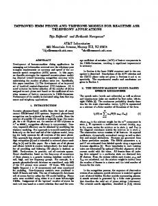
A. Digital micro-beamforming approach The received channel data are divided into several subgroups and each sub-group consists of N channels. Then, all channel data of different sub-groups are applied to the same delay pattern as shown in Fig. 1. This process is called presteering and all sub-groups share the same delay profile. The delay for the ith channel data is expressed as
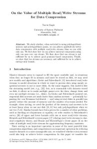
(PDF) when group sizes are set as 2 and 4, respectively. It should be noted that amplitude data are assumed to be independent for different channels. The distribution of the error function is nearly a zero mean Gaussian function. Therefore, the error between the original signal and the microbeamforming is modelled as a zero mean Gaussian distribution in this study. 0.016
−( xk − xi ) × sin θ , (1) c where xi , xk , c and θ are the channel i, non-delayed channel
−( xk − xi ) × sin θ −Δx × sin θ −Δx N ⎞ ⎛ = = × Δθ × ⎜ n − b ⎟ , 2 ⎠ c c c ⎝
0.01 0.008 0.006 0.004 0.002
(2)
where Δθ , n, Nb are the beam spacing, the nth beam (the current firing beam), total number of beams for a frame. With a sampling rate of fs, the delays for the digital pre-steering method can be expressed as
N ⎞ −Δx ⎛ × Δθ × f s × ⎜ n − b ⎟ . c 2 ⎠ ⎝
0.012
PDF
k in each sub-group, sound velocity, and the steering angle of the observation beam. In addition, the beam spacing (steering angle difference between two beams) is identical for each firing, (1) can be reformulated as
Group = 2 Group = 4
0.014
(3)
Since Δx , c, Δθ , and fs are constant, the required delay is only determined by the beam number, and the integer and fractional delay can be computed by (3). Finally, N channels are summed into one single output. All channels follow the same procedures. However, grating lobe and artifacts occur due to the reduction of channel counts. Therefore, the RF data are converted to baseband and digital micro-beamforming is only applied to the amplitude data while the phase data is unchanged. In this study, phase data are stored as 6 bits to preserve the quality of the output image.
0 -10
-5
0 Error value
5
10
Fig.2. Distribution of the error function.
C. Compensation method The goal of the compensation method is to apply a compensation factor to micro-beamformed data to reduce compression errors. In this study, the compensation factor is estimated by the mean value of the error function to minimize the mean square error. As previously described, the error function is modeled as a zero mean Gaussian distribution. The compensation factor is set as 0 to minimize the mean square error and no improvement can be achieved after the compensation process. However, if we can determine the original signal is larger or smaller than the micro-beamformed signal, the error function becomes a single-sided Gaussian distribution. The compensation factor can be derived by the centroid of the single-sided Gaussian distribution. This compensation factor can be applied to the micro-beamformed data at the software back end to reduce the compression errors. In addition, to identify the comparison between the microbeamformed signal and the original signal, a 1 bit header is used to indicate the output of the comparison. When the microbeamformed signal is larger than the original amplitude signal, then the header is set as 1. The header is set as 0 as the microbeamformed signal is smaller than the original signal. D. Encoding process of the proposed method
Fig. 1. Digital micro-beamforming approach.
B. Model of the error function In this study, amplitude data are suppressed by digital micro-beamforming approach. The error function between the original amplitude signal and compressed amplitude signal is investigated. Fig. 2 shows the distribution of the error function
Fig. 3 shows the encoding process of the proposed method for a 64 channel system. To convert the in-phase/quadrature phase data into amplitude/phase data, pipelined CORDIC algorithm is used where 64 channel data can be done in parallel. 6 bits are required for the phase data to preserve the image quality. Thereafter, the digital pre-steering method is implemented where the required integer and fractional delays can be computed by (3). The maximum integer delay is assumed to be 10 samples in this study. In addition, linear interpolation is used to compute the required fractional delay. After pre-steering process, N channels are summed into one single output (N is determined by the group size). As previously described, the compensation factor is stored and a 1 bit header is used for each channel to indicate the
comparison between a micro-beamformed signal and an original amplitude signal. The compensation factor and headers are stored in the header memory and compressed data are stored in the data memory for the subsequent decoding process.
Core i7 CPU with four-processors and an NVIDIA GeForce 740 GPU. In this study, the data-set was acquired from a tissue phantom and the parameters of the dataset are listed in Table I. TABLE I. PARAMETERS OF THE DATA SETS. Parameter Tissue phantom Number of channels 128 Number of samples per channel 2048 Number of beams 182 Sampling frequency (MHz) 13.89 Center frequency (MHz) 3.5 Number of bits per sample 14 Data acquisition time of 1 frame (ms) 26.84 Transducer type Phased array
A. Real time ability of the proposed method
Fig. 3. Block diagram of micro-beamforming approach with error compensation.
E. Decoding process of the proposed method
The processing times of CORDIC algorithm and the proposed encoder are evaluated in this study. First of all, the CORDIC algorithm requires 6 cycles to convert baseband data to amplitude/phase data. The processing time of digital presteering is determined by the computation times of integer and fractional delay processes. In this study, the maximum integer delay of the pre-steering process is assumed to be 10 cycles. In addition, 2 cycles are required for the fractional delay process. On the other hand, the number of cycles to compute the compensation process is given by the number of channels to compute one compensation factor. Assuming that one compensation factor is computed by M channels, the processing time requires log2 (M) cycles. In this study, 32 channel data are used to compute 1 compensation value; therefore, 5 cycles are required for the compensation process. Consequently, nearly 23 cycles are required for the encoding process. B. Compression efficiency This study employed two parameters to explore the performance of our proposed compression method: compression ratio and peak signal to noise ratio (PSNR). The compression ratio and PSNR are defined as
Fig. 4. Block diagram of decoding process of micro-beamforming approach with the proposed compensation method.
Fig. 4 shows the decoding process of micro-beamforming approach with error compensation in a GPU. First, the compensation factor is extracted and added/subtracted the compensation factor with the micro-beamfomed signal according to the header value. Then, the compensated amplitude data and the phase data are converted to in phase/quadrature phase data. III. RESULTS The imaging system of this study comprises the following two components: (1) a front-end simulation platform for verifying the encoding processes, and (2) a computer system where the host end is controlled by CPU and the device end is controlled by GPU. For the first platform, FPGA Virtex-6 was used. For the second platform, the data interface between the host and device used a 16-lane PCI-express 2.0 transfer interface. In addition, the computer system comprised an Intel
Compression ratio =
uncompressed data size compressed data size
PSNR=20 × log
MAX_VALUE ErrorRMSE
(4) ,
(5)
where MAX_VALUE is the maximum possible value of the output image, and the ErrorRMSE is the root mean square error of the original image and image reconstructed by compressed data. The compression ratio reported here is based on the comparison of compressed and uncompressed amplitude data, the original data size of uncompressed amplitude data was computed by (number of beams per frame) × (number of channels) × (number of amplitude data per channel) × (bit length per sample point). A higher compression ratio indicates a higher degree of suppression. PSNR indicates the difference between the compression and original data. A smaller PSNR indicates more errors occur in the original data, and thus, degrading the image quality. The results of compression ratios and PSNRs for group sizes as 2 and 4 are listed in Table II.
In addition, the mean square error (MSE) of beam data is also investigated to demonstrate the reduction of the amplitude error with the compensation approach. Fig. 5(a) shows the output image of the tissue mimicking phantom and Fig. 5(b) shows the MSE of beam data with and without the proposed compensation approach. Lower mean square errors can be obtained for each beam data when the proposed compensation method is used. TABLE II. COMPRESSION RATIOS AND PSNRS WITH AND WITHOUT THE PROPOSED COMPENSATION METHOD FOR GROUP SIZE EQUAL TO 2 AND 4 Compression ratio of PSNR amplitude data Group size = 2 2 63.13 without compensation Group size = 4 4 54.48 without compensation Group size = 2 1.75 66.54 with compensation 3.12 56.96 Group size = 4 with compensation
(a)
C. GPU performance of decoding process The transmission time to transfer the compressed data can be reduced according to the group size. When the group size is set as 4, there will be nearly a 3 fold improvement for data transmission. In addition, the decoding process only requires 5.74 ms. IV. DISCUSSION A. Improvement of data transmission As mentioned in Section I, to fulfill the real time transmission, data rate may up to several gigabytes per second (5-6 GB/s) to transmit massive ultrasound data from hardware front end to software back end system. With the assistance of our proposed method, transmission bandwidth of hardware interface is reduced. In addition, the proposed method integrates micro-beamforming and the compensation method into the previous transform-based architecture, and overall compression ratio can be improved by about 27~60%, reaching an overall compression ratio up to 6.3~7.1, which enables realtime data transfer via an USB 3.0 interface. B. Versatile for the linear array system The proposed method can also be applied to the linear array system. In this case, N channels are grouped and then N channels are summed into one single output without presteering process. The compensation approach is applied afterwards. However, the pitch size of a linear array is larger than the counterpart of the phased array, which decreases the correlation of the channel and increases errors, thus degrading the image quality. C.
Limiation
Phase data were set as 6 bits without any compression. Therefore, the overall compression ratio is mainly limited by phase data even the amplitude data can be further compressed.
(b) Fig. 5. (a) Output image of tissue phantom which consists of 182 beams, and (b) MSE of beam data with and without the proposed compensation approach.
V. CONCLUSIONS This study proposed the use of micro-beamforming with compensation approach to improve the performance of a GPUbased software beamformer. Peak-signal-to-noise ratio (PSNR) with error compensation has approximately 3 dB improvement as compared with the PSNR without compensation. However, lower compression ratio is achieved due to the need to include headers. A compression ratio around 3.18 is achieved when the group size is set as 4. REFERENCES [1]
[2] [3]
[4]
[5]
E. Oruklu, N. Jayakumar, and J. Saniie, "Ultrasonic Signal Compression Using Wavelet packet Decomposition and Adaptive Thresholding," IEEE Int. Ultrason. Symp, pp. 171175, Nov 2008. Y. F. Li and P.-C. Li, "Ultrasound beamforming using compressed data," IEEE Trans. Inf. Technol. Biomed., vol. 16, pp. 308-313, May 2012. U. W. Lok, ,G. W. Fan and P.-C. Li, "Lossless Compression with Parallel Decoder for Improving Performance of GPUbased Beamformer," IEEE Int. Ultrason. Symp., pp.561-564, July, 2013. Z. Yu, M.A.P. Pertijs, and G.C.M. Meijer, "A Programmable Analog Delay Line for Micro-Beamforming in a Transesophageal Ultrasound Probe," IEEE Solid-State & Integr. Circu. Technol. (ICSICT), pp. 299-301, Nov 2010. S. Blaak, Z. Yu, G.C.M. Meijer, C. Prins, C.T. Lancée, J.G. Bosch, N. deJong, “ Design of a micro-beamformer for a 2D piezoelectric ultrasound transducer”, IEEE Int. Ultrason. Symp., pp. 1338-1341, Sept. 2009.