Hindawi Publishing Corporation ISRN Electronics Volume 2013, Article ID 691930, 5 pages http://dx.doi.org/10.1155/2013/691930
Research Article Real-Time Implementation of Change Detection for Automated Video Surveillance System Sanjay Singh,1 A. S. Mandal,1 Chandra Shekhar,1 and Anil Vohra2 1 2
CSIR-Central Electronics Engineering Research Institute (CSIR-CEERI), Pilani, Rajasthan 333031, India Electronic Science Department, Kurukshetra University, Kurukshetra, Haryana 136119, India
Correspondence should be addressed to Sanjay Singh;
[email protected] Received 10 April 2013; Accepted 9 May 2013 Academic Editors: M. Hopkinson, M. Rawski, and M. Terauchi Copyright © 2013 Sanjay Singh et al. This is an open access article distributed under the Creative Commons Attribution License, which permits unrestricted use, distribution, and reproduction in any medium, provided the original work is properly cited. Change detection is one of the several important problems in the design of any automated video surveillance system. Appropriate selection of frames of significant changes can minimize the communication and processing overheads for such systems. This research presents the design of a VLSI architecture for change detection in a video sequence and its implementation on VirtexIIPro FPGA platform. Clustering-based scheme is used for change detection. The proposed system is designed to meet the realtime requirements of video surveillance applications. It robustly detects the changes in a video stream in real time at 25 frames per second (fps) in gray scale CIF size video.
1. Introduction Automated video surveillance systems are gaining importance due to their capability of performing automatic scene analysis. These systems can automatically select the frames of interest in a video stream by using scene change detection algorithms. The main challenge for designing these systems lies in their real-time performance requirements [1]. The software implementation of change detection algorithm running on general purpose processors could not achieve the frame rates required for real-time processing of a video stream for surveillance applications. Due to this reason, one needs to explore the different technologies possible for implementing real-time change detection system. One solution is to use special purpose digital signal processors, which are designed to execute some low level image processing operations very fast [2]. But the application like change detection uses a large range of low, medium, and high level operations. Therefore, this is not a good solution for achieving realtime performance. Alternative solutions are the design of application-specific integrated circuit (ASIC) or applicationspecific instruction set processor (ASIP) for change detection algorithm or use of field programmable logic devices. The main advantages of FPGAs (field programmable gate arrays)
over ASIC and ASIP are their ability to allow modification in the design in later stages of system development, architectural efficiency in terms of parallelism, shorter design time, cost efficiency, and real-time performance (high throughput). These features make FPGAs a suitable choice for implementing change detection in real time. This paper presents the design of a VLSI architecture for real-time change detection in a video stream and its FPGA implementation. Different algorithms have been proposed in the literature for change detection. A review can be found in [3]. These algorithms use different parameters for change detection and give different responses and performances for the same input image. We have used a clusteringbased scheme for change detection developed by Chutani and Chaudhury [4]. Their proposed approach significantly reduced the complexity and is much simpler as compared to other techniques. A dedicated VLSI architecture is developed for change detection using clustering-based scheme. Designed architecture is integrated with camera interface design and VGA display logic. Complete design is implemented on Xilinx Virtex-IIPro FPGA platform. Implemented system robustly detects the changes in real time in a video stream coming from camera.
2
ISRN Electronics
Camera
Video decoder board
Processing platform
Display device
Video decoder board
FX2
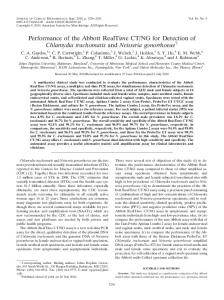
Figure 1: Block diagram of change detection system.
Camera interface module
24-bit RGB
Camera Virtex-IIPro FPGA platform
RGB to gray
VGA
VGA controller
(7) For a matching cluster, the frame number and centroid associated with the cluster node of the corresponding block are updated. For a given block, if no matching cluster is found, then a new cluster node is created by replacing the existing cluster node which has not been updated for the longest period of the time.
8-bit gray
3. Proposed Architecture
Input memory
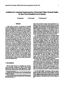
This section discusses the design and implementation of proposed architecture for clustering-based change detection scheme. This research paper is the extension of our earlier published work in conference [5]. The main components of a complete change detection system are analog camera, video decoder card for analog to digital video conversion, a platform for processing or running change detection algorithm, and display device. Figure 1 shows the basic block diagram of the system. In this implementation, captured video is digitized by Digilent VDEC1 video decoder board. Xilinx Virtex-IIPro Field programmable gate array (FPGA) board is used as processing platform. The change detected output is displayed on monitor via VGA connector on FPGA board. The video decoder board is connected to FPGA board through Hirose FX2 high-speed 100-pin connector. There are mainly five more blocks/modules running on FPGA in addition to change detection logic. These are camera interface logic, RGB to gray conversion, input memory buffer, output memory buffer, and VGA display controller as shown in Figure 2. The camera interface module receives the digital signals from video decoder card and extracts the 24-bit RGB data and video timing signals. The data is coming from the camera row by row. The 24-bit RGB color data is converted into to 8-bit gray data before storing it in input memory buffer. As clustering-based approach is based on the processing of 4 × 4 image blocks, the streaming video processing cannot be used. The four rows of image data are stored in input buffer memory before processing. The change detection architecture takes the inputs from buffer memory and processes the data. The change detection module output information is stored in output buffer memory. The VGA controller sends the change detected information to VGA port for display on monitor. It takes data from output memory buffer and timing information from camera interface module. The proposed VLSI architecture for clustering-based change detection scheme is shown in Figure 3. The first module is Block Centroid Computation Block. It computes the average centroid for 4×4 image block by taking gray pixel data from input memory. This is done by adding 16 pixel values of current block and then dividing the sum by 16. Division by 16 is done by shift operation. Computed block centroid value is stored in pipeline register. As mentioned in the algorithm section, clustering-based scheme stores centroid and frame number information for each 4 × 4 image block; therefore we need to assign unique identity for each block.
Change detection
Display monitor
(6) If the difference is below a threshold value, it is considered as a matching cluster.
Output memory
Figure 2: Proposed implementation data flow diagram.
The rest of the paper is organized in the following way: Section 2 briefly describes the clustering-based change detection scheme. In Section 3, we show the proposed architecture, its implementation, and working. Section 4 discusses the synthesis results and evaluates the practical tests which have proved the successful implementation and effectiveness of our implementation. Finally, we conclude the paper in Section 5.
2. Change Detection Algorithm The clustering-based change detection scheme used for change detection is briefly described in this section; for a more thorough description we refer to [4]. The main steps involved in the algorithm are given as follows. (1) Each incoming gray frame is partitioned into 4 × 4 blocks. (2) Each block is represented by a group of clusters, and each cluster contains centroid value and the frame number which updated the cluster last. (3) Initially, the cluster set of each block is initialized with a cluster having its centroid set to average color value of the corresponding block of the first frame. (4) Each block has 3 cluster nodes. (5) For every new frame, each block is compared with the corresponding cluster group. The difference is computed by taking Manhattan distance between average color value of the block and its centroid.
ISRN Electronics
3
From camera interface control signals
From input memory
Row and column address generation
Block centroid computation block
Row add
Frame number
Col add Pipeline registers
Row and col add Node frame no. memory
Update frame no.
MUX Node no. and frame no. Node no. and frame no.
Frame number
Block centroid Min (block cent − node cent)