Therefore, every major auto manufacturer and most major automotive sup- pliers must ..... model 24]. The course of the road is de ned by the center stripe which.
To appear in: H.-J. Bungartz, F. Durst, and Chr. Zenger (eds.): High Performance Scienti c and Engineering Computing, Lecture Notes in Computational Science and Engineering (Springer-Verlag, 1999)
Real Time Simulation and Online Control for Virtual Test Drives of Cars Cornelius Chucholowski1, Martin Vogel2, Oskar von Stryk2 , and Thiess-Magnus Wolter1 1 2
TESIS DYNAware GmbH, Implerstra�e 26, D-81371 Munchen Technische Universitat Munchen, Lehrstuhl fur Hohere Mathematik und Numerische Mathematik, D-80290 Munchen, http://www-m2.ma.tum.de/
Abstract. Virtual prototyping plays a key role in modern car engineering. For
virtual test drives of entire cars in the computer, mathematical and computational models of the vehicle, the road, and the driver are presented. The numerical simulation must be performed in real time for application in Hardware-in-the-Loop experiments. Numerical results are presented for the ISO slalom test.
1 Introduction Active vehicle control units (ACU), such as anti-lock braking systems (ABS) or electronic stability programs (ESP), are used for improving the driving comfort and safety of modern cars [1]. Thus, the car design and the dynamical driving properties (handling) become more complex than ever before. Therefore, every major auto manufacturer and most major automotive suppliers must use a virtual prototyping software to cut the product development time and cost, and to improve the design quality. To realistically \test drive" entire vehicles in the computer, computer models of whole cars, complete with suspensions, powertrains, engines, steering mechanisms, and active control units are needed. The models must then be exercised under various road conditions in the computer, performing every maneuver normally run on a test track. Thus, handling characteristics of the physical prototype such as body roll, ride quality including vibration and bumps, vehicle safety, and performance parameters can be predicted precisely. Road parameters such as weather and road surface conditions, which vary widely on physical test tracks, can be controlled easily for virtual test drives. Active vehicle control units are feedback control systems which require an intense testing for various road conditions and for various car designs. Hardware-in-the-Loop (HIL) experiments provide e�cient, cost e�ective, and save tests for ACUs. Here, the ACU in a test bed is linked to a full car dynamics simulation in real time (Fig. 1). For rating the handling and driveability properties of a virtual prototype, the performance of the closed loop of driver | vehicle | environment
2
C. Chucholowski, M. Vogel, O. von Stryk, T.-M. Wolter
must be investigated ([26], Chap. 6.1). In this paper, we describe special models for the virtual vehicle, the virtual driver, and the virtual environment which are well suited for HIL experiments. Numerical results for virtual test drives of a typical handling maneuver, the ISO slalom test, with di�erently designed cars are given.
2 The Virtual Car For modelling the vehicle dynamics, the car and its components are described by mechanical systems that are interconnected by joints, and that move or articulate in three dimensions. The mechanisms, linkages, or other mechanical subsystems undergo large displacement motions. The e�ects of applied and inertial forces must be taken into account. General purpose methods for multibody systems (MBS), such as [3,13] or [18] (survey in [19]), use the descriptor form for the equations of motion. The virtual prototype is described by a large-scale system of di�erential-algebraic equations (DAEs) of index 3 [21]. Currently, no numerical methods for direct and reliable integration of general systems of index greater than two are available. Therefore, special techniques such as index reduction, coordinate partitioning, projection etc. have to be applied in order to beware of the \drift-o�" of the algebraic constraints [6,21].
2.1 VEDYNA: Numerical Simulation of Full Car Dynamics VEDYNA is a special purpose method for vehicle dynamics simulation in real time [2]. The car is modelled as a multibody systems, i. e., a system of rigid bodies with kinematic joints and force elements (springs, dampers, active components), linked with suitable tire models, models for the steering mechanism and the powertrain. In VEDYNA as few parts as possible and as many parts as necessary are choosen for the MBS, in order to reduce the computational time needed for the numerical simulation. The numerical simulation of large MBS with general purpose methods such as [3,13,18,19] may be very time consuming. The computation of one real time second of full car dynamics may in some cases take up to 8000 seconds CPU-time on a modern workstation with a general purpose method [23]. The general purpose methods might be suitable for highly detailed simulations where computational time is not crucial. However, a fast computation is advantageous for virtual prototyping, and can be obtained by utilizing the special structure of the car model for the numerical simulation. VEDYNA is real time capable, i. e., the computation of one second of vehicle dynamics takes less than one computational second on a reasonable hardware. The computation is up to three orders of magnitude faster than general purpose methods. This enormous speedup is achieved by utilizing the
Virtual Test Drives of Cars
3
structure of the problem in every step of modelling and simulation, and by using a multi-processor hardware for the computation. A tailored MBS model, optimized programs for the equations of motion, and a tailored numerical integration method lead to a fast, reliable, and realistic simulation tool. The dynamical model of VEDYNA consists of three basic parts: a system of rigid bodies for the car structure, a submodel for the drive train, and submodels for the steering mechanism and the tires. The MBS for the car structure consists of one body for the vehicle itself, four so-called wheel bodies and four wheels. That makes a total of nine rigid bodies. The wheel bodies are used to describe the masses of the axles moving relative to the vehicle body, whereas the wheels are attached to the wheel bodies with one rotational degree of freedom [17]. As part of the MBS the wheels are considered to be rigid bodies, since their inertias with respect to the axes of rotation do not change signi cantly. Therefore, the deformation of the tires is not considered within the MBS. However, the tire deformation a�ects the dynamical behavior of the system. Therefore, spring and damper elements are used to describe the lateral, longitudinal, and vertical deformation of the tires for computing the tire forces by a semi-empirical tire model [9,14,17].
2.2 Equations of Motion Following the approach of [17], the equations of motion are derived using Jourdain's Principle. Special minimal coordinates and generalized velocities are choosen. This results in a minimal number of ordinary di�erential equations (ODEs) (6), (7), with a full mass matrix V for the vehicle structure. In general purpose methods [13,18,19], general coordinates are used resulting in DAEs of index 3. The advantages are the resulting almost diagonal, easy to invert mass matrices. The price to pay numerically are the algebraic equality constraints which have to be handeled by the numerical integration method. On the other hand, VEDYNA utilizes the structure of the multibody system, i. e., the structure of the full mass matrices S (steering mechanism), P (powertrain), and V (vehicle MBS), to solve e�ciently the linear systems (2), (4), (6) for the derivatives of the generalized velocities. The ODE formulation obtained by minimal coordinates turns out to be advantageous, since the basic vehicle structures are well known. The basic equations of motion in VEDYNA consist of 24 rst order ODEs for the dynamical behavior of the vehicle body and the axles (Eqs. (6) and (7)) and 8 ODEs for spring and damper elements describing the deviations of the tires (Eq. (1)). The dynamical model of the powertrain consists of 19 ODEs including the four equations (4) and (5) for the angular velocities of the wheels. Five additional ODEs describe the dynamics of the steering M
M
M
M
4
C. Chucholowski, M. Vogel, O. von Stryk, T.-M. Wolter
mechanism (Eqs. (2) and (3)): _T = stat ? T (1) (2) S _S = S ( S S ) _S = S S (3) (4) P _P = P ( P P ) _P = P P (5) (6) V _V = V ( V V S S P P ) _V = V?1( V ) V (7) Here, T : IR ! IR8 denotes the coordinates for the lateral and longitudinal deviations of the tires. The matrices and are diagonal matrices of damping and sti�ness coe�cients. The vector stat describes the forces computed by a statical, semi-empirical tire model. We have generalized, minimal coordinates S : IR ! IR2 (steering), P : IR ! IR7 (powertrain), V : IR ! IR12 (vehicle) and generalized velocities S : IR ! IR3 , 12 12 P : IR ! IR , V : IR ! IR . The equations for the steering model, the powertrain model, and the vehicle structure are treated as separate systems, where only couplings via the generalized forces V occur. I. e., the weak couplings between the subsystems in the total mass matrix are neglected resulting in three \independent" mass matrices S , P , and V . Some terms of the right hand side with second and higher order derivatives of the minimal coordinates can be neglected without a signi cant loss of accuracy [17]. The tire forces have a large impact on the dynamical behavior of a car. The applied semi-empirical tire model describes the behavior of a real tire [9,17]. About 80 parameters, which can be measured or estimated, enter the model for each tire in VEDYNA. The model covers di�erent driving situations, including e�ects at the driving limits such as sliding and spinning. The di�erential equations are solved e�ciently by a tailored, semi-implicit, one-step Euler method [17]. By utilizing the special structure of the ODEs, the numerical integration is quite fast and su�ciently accurate. The numerical integration can be performed on a low-cost parallel computer, e. g., a dSPACE PC-board with ve TI-40 processors. Thus, the numerical simulation can be performed in real time even for stepsizes of less than 1ms. Two processors are needed for the computation of the tire forces, two more processors compute the axle dynamics. The master processor does the remaining computations and controls the simulation (see Fig. 1). D y
M
M
M
F
z
Q
y
V
z
Q
y
V
z
Q
y
K
C y
y
;z
z
y
;z
z
y
;z
y
;y
;z
;y
;z
z
y
D
C
F
y
y
y
z
z
z
Q
M
M
M
2.3 Hardware-in-the-Loop Experiments A new component of a physical prototype, e. g., an ACU, can be tested e�ciently and safely under various road conditions and for various car designs in an HIL test bed. Only the component to be tested has to be present as
Virtual Test Drives of Cars Slave_3 Start
Slave_1 Start
Master Start
Slave_2 Start
5
Slave_4 Start Loop Entry Point
"Driver"
Hardware-in-the-Loop Analog/Digital Converter
Input Vehicle Brakes
"Cockpit"
Transformations
Brake torque
Gear Tire 1
Front
Tire 2
Suspension
Rear Drive torque
Suspension
Tire 3 Tire 4
Drive line
ABS Control Unit
Brake Actuator
Output Online Animation Integration Loop Exit Point
Fig. 1. An example for a Hardware-in-the-Loop: A braking system with an ABS control unit linked to the parallel simulation of the vehicle dynamics in real time.
the physical prototype, whereas the car (vehicle dynamics), the environment (road, weather) and the driver (guidance scheme) are simulated by the computer software. Thus, to realistically test drive a virtual prototype, also a virtual driver and a virtual road are needed (see Sects. 3 and 4). In HIL test beds even long term \test drives" can be performed without leaving the laboratory. Therefore, full car dynamics simulation in real time must be linked to the test bed (Fig. 1). The unit to be tested, e. g., an ABS control unit, receives \sensor" signals from the simulated car ride in the same way as from the physical one. The output and the e�ect of the active control unit, e. g., the brake pressures, are measured and provided as an input to the simulation (see Fig. 1). Standard handling maneuvers for ride comfort and handling must be investigated in the computer, such as the ISO/FDIS 3888 lane change maneuvers, the ISO 7975 braking in a turn maneuver, the ISO slalom test (Sect. 5), or the \moose test".
3 The Virtual Environment For the realistic test drive of a virtual car, various weather and road conditions must be considered. A virtual, but realistic road model is needed for describing public roads and test courses. Also, three-dimensional driving effects such as banked curves, hills, and bumpy roads must be modelled. The smoothness of the road surfaces may also vary. Traction values of the road
6
C. Chucholowski, M. Vogel, O. von Stryk, T.-M. Wolter
surface depend on weather conditions (dry, wet, or icy road). Any realistic road model must satisfy these requirements. For use with VEDYNA, we developed a tailored and parameterized road model [24]. The course of the road is de ned by the center stripe which is a piecewise de ned curve. Its curvature is a piecewise linear function of the arc length. A variable transverse pro le is added for representing threedimensional road properties such as bumps and dips. The parameters of the transverse pro le describe di�erent weather conditions by di�erent traction values. The actual tire model is selected online depending on these parameters [2]. The road model is easy-to-use. A realistic road can already be obtained with quite few parameters, although the level of detail can be adapted. This road model is suitable for real time simulation. We refer to [24] for details. Wind forces and moments result in external forces applied to the multibody system of the car [14,17].
4 The Virtual Driver The virtual driver must simulate the control actions of a vehicle's driver | steering, braking, accelerating, gear shifting, and operating the clutch | as the vehicle undergoes a variety of maneuvers. In this context, we do not want to investigate the speci c biomechanical or psychological behavior of a human driver. A synthetical driver is needed instead for investigating the \objective" handling properties of the virtual prototype. Also, information can be used for the virtual driver which a human driver usually does not have (and cannot use directly) such as traction values at the tires or the exact side slip angle. However, the online guidance scheme, i. e., the virtual driver, must be able to guide the virtual car, i. e., the full car dynamics simulation, at the driving limits close to the performance of human test drivers with physical prototypes on a closed course. A new guidance scheme [24,25] has been developed for use in combination with the vehicle dynamics simulation program VEDYNA (Sect. 2.1). As demonstrated by several computed test drives, the virtual driver is able to guide the virtual car along a nominal path on a virtual road at a high speed and in extreme maneuvers where skidding and sliding e�ects take place. The synthetic driver is based on a nonlinear position control of the center of gravity of the car on the road. The input of the control law is the actual position and the velocity of the center of gravity and their set points (\targets") [12,24,25]. The nonlinear control law is derived by using a single track model of a car [16], and the theory of nonlinear system decoupling and control originally developed for robot control [7,8]. The output of the control law are values of the front lateral force and the longitudinal force which have to be achieved by choosing appropriate steering angles and brake or gas pedal positions of the virtual car.
Virtual Test Drives of Cars
7
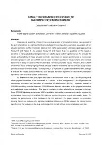
Fig. 2. The computed ISO slalom tests with a standard sports utility car (on the left hand side) and an overloaded car (on the right hand side).
8
C. Chucholowski, M. Vogel, O. von Stryk, T.-M. Wolter ISO Slalom Test 4
[m]
2 0 -2 -4 -50
0
50
100 150 200 Roadlength [m]
250
300
Fig. 3. The computed path of the center of gravity of the car during the rst virtual ISO slalom test.
The set point for the center of gravity travels along a nominal path. Its velocity history can either be prescribed in advance or can be computed online depending, e. g., on the parameters of the virtual car and the properties of the road such as the curvature [24,25]. Although the simulation of a human driver's behavior is not intended, a performance close to human test drivers is desired, e. g., to guide a car accurately along a nominal path even at a high speed. Spinning of the car or similar e�ects are faced by appropriate pedal positions and steering angles. In rst virtual test drives, the guidance scheme did keep the center of gravity near the nominal path in various situations at the driving limits.
5 Virtual Test Drive of the ISO Slalom Test Virtual test drives of typical handling maneuvers include the ISO single and double lane change maneuvers, the ISO slalom test, or the now famous \moose test". Here, we investigate the performance of a standard sports utility car undergoing the ISO slalom test. The cones are placed equidistantly at a distance of 23 m. The prescribed drive-through speed is 55 km/h (about 34 mph). The vehicle mass is 1600 kg, the wheel base is 2.6 m, and the wheel track is 1.5 m. The rst virtual test drive is performed with the standard car, whose center of gravity is 0.67 m above the ground. For the second test drive we assume a much higher position for the center of gravity, namely 0.90 m above the ground. This can be caused by a heavy load on the top of the car. Then the axle design is not tailored to the new position of the center of gravity. The set point for the horizontal position of the center of gravity of the car travels through the cones along a sine function with a maximum amplitude
Virtual Test Drives of Cars
9
ISO Slalom Test, Well Designed Car
Roll angle [deg]
10
5
0
-5
-10 10
15
20
25 Time [s]
30
35
40
Fig. 4. The computed roll angle of the car during the rst virtual ISO slalom test. of 1.9 m at the cones. During the computed test drive, the virtual driver keeps the center of gravity close to the set point and therefore the car follows the same sine function. The well designed car passes the slalom test without troubles, although the maximum roll angle (� 8� ) is quite large (see Figs. 3 and 4). The bad designed car has the same suspension tuning, but its center of gravity is 0.23 m higher. This car fails the slalom test at the same speed (see Fig. 2). Already at the rst cone, the roll angle becomes too large and the car ips over.
6 Conclusions For rating the performance of active vehicle control units by virtual test drives in Hardware-in-the-Loop test beds, computer models for the virtual car, the virtual environment, and the virtual driver are presented. Numerical and computational results for a standard handling maneuver demonstrate the e�ciency of this approach.
References 1. Ackermann, J. (ed.): Regelungstechnik im Auto. at { Automatisierungstechnik 44 (1996) 5 2. Anonymous: VEDYNA User's Guide. TESIS DYNAware GmbH, Munchen (1997) 3. Anonymous: ADAMS: Mechanical Dynamics, Inc., http://www.adams.com/ 4. Donges, E.: Experimentelle Untersuchung und regelungstechnische Modellierung des Lenkverhaltens von Kraftfahrern bei simulierter Stra�enfahrt. Darmstadt: Technische Hochschule, Diss. (1977)
10
C. Chucholowski, M. Vogel, O. von Stryk, T.-M. Wolter
5. Dreyer, W.: Zum langsdynamischen Verhalten des Regelkreises Fahrer { Kraftfahrzeug. Braunschweig: Technische Universitat, Diss. (1980) 6. Eich-Soellner, E.; Fuhrer, C.: Numerical Methods in Multibody Dynamics. Stuttgart: Teubner (1998) 7. Freund, E.: Fast Nonlinear control with arbitrary pole-placement for industrial robots and manipulators. Intern. J. Rob. Res. 1 (1982) 1, 65{78 8. Freund, E.; Syrbe, M.: Control of industrial robots by means of microprocessors. In: New trends in system analysis. Proc. Int. Sympos. Versailles 1976. Lecture Notes in Control and Information Sciences 2 (1977) 167{185 9. Gipser, M.: DNS-Tire { ein dynamisches, raumliches, nichtlineares Reifenmodell. In: Berechnung im Automobilbau, VDI-Bericht Nr. 650, Dusseldorf: VDIVerlag (1987) 115{135 10. Horn, A.: Fahrer { Fahrzeug { Kurvenfahrt auf trockener Stra�e. Braunschweig: Technische Universitat, Diss. (1985) 11. Kollatz, M.: Kinematik und Kinetik von linearen Fahrzeugmodellen mit wenigen Freiheitsgraden unter Berucksichtigung der Eigenschaften von Reifen und Achsen. Fortschr.-Ber. VDI Reihe 12 Nr. 118. Dusseldorf: VDI-Verlag (1989) 12. Mayr, R.: Verfahren zur Bahnfolgeregelung fur ein automatisch gefuhrtes Fahrzeug. Dortmund: Universitat, Diss. (1991) 13. Orlandea, N.: ADAMS (theory and applications). Vehicle System Dynamics 16 (1987) 121{166 14. Popp, K.; Schiehlen, W.: Fahrzeugdynamik. Stuttgart: Teubner (1993) 15. Reichelt, W.: Ein adaptives Fahrermodell zur Bewertung der Fahrdynamik von PKW in kritischen Situationen. Braunschweig: Techn. Universitat, Diss. (1990) 16. Rieckert, P.; Schunck, T. E.: Zur Fahrmechanik des gummibereiften Kraftfahrzeugs. Ing.-Archiv, Bd. XI (1940) 210{224 17. Rill, G.: Simulation von Kraftfahrzeugen. 1. Au . Braunschweig: Vieweg (1994) 18. Rulka, W.: SIMPACK, ein Rechenprogramm zur Simulation von Mehrkorpersystemen mit gro�en Bewegungen. In: Proc. Finite Elemente in der Praxis, Computergestutztes Berechnen und Konstruieren. Reutlingen: T-Programm (1989) 206{245 19. Schiehlen, W.: Multibody Systems Handbook. Berlin: Springer (1990) 20. Senger, K.-H.: Dynamik und Regelung allradgelenkter Fahrzeuge. Fortschr.Ber. VDI Reihe 12 Nr. 126. Dusseldorf: VDI-Verlag (1989) 21. Simeon, B.: MBSPACK { Numerical integration software for constrained mechanical motion. Surv. Math. Ind. 5 (1995) 169{202 22. Speer, Th.: Kontinuierliche Runge-Kutta-Approximationen fur steife Di�erentialgleichungen mit Anwendung in der Fahrzeugdynamik. Munchen: Technische Universitat, Diss. (1989) 23. Tscharnuter, D.; von Stryk, O.; Bulirsch, R.: Zur Problematik der Antriebsstrangsimulation mit den Programmpaketen ADAMS, DADS und SIMPACK. Studie fur die BMW AG. Munchen: Technische Universitat, Lehrstuhl fur Hohere Mathematik und Numerische Mathematik (1996) 24. Vogel, M.: Fahrbahnmodellierung und Kursregelung fur ein echtzeitfahiges Fahrdynamikprogramm. Munchen: Technische Universitat, Lehrstuhl fur Hohere Mathematik und Numerische Mathematik, Diplomarbeit (1996) 25. Vogel, M.; von Stryk, O.: A guidance scheme for full car dynamics simulations. (in preparation) 26. Zomotor, A.: Fahrwerktechnik: Fahrverhalten. 2. Au . Wurzburg: Vogel (1991)