22nd International Symposium on Automation and Robotics in Construction ISARC 2005 - September 11-14, 2005, Ferrara (Italy)
1
Real-Time, Three-Dimensional Object Detection and Modeling in Construction Jochen Teizer, Frederic Bosche, Carlos H. Caldas, Carl T. Haas, and Katherine A. Liapi
Abstract — This paper describes a research effort directed to produce methods to model three-dimensional scenes of construction field objects in real-time that adds valuable data to construction information management systems, as well as equipment navigation systems. For efficiency reasons, typical construction objects are modeled by bounding surfaces using a high-frame rate range sensor, called Flash LADAR. The sensor provides a dense cloud of range points which are segmented and grouped into objects. Algorithms are being developed to accurately detect these objects and model characteristics such as volume, speed, and direction. Initial experiments show the feasibility of this method. The advantages and limitations, and potential solutions to limitations are summarized in this paper.
I. INTRODUCTION
T
HE construction environment is dominated by the continuous change in the location of labor, materials, and equipment. Size, position, and motion of such project elements play a critical role in many work tasks. Graphical three-dimensional forms can assist project managers to conduct construction activities more safely, efficiently, and effectively. Connecting real-time models to management tools can improve equipment controls such as heavy lifting for structural assembly and obstacle avoidance. Thus, constructing an automated real-time model of actual site conditions can provide project processes with information regarding objects’ dimensions and location over time. The focus of the research is on obstacle avoidance for the safe navigation of heavy equipment and robot automation. More applications inside and outside the construction domain exist This work is supported in part by the National Science Foundation under grant CMS 0409326 and the National Institute of Standards and Technology under solicitation number SB1341-04-Q-0898. Jochen Teizer is a Ph.D. candidate with the Department of Civil, Architectural and Environmental Engineering at The University of Texas at Austin, Austin, TX, 78712 USA (phone: 512-554-7857; fax: 512-471-3191; email:
[email protected]). Frederic Bosche is a Ph.D. candidate with the Department of Civil, Architectural and Environmental Engineering at The University of Texas at Austin, Austin, TX, 78712 USA (e-mail:
[email protected]). Carl H. Caldas is Assistant Professor with the Department of Civil, Architectural and Environmental Engineering at The University of Texas at Austin, Austin, TX, 78712 USA (e-mail:
[email protected]). Carl T. Haas is Professor with the Department of Civil Engineering at the University of Waterloo, Waterloo, Ontario, Canada N2L 3G1. He is the Canada Research Chair in Construction and Maintenance of Sustainability (email:
[email protected]). Katherine A. Liapi is Assistant Professor of Architectural Engineering at the University of Patras, Panepistimioupolis, Rio, 26500, Patras, Greece (email:
[email protected]).
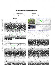
and can benefit from this research approach. The ultimate research objective is the development of algorithms capable of autonomously identifying and tracking objects which finally are displayed in a three-dimensional workspace model in realtime. II. FRAMEWORK FOR 3D MODELING IN REAL-TIME This section presents an overview of the framework for three-dimensional (3D) modeling in real-time. In Fig. 1 the framework is displayed. The proposed world model can be described in two parts: The field of view (FOV) of the actual sensor and the entire space of operation. One analogy is the FOV of the human eye and the world itself. Then, a computergenerated three-dimensional model represents the FOV of one or multiple sensors providing information to support the world model. In this research the sensor provides range information that is interpreted and processed, leading to a computer 3D model. The processing of sensing data can also enable the computation of velocity, position, and orientation. Collected and stored data can provide useful information from static and dynamic situations in various frame shots, which further can be used to locate, track, and plot objects within the sensor’s field of view. For each frame shot, the range camera captures range and intensity values. Once each frame is processed, its correlation to the next by or to other frames needs to be considered. After each frame is processed, the world model needs to be updated with new information or information which further expands the world model. With additional information provided from other intelligent devices like RFID and GPS, as well as using a priori knowledge (e.g. from previous model updates or CAD models), certain data like location, distance and intensity, and condition of objects within the reach of the sensors can be obtained. Other sensors and a priori knowledge from CAD models can help to make the overall process of modeling in 3D more meaningful since they put the gathered information of a range camera in to retrospective to each other and can be used for pre- or post-analysis. This could mean that range information can update the a priori known location and orientation information provided from a CAD model. RFID information may provide item descriptions for safe handling. GPS can provide the initial sensor location. Finally, any approach for automated navigation, path planning or tracking requires real-time data acquisition and processing to be able to
ISARC 2005 address timely adjustments in the world environment. Two approaches to detect and model objects along with the creation and maintenance of a world model are currently considered: • Convex hull modeling, which was previously used and developed for rapid 3D modeling at the University of Texas at Austin [1], as well as • Occupancy grids, a method to model 3D spaces, which is recently applied at different research institutions. Both approaches are described in the following paragraphs. III. CONVEX HULL BASED MODELING APPROACH The research team investigated an initial approach by processing the range data from the 3D range camera to obtain convex-hulls. Procedure and findings of the convex hull based modeling are further described.
Fig. 1. Framework for three-dimensional modeling in real-time.
2
Codes to model convex-hulls from raw data were partially developed in previous work conducted by our research team, but were based on single beam range lasers collecting sparse point clouds [2]. Since current research efforts use a Flash LADAR, the existing sparse point cloud algorithms needed to be modified to comply with dense point clouds. Fig. 2 presents a successful example to model an outdoor scene containing a car based on dense range data. Due to hardware limitations of the sensor, corners of the dense range image showed wrong distance measurements and subsequently were removed before creating a convex hull. Fig. 2a shows the raw range data collected by the Flash LADAR. In a matrix of 124x160 pixels each pixel refers to one distance measurement in the scene. The next step was to erase noise by smoothening (Fig. 2b). This reduced individual measurement errors, however, as
ISARC 2005 expected, smoothening blurred the data of the original range image. In the segmentation step (Fig 2c) points belonging to the object and not belonging to it were separated. The following step applied a modified convex hull algorithm fitted to range data. In retrospective, segmentation required most of the time and was unexpectedly inaccurate since parts of cars were dropped out of the region of where the car actually belongs. Despite the time required to segment and its results, the segmentation did not affect the outcome of the convex hull. The car was successfully bounded in a convex hull (Fig. 2d) since the car edges were not removed from either smoothing or segmentation. However, smoothening increased the objects’ boundaries and created a larger volume than the original object actually has. It can be expected that similar results can be achieved with heavy construction equipment or any kind of object in an outdoor environment. Other effects reduced the modeling performance during experiments in outdoor environments. Since the sensor’s distance measurement is based on the Time-Of-Flight (TOF) principle, computational reasons require that enough signal strength of the emitted near infrared sources is backscattered to the Charged Coupled Device (CCD). However, bright sunlight influenced the emitting source. Experiments demonstrated that only those parts on the target object returned the emitted signal successfully, which were reflected from shadow parts of the car. In controlled indoor environments, frame subtraction (T-(T1)) may allow clustering points immediately and may not require stepping through the time intensive segmentation step. In general, most likely a priori knowledge is available. A
(a)
(b)
(c) (d) Fig. 2. Modeling a car using the convex-hull based algorithm: (a) raw scanned data, (b) smoothed data, (c) segmentation and object detection, and (d) convex-hull encompassing the detected object.
3
priori knowledge is defined as any kind of observation of the same scene or FOV at any time before. This can be very useful, since with frame subtraction only changing range points need to be processed. In this situation, single or multiple objects can be filtered out easily and then processed to a 3D model. Modifying the existing sparse point cloud approach to dense range point clouds obtained satisfactory results. It showed that models can be processed with quite sufficient precision. However, it also exposed the problem of the time required to process convex-hulls compared to the acquisition time. Processing a typical image (19,840 points) required about one minute in experimental context. The timing issue could be improved but probably not to a frequency of 1Hz or higher. Therefore, the team started to investigate another approach. IV. OCCUPANCY GRID BASED MODELING APPROACH The second approach uses occupancy grids that were first pioneered by H. Moravec and A. Elfes in 1985, using a sonar range finder [3]. Occupancy grids allow dividing the world’s space into a three-dimensional grid system. The three-dimensional character of the grid system allows mapping object locations for safe path planning and tracking. On construction sites, especially in robot driven environments like automated steel erection [4], such a grid system can store the location information of obstacles. This data can be used to calculate the safe navigation path of the robot. The sensor used in this research provides intensity and range values to each pixel in the sensor’s FOV at the same time. The algorithms being developed in this research are based on range information only. However, using intensity as additional information source to describe and model scenes may further improve the data processing in speed and precision. Using intensity as additional information can lead future research. A. Description This method could help to wisely reduce the amount of data prior to attempting any segmentation. Fig. 3 shows the path for occupancy grids in the world model process. Data points can be gathered into each one of the cells of a predefined grid. If enough data points are present in a cell, the cell is considered full. All the data that it encompasses is condensed to one value: the full cell, or 1 for full and 0 for empty. Therefore, while reducing the amount of data prior to segmenting it, it also serves as a noise filter since each cell that does not include enough data points will not be considered full. Then, object detection can be performed using similar methods as in the convex-hull based approach. The lower amount of data helps reducing the processing time to reach effective real-time application. B. The use of occupancy grids in this research In Fig. 3 the flowchart demonstrates the principle of
ISARC 2005 occupancy grids for this modeling research. Subfigures 3a to 3f explain how occupancy grids are applied to an outdoor scene of moving cars. Fig. 3a: The surrounding and what we can see is defined as the entire world. Static and moving targets such as cars at a road crossing are part of the entire world. The 3D range camera is mounted on a tripod and connected to a computer with capable processing software to create a world model based on occupancy grids. In the future, sensor and processing unit may significantly shrink in size and purchase cost. Fig. 3b: The sensor emits its infrared light in the field of
4
view (FOV). The backscattered waves are collected by the sensor’s lens and pre-processed. The output is a matrix of range data. In this scene, the FOV limits the capturing of the entire world. Some objects appear only with parts in the FOV and other physical obstructions like occlusions hinder them from being seen. Fig. 3c: The 3D range camera provides intensity and range information. The position, orientation and speed of the sensor in the world model are known. Since the objective of this research is to rely on range information solely, only range information will be used for processing. Still, intensity will be
Fig. 3. Occupancy Grid based real-time 3D modeling with an example in transportation.
ISARC 2005 stored automatically and can play an important part in future analysis. The world model (entire space) and sensor’s FOV need to be divided into a 3D grid system with identical parameters. The user is able to choose its parameters, such as: • Grid size (depending on application), • %-value of similar and deviation of range values needed to fill each cube This allows determining the metrics of how to size and fill the cubes and how to perform analysis. Metrics will also verify benchmarking tests and allow useful feedback, such as the comparison of original vs. measured volumes. Fig. 3d: Assuming that the initial world model was empty, a first frame shot with only static objects can model the static scene. To filter out objects faster, the actual frame shot is always compared to the previously stored frames in the world model or actual frame grabbing process. Subsequently, if the world model was initially empty and no grids or cubes were filled through static or moving objects, subtraction of the “empty” frame with a frame containing range information results in only those range points which changed. Within the FOV such range points will be displayed in 3D. Once range points have met the occupancy filling criteria (%-value defined at program start), the cubes (e.g. cars represent “moving” pixels) are filled. Only the parts of the left car which are in the FOV are filled with cubes. Cubes which are filled and next to each other with at least one full face (no edges or corners) in 3D are grouped into a single object consisting of multiple cubes. Frame subtraction allows distinguishing between the object (car) from the ground (road). Fig. 3e: The world model may contain a priori information which needs to be updated. This a priori information can be obtained from previously stored information as well as from other sensors or CAD data. Already processed and new range information is used to generate and update the world model. Fig. 3f: Frequent updates are desirable to get timely information of the location of obstacles and/or for path planning. Grouping cubes to objects and defining Center of Gravity (COG) allows path planning and tracking. The final output of modeling with occupancy grids is a world model which includes the FOV of sensor(s) and offers real-time updates for efficient and effective tracking and safe path planning.
The range sensor used in this research is a SwissRanger2 (a 3D range camera [5]) and was mounted on a speed-controlled and computer steered horizontal gantry. This allows having the sensor in static and moving positions and perspectives to simulate the on-site navigation of construction equipment as realistic as possible. Target objects to be detected are typical in volume and shape to those to be found on job sites. Direction and speed of objects in experiments are close to real-life situations. Repetitive indoor and outdoor experiments are analyzed and benchmarked. Once the combinations of experiments are conducted, analysis will show the performance of the approached modeling methods. More results and limitations of initial experimental results can be found in [6] and [7]. VI. CONCLUSION This paper presented a framework for real-time, threedimensional object detection and modeling targeting the area of safer navigation of heavy construction equipment. Two approaches, convex hulls and occupancy grids, were introduced. While each approach has the potential to successfully and rapidly process range point clouds into a meaningful three-dimensional model, initial experiments resulted in favoring the occupancy grid approach due to the capability to reach the research objective of modeling at frequencies of 10Hz or more. Future research work will integrate scanned range data into a world model and allow the combination and merging with useful information of other data from RFID, GPS, or CAD for safer navigation and tracking of heavy equipment, robots, materials or humans. This research may be applied to other areas in the detection, identification and modeling of construction environments. REFERENCES [1]
[2]
[3]
[4]
V. EXPERIMENTAL SETUP The goal of experiments is to create a system characterizing construction-typical environments which at the same time allows repetitive experiments in most or all situations. Target objects are described and their specifications are given. The experimental setup is based on the principle “from simple to complex”. This means initial experiments have one static object. Through the stages of experiments, the complexity will increase to where more than one static or moving target is in the sensor’s FOV at the same time.
5
[5]
[6]
[7]
C. Kim, C.T. Haas, K.A. Liapi, J. McLaughlin, J. Teizer, and F. Bosche. “Rapid Human-Assisted, Obstacle Avoidance System Using Sparse Range Point Clouds,” Conference Proceedings. Earth & Space, The 9th ASCE Aerospace Division International Conference, Houston, 2004. S.-W. Kwon, F. Bosche, C. Kim, C. T. Haas, and K. A. Liapi, “Fitting Range Data to Primitives for Rapid Local 3D modeling Using Sparse Point Range Clouds,” Automation in Construction, 2004: vol. 13, p. 6781. H. Moravec and A. Elfes,” High-resolution maps from wide-angle sonar,” IEEE Int'l Conf. on Robotics and Automation. 1985. St. Louis, Missouri. A. Lytle, K. Saidi, R. V. Bostelman, W. C. Stone, and N. Scott, “Adapting a teleoperated device for autonomous control using threedimensional positioning sensors: experiences with the NIST RoboCrane,” Automation in Construction, 2004, vol.13, no.1, 101-118. T. Oggier, M. Lehmann, R. Kaufmann, M. Schweizer, M. Richter, P. Metzler, G. Lang, F. Lustenberger, and N. Blanc, “An all-solidstate optical range camera for 3D real-time imaging with subcentimeter depth resolution (SwissRanger),” SPIE Optical Design and Engineering, St. Etienne, France, February 2004, v. 5249, pp. 534-545. J. Teizer, C. Kim, C. T. Haas, K. A. Liapi, and C. H. Caldas, “A Framework for Real-time 3D Modeling of Infrastructure,” (Accepted for publication), Transportation Research Board, Washington DC, 2005. J. Teizer , K. A. Liapi, C. H. Caldas, and C. T. Haas, “Experiments in Real-time Spatial Data Acquisition for Obstacle Detection,” Included in the Proceedings of the Construction Research Congress, San Diego, 2005.