the amalgamated âURC-GMLSTâ decoder so as to achieve a near-capacity ... Consider now a point-to-point wireless communication link equipped with Nt ...
IEEE TRANSACTIONS ON WIRELESS COMMUNICATIONS, VOL. 9, NO. 2, FEBRUARY 2010
1
Reduced-Complexity Near-Capacity Downlink Iteratively Decoded Generalized Multi-Layer Space-Time Coding Using Irregular Convolutional Codes Lingkun Kong, Soon Xin Ng, Ronald Y. S. Tee, Robert G. Maunder, and Lajos Hanzo
Abstract—This paper presents a low complexity iteratively detected space-time transmission architecture based on Generalized Multi-Layer Space-Time (GMLST) codes and IRregular Convolutional Codes (IRCCs). The GMLST combines the benefits of the Vertical Bell-labs LAyered Space-Time (VBLAST) scheme and Space-Time Coding (STC). The GMLST is serially concatenated with a Unity-Rate Code (URC) and an IRCC which are used to facilitate near-capacity operation with the aid of an EXtrinsic Information Transfer (EXIT) chart based design. Reduced-complexity iterative multistage Successive Interference Cancellation (SIC) is employed in the GMLST decoder, instead of the significantly more complex Maximum Likelihood (ML) detection. For the sake of approaching the maximum attainable rate, iterative decoding is invoked to achieve decoding convergence by exchanging extrinsic information across the three serial component decoders. Finally, it is shown that the SIC-based iteratively detected IRCC-URC-GMLST system is capable of providing a feasible trade-off between the affordable computational complexity and the achievable system throughput. Index Terms—Generalized Multi-Layer Space-Time Code, iterative detection, irregular convolutional code, EXIT charts.
R
I. I NTRODUCTION
ECENT information theoretic studies have shown that the capacity of a Multiple-Input MultipleOutput (MIMO) system [1]–[4] is significantly higher than that of a Single-Input Single-Output (SISO) system. MIMO techniques are also capable of achieving both multiplexing gain and diversity gain. In [5], Wolniansky et al. proposed the popular multi-layer MIMO structure, referred to as the Vertical Bell-labs LAyered Space-Time (V-BLAST) scheme, which is capable of increasing the throughput without any increase in the transmitted power or the system’s bandwidth. Although it was primarily designed for attaining transmit multiplexing gain, it is worth noting that upon increasing the number of antennas, typically the achievable transmit diversity gain also increases at the cost of an increased receiver complexity. Manuscript received August 18, 2008; revised January 24, 2009; accepted November 23, 2009. The associate editor coordinating the review of this paper and approving it for publication was H. Jafarkhani. The authors are with the School of Electronics and Computer Science, University of Southampton, SO17 1BJ, United Kingdom (e-mail: {lk06r, sxn, rm, lh}@ecs.soton.ac.uk). The financial support of the China-UK Scholarship Council, as well as that of the EPSRC UK, the EU under the auspices of the Optimix project, is gratefully acknowledged. Digital Object Identifier 10.1109/TWC.2010.081117
In contrast to spatial multiplexing techniques, Alamouti [6] discovered a transmit diversity scheme, referred to as a SpaceTime Block Code (STBC), where the prime concern was achieving diversity gain. The attractive benefits of Alamouti’s design motivated Tarokh et al. [7] to generalize Alamouti’s scheme to an arbitrary number of transmit antennas. Another transmit diversity scheme, referred to as Space-Time Trellis Coding (STTC) was invented by Tarokh et al. in [8], which is capable of achieving both spatial diversity gain and coding gain or time diversity gain. However, these conventional STBC and STTC schemes achieve at most the same data rate as an uncoded single-antenna system. Hence, a MIMO scheme attaining both multiplexing gain and diversity gain is attractive [9]. Various hybrid BLAST and STTC schemes have been proposed in [10], [11]. A Generalized Multi-Layer SpaceTime (GMLST) code may be constructed as a composite of the V-BLAST scheme and Space-Time Coding (STC), which strikes a feasible trade-off between the throughput and error probability attained. In [11], iterative multistage Successive Interference Cancellation (SIC) was proposed to achieve the maximum receive diversity, attainable by classic Maximum Likelihood (ML) detection at a fraction of its complexity. Despite the merits mentioned above, the system performance of a stand-alone uncoded GMLST scheme is far from the achievable MIMO channel capacity. Hence, for the sake of decoding convergence to an infinitesimally low bit error ratio (BER) at near-capacity Signal-to-Noise Ratios (SNRs), the GMLST scheme is serially concatenated with outer codes for iteratively exchanging mutual information between the constituent decoders. The decoding convergence of iteratively decoded schemes can be analysed using EXtrinsic Information Transfer (EXIT) charts [12]–[14]. T¨uchler and Hagenauer [14], [15] proposed the employment of IRregular Convolutional Codes (IRCCs) in serial concatenated schemes, which are constituted by a family of convolutional codes having different rates, in order to design a near-capacity system. They were specifically designed with the aid of EXIT charts to improve the convergence behaviour of iteratively decoded systems. As a further advance, it was shown in [16]–[19] that a recursive Unity-Rate Code (URC) should be employed as an intermediate code in order to improve the attainable decoding convergence. Against this backcloth, the novel contribution of this treatise
c 2010 IEEE 1536-1276/10$25.00 ⃝
2
IEEE TRANSACTIONS ON WIRELESS COMMUNICATIONS, VOL. 9, NO. 2, FEBRUARY 2010
Binary Source
u1
(1)
IRCC Encoder
c1
π1
(3)
(2)
u2
URC Encoder
c2
π2
GMLST Encoder
u3
.. .
Tx
.. .
Rx
URC−GMLST Encoder L1,a (c1 )
uˆ1 Hard Decision
IRCC Decoder
L2,e (u2 ) L2,p (u2 )
π1−1
L1,p (u1 ) (1)
−
−
π1 L1,p (c1 ) L1,e (c1 ) L2,a (u2 )
L2,a (c2 )
URC Decoder
L3,e (u3 ) L3,p (u3 )
π2−1
(2) −
−
π2 L2,p (c2 ) L2,e (c2 ) L3,a (u3 )
(3)
GMLST Decoder
URC−GMLST Decoder Fig. 1.
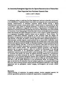
Schematic of the proposed IRCC-URC-GMLST scheme.
can be summarized as follows: 1) We derive the Discrete-input Continuous-output Memoryless Channel (DCMC) [20] capacity formula of GMLST(STBC) schemes and use EXIT charts to design an iteratively decoded near-capacity concatenated IRCC-URC-GMLST scheme. 2) In order to achieve a near-capacity performance, we propose a novel outer IRCC using 36 component codes to accurately match the inner decoder’s EXIT curve. 3) The computational complexity of this concatenated scheme is substantially reduced at the cost of a modest reduction in the maximum achievable rate compared to that of ML detection, owing to the employment of the low-complexity but suboptimum SIC in the GMLST decoder. The rest of this paper is organised as follows. In Section II, a brief description of the serially concatenated and iteratively decoded scheme is presented. Section III specifies the encoding and decoding processes designed for the GMLST system. In Section IV, we derive the DCMC capacity formula and the maximum achievable rate of different GMLST schemes. The EXIT chart aided iterative system design is detailed in Section V, while our simulation results and discussions are provided in Section VI. Finally, we conclude in Section VII. II. S YSTEM OVERVIEW The schematic of the proposed serially concatenated system is illustrated in Fig. 1. At the transmitter side, IRCCs [14], [15] are employed for encoding specifically optimized fractions of the input stream, where each fraction’s code rate was designed for achieving a near-capacity performance with the aid of EXIT charts [13]. Again, a recursive URC was amalgamated with the above-mentioned GMLST in Fig. 1 as the inner code for assisting the non-recursive GMLST scheme in achieving decoding convergence to an infinitesimally low BER at nearcapacity SNRs. The GMLST encoder partitions the long bit stream emanating from the intermediate URC encoder into several substreams and each substream is separately spacetime encoded, as will be detailed in Section III. Two different high-length bit interleavers are introduced between the three component encoders so that the input bits of the URC and GMLST encoders can be rendered independent of each other,
which is one of the required conditions for EXIT charts analysis [13]. At the receiver side, according to Fig. 1, an iterative decoding procedure is operated, which employs three A Posteriori Probability (APP)-based decoders. The received signals are first decoded by the APP-based GMLST decoder in order to produce the a priori Log-Likelihood Ratio (LLR) values L2,a (c2 ) of the coded bits c2 . The URC decoder processes the information forwarded by the GMLST decoder in conjunction with the a priori LLR values L2,a (u2 ) of the information bits u2 in order to generate the a posteriori LLR values L2,p (u2 ) and L2,p (c2 ) of the information bits u2 and the coded bits c2 , respectively. In the scenario when iterations are needed within the amalgamated “URC-GMLST” decoder so as to achieve a near-capacity performance, the a priori LLRs L2,a (c2 ) are subtracted from the a posteriori LLR values L2,p (c2 ) and then they are fed back to the GMLST decoder as the a priori information L3,a (u3 ) through the interleaver π2 . Similarly, the a priori LLR values of the URC decoder are subtracted from the a posteriori LLR values produced by the Maximum Aposteriori Probability (MAP) algorithm [21], for the sake of generating the extrinsic LLR values L2,e (u2 ). Next, the soft bits L1,a (c1 ) are passed to the IRCC decoder in order to compute the a posteriori LLR values L1,p (c1 ) of the IRCC encoded bits c1 . During the last iteration, only the LLR values L1,p (u1 ) of the original information bits u1 are required, which are passed to the hard-decision block in order to estimate the source bits. As seen in Fig. 1, the extrinsic information L1,e (c1 ) is generated by subtracting the a priori information from the a posteriori information, which is fed back to the URC decoder as the a priori information L2,a (u2 ) through the interleaver π1 . For the sake of clarity, in the iterative detection procedure, we define the initial decoding process passing information from the inner decoder to the outer decoder as the first iteration between the two decoders. III. G ENERALIZED M ULTI -L AYER S PACE -T IME C ODE The transmitter and receiver schematics of the GMLST scheme are shown in Fig. 2 and Fig. 3, respectively. The GMLST transmitter shown in Fig. 2 divides the antennas into several groups and each group utilizes an STC encoder. At the receiver side of Fig. 3, we avoid the potentially excessive complexity of jointly detecting all groups. This complexity-
KONG et al.: REDUCED-COMPLEXITY NEAR-CAPACITY DOWNLINK ITERATIVELY DECODED GENERALIZED MULTI-LAYER SPACE-TIME CODING . . .
B1
B
B2
S/P Bq
STC1
Ψ1
STC2
Ψ2
STCq
. . .
Ψq
C.1 . .
C.2 . .
. . .
C.q . .
Nt1 Nt2
Nt
Ntq
Fig. 2. GMLST transmitter schematic using the vector-based temporal interleaver Ψ j .
reduction may be achieved in the spirit of the V-BLAST detection algorithm [5], [22] using the reduced-complexity SIC based detection scheme of [11], where the space-time code of each individual group was processed successively, as will be detailed later in Section III-B. Therefore, it is clearly seen that the GMLST scheme can be viewed as a beneficial amalgam of a V-BLAST and a STC scheme. With the advent of the STC employed, we will show that this GMLST architecture is capable of achieving a higher spatial diversity compared to the conventional V-BLAST scheme. As an added benefit, the overall system’s throughput becomes significantly higher than that of the STC scheme, owing to its BLAST-like layered architecture. A. Encoding Consider now a point-to-point wireless communication link equipped with Nt transmit and Nr receive antennas. When complex-valued M -ary PSK/QAM is employed, the received signal vector of the MIMO system can be written as: y = Hc + n ,
(1)
where y = [y1 , . . . , yNr ]T is an Nr -element vector of the received signals, H is an (Nr × Nt )-element channel matrix, the entries of which are independent and identically complex Gaussian distributed with a zero mean and a variance of 0.5 per dimension, c = [c1 , . . . , cNt ]T is an Nt -element vector of the transmitted signals and n = [n1 , . . . , nNr ]T is an Nr -element noise vector. Each element of n is an Additive White Gaussian Noise (AWGN) process having a zero mean and a variance of N0 /2 per dimension. The GMLST encoding process is illustrated in Fig. 2. We assume that a block of B information bits is input to a serialto-parallel (S/P) converter, which partitions this bit stream into q groups, which we refer to as layers having lengths of B1 , B2 , . . . , Bq , where we have B1 + B2 +, . . . , +Bq = B bits in total. Then, each group of B j bits, for 1 ≤ j ≤ q, is separately encoded in Fig. 2 by a component encoder STC j j associated with Nt number of transmit antennas, where we q j 1 2 have Nt + Nt +, . . . , +Nt = Nt . The resultant (Nt × K)-element j codeword matrix C j of STC j will be transmitted by the Nt transmit antennas of Fig. 2 during K symbol intervals. We refer to the kth column c j,k of C j as the symbol vector generated by group j at time instant k. Following spacetime encoding, the symbol vectors of each group are passed through an independent vector-based temporal interleaver Ψ j . The vector-based temporal interleavers Ψ j represented by the
3
dashed block of Fig. 2 are used for the codewords generated by the different groups, for the sake of eliminating the effects of bursty error propagation among different groups during the decoding iterations [11]. Note that when the STBC is employed as the component space-time code, the vector-based interleavers are not needed at all, because they will destroy the structure of the STBC codeword matrix and would be of no use in eliminating the effects of bursty error propagation, since the different STBC codeword matrices are independent in a specific group. We can rewrite Eq. (1) at time instant k as: yk = H1,k c1,k + H2,k c2,k + ⋅ ⋅ ⋅ + Hq,k cq,k + nk ,
(2)
j
where H j,k denotes the (Nr × Nt )-element subchannel matrix of group j at time instant k. B. Iterative Multistage SIC Detection Again, for the sake of maintaining an affordable computational complexity, a reduced-complexity SIC based detection scheme was proposed in [11] instead of ML detection. For the sake of low complexity, the signals are detected layerby-layer in a multistage manner, instead of high-complexity ML-style joint-detection. In the same spirit of the V-BLAST scheme [23], the decoding order of the SIC-based scheme has a significant effect on the performance of the GMLST system. Similarly to the classic decoding scheme using the optimum decoding method developed in [5], in our per-groupbased optimally ordered decoding scheme, the higher the postdetection SNR of a specific layer, the earlier the layer is chosen to be detected. Without loss of generality, the decoding order in Fig. 3 is assumed to be {1′ , 2′ , . . . , q′ } and we present the SIC-based decoding algorithm as follows. At the first decoding stage ( j = 1), let y1k = yk , for all 1 ≤ k ≤ K. At the jth decoding stage, given that the previous ( j − 1) groups 1′ , 2′ , . . . , ( j − 1)′ have already been decoded and their effects have been cancelled out from the received signals, j the resultant received signal yk for k = 1, . . . , K, which still contains interference imposed by the not-yet-decoded groups ( j + 1)′ , ( j + 2)′ , . . . , q′ , can now be written as j
j
yk = H j′ ,k c j′ ,k + H( j+1)′ ,k c( j+1)′,k + ⋅ ⋅ ⋅ + Hq′ ,k cq′ ,k + nk .
(3)
Then at time instance k, we can find a set of orthonormal column vectors (not necessarily unique) in the null space of [H( j+1)′ ,k , . . . , Hq′ ,k ]T , and amalgamate their transposes into an ′ j′ j [(Nr − Nt + Nt1 + ⋅ ⋅ ⋅ + Nt ) × Nr ]-element nulling matrix Wk 1 based on zero-forcing (ZF). Then, let both sides of Eq. (3) j be left-multiplied by Wk , which suppresses all the interfering signals imposed by the groups ( j + 1)′ to q′ and generates the interference-free equivalent ‘sliced’ signal of group j′ j j j j j j ˜ j′ ,k c j′ ,k + n˜ j . y˜ k = Wk yk = Wk H j′ ,k c j′ ,k + 0 + Wk nk = H k
(4)
˜ j′ ,k is the equivalent channel matrix having We can see that H ′ j′ j′ (Nr − Nt + Nt1 + ⋅ ⋅ ⋅+ Nt )× Nt elements at time instance k for group j′ , which has the same statistical properties as H j′ ,k due j ˜ j′ ,k to the orthonormalizing effect of Wk , i.e., the entries of H are independent and identically complex Gaussian distributed 1 The
j
computation of the nulling matrix Wk is described in the Appendix.
4
IEEE TRANSACTIONS ON WIRELESS COMMUNICATIONS, VOL. 9, NO. 2, FEBRUARY 2010
Nr
... GMLST Decoder La (B1� )
ST Dec
IN
1�
IC La (B2� )
ST Dec 2�
IN IC
H� ˆ1� 1 B ˆ 1� C
H� ˆ2� 2 B ˆ 2� C
. . .
adder
La (B1� )
ST Dec
IC adder La (B2� )
ST Dec 2�
IC
La (Bq� )
ST Dec q �
IC
H� ˆq� q B ˆ q� C
1�
H� ˆ1� 1 B ˆ 1� C
. . .
...
H� ˆq� q B
adder La (Bq� )
ST Dec q �
ˆ q� C
IC
1st iteration
IC
H� ˆ2� 2 B ˆ 2� C
adder
2nd iteration
La (B1� )
ST Dec 1� H1�
adder La (B2� ) IC
ST Dec 2� H2�
ˆ2� B ˆ 2� C
P/S
. . .
adder La (Bq� ) IC
ˆ1� B ˆ 1� C
ST Dec q � Hq�
ˆq� B ˆ q� C
k th iteration
(a) main block diagram
La (Bj � ) ˜ j� y
Demapper
STTC−1 j�
Ψ−1 j�
Ψj �
ˆj � La (Bj � ) B ˜ j� y ˆ j� C
(b) sub-block diagram for the “ST Dec j′ ” component for STTC, where STTC−1 represents soft-input soft-output APP-based STTC j′ decoder and La (B j′ ) correspond to the a priori LLR values of the information bits B j′
ˆj � B
STBC−1 j�
STBCj �
ˆ j� C
(c) sub-block diagram for the “ST Dec j′ ” component for STBC, where STBC−1 represents linear STBC decoder and STBC j′ is the j′ corresponding STBC recoder. The a priori LLR values of the information bits B j′ are not utilized by the corresponding STBC decoder
Fig. 3. GMLST receiver schematic employing iterative multistage SIC detection, where “IN” and “IC” denote the group interference nulling module and the group interference cancellation module respectively.
with a zero mean and a variance of 0.5 per dimension as mentioned in Section III-A. Assuming that perfect interferj ence cancellation is achieved, the resultant noise vector n˜ k also contains independent and identically complex Gaussian distributed entries with mean zero and variance N0 /2 per dimension [10]. Based on Eq. (4), the j′ -layer codeword which is denoted ˆ j′ can be decoded using the corresponding space-time deby C coder of Fig. 3. Prior to moving on to the next decoding stage, interference cancellation is carried out according to Fig. 3 by subtracting the contribution of the just-decoded group j′ from j yk , which results in the ‘partially decontaminated’ received j+1 signal yk j+1
yk
j
= yk − H j′ ,k cˆ j′ ,k ,
1 ≤ k ≤ K,
(5)
ˆ j′ . Then the above procedure where cˆ j′ ,k is the kth column of C of Fig. 3 is repeated for j = j + 1, until all groups are decoded ( j = q). In order to reduce the detrimental effects of error propagation, soft interference cancellation can be invoked, which means that instead of using the hard decisions cˆ j′ ,k in Eq. (5), the expectation value c˜ij′ ,k =
M
∑ xm ⋅ p(cij′,k = xm ∣˜ykj ),
m=1
1 ≤ i ≤ Nt
j′
(6)
is used, where cij′ ,k is the i-th element of vector c j′ ,k and
p(cij′ ,k = xm ∣˜ykj ) is the probability that the M -ary constellation point xm was transmitted, given the equivalent received signal j vector y˜ k . Since soft-values close to the legitimate harddecision-based constellation points are subtracted in Eq. (5) in case of reliable decisions, whereas small values are subtracted in case of unreliable decisions, the effects of potential error propagation are significantly reduced. However, it is clearly seen that this SIC-based decoding scheme fails to achieve the maximum attainable receive diversity, because layer j′ decoded at the jth decoding stage has ′ j′ j′ an antenna diversity order of (Nr − Nt + Nt1 + ⋅ ⋅ ⋅ + Nt ) × Nt . Clearly, the earlier a layer is detected, the lower its diversity order is. In order to maximize the attainable receive diversity gain, the SIC-based iterative decoding scheme of [11] was invoked, which is depicted in Fig. 3. We can see that the first iteration is the same as described above, except that temporal interleaving and deinterleaving should be carried out accordingly, which substantially reduces the effects of burst error propagation among groups. In the subsequent iterations, since all groups have already been decoded, the interference nulling (IN) stage of Eq. (4) and Fig. 3 is no longer needed, which results in a theoretical receive diversity order of Nr for each group. Each iteration consists of q layers and each STC-protected layer is processed successively, in the same order as during the first iteration. After a number of iterations, the maximum attainable receive diversity order of Nr may be achieved for all layers, when the residual error propagation
KONG et al.: REDUCED-COMPLEXITY NEAR-CAPACITY DOWNLINK ITERATIVELY DECODED GENERALIZED MULTI-LAYER SPACE-TIME CODING . . .
GMLST Decoder Ψ−1 1 Ψ1
Nr
. . .
ML
Ψ−1 2 Ψ2
Demapper
.. .
Ψ−1 q Ψq
STTC−1 1 STTC−1 2
.. .
STTC−1 q
considered quasi-static over this period. Based on Eq. (1), the signal received during L symbol periods can be written as:
ˆ1 B La (B1 )
Y = HC + N ,
ˆ2 B
La (B2 )
5
P/S
ˆq B La (Bq )
Fig. 4. Iterative ML detection of the GMLST(STTC) scheme, where Ψ j is the corresponding temporal interleaver, STTC−1 j represents j-layer soft-input soft-output APP-based space-time decoder and La (B j ) correspond to the a priori LLR values of the information bits B j .
among different groups becomes negligible. Compared to ML detection, this iterative decoding scheme is capable of approaching the same receive diversity order, despite imposing only a fraction of the computational complexity of ML-style joint detection. C. Iterative ML Detection for GMLST(STTC) For comparison, we also present a significantly more complex iterative ML detection scheme in Fig. 4 designed for GMLST schemes using STTC [8] as the component STCs, which we refer to as the GMLST(STTC) arrangement. The iterative ML detection procedure is shown in Fig. 4. Firstly, the Nt transmitted M -ary symbols are jointly detected as a combined [Nt × log2 M ]-bit symbol by an ML demapper. Then, the probability vector of each [Nt × log2 M ]-bit symbol is converted to q number of probability vectors corresponding j to the q number of [Nt × log2 M ]-bit symbols of the different layers. The resultant probability vectors are then fed to the component STTC decoders. An iterative detection gain can be attained, since the EXIT curve of the ML demapper is a sloping line, although this is not explicitly shown here owing to space limitations. However, it is not guaranteed that the DCMC capacity, as detailed later in Section IV, can be achieved with the aid of iterative ML detection, because the maximum achievable rate of the iterative ML detection scheme is dependent on the EXIT curve shapes of the various spacetime trellis codes. IV. C APACITY AND M AXIMUM ACHIEVABLE R ATE In the context of discrete-amplitude QAM [20] and PSK [20] modulation, a Discrete-input Continuous-output Memoryless Channel (DCMC) is encountered. In order to design a near-capacity coding scheme, in this section we derive the DCMC capacity formula for GMLST(STBC), which refers to the GMLST schemes using STBC [6], [7] as the component STCs. Additionally, the bandwidth efficiency of various SIC and ML based GMLST(STTC) schemes is derived for transmission over the DCMC based on the properties of EXIT charts [24]. A. DCMC Capacity of GMLST(STBC) A specific GMLST scheme using an identical STBC to the component STBCs is designed for encoding over L transmission symbols, assuming that the channel’s envelope may be
(7)
where Y = [y1 , . . . , yL ] ∈ ℂNr ×L is the sampled received signal matrix, H ∈ ℂNr ×Nt is the quasi-static channel matrix, which is constant over L symbol periods, C = [c1 , . . . , cL ] ∈ ℂNt ×L is the GMLST(STBC) transmitted signal matrix and N = [n1 , . . . , nL ] ∈ ℂNr ×L represents the additive white Gaussian noise matrix. In this contribution, we only consider STBCs having squareshaped codeword matrices [6], [25]–[27] as the component STBCs of the GMLST schemes, where we have L = Nt /q. For example, when Alamouti’s G2 space-time scheme [6] is used as the component STBC, the GMLST(STBC) codeword matrix is as follows: )T ( c1,1 c1,2 . . . c j,1 c j,2 . . . cq,1 cq,2 , C= −c¯1,2 c¯1,1 . . . −c¯j,2 c¯j,1 . . . −c¯q,2 c¯q,1 (8) where the columns represent L = 2 different time slots, while the rows )T represent qL different transmit antennas, and ( c j,1 c j,2 is the j-layer STBC codeword matrix. Hence, −c¯j,2 c¯j,1 when complex-valued M -ary PSK/QAM is employed in a GMLST(STBC) scheme, we have a total of M = M qL number of possible GMLST(STBC) codeword matrix combinations for L consecutive symbol periods. Based on Eq. (7), the conditional probability of receiving a signal matrix Y, given that an M-ary GMLST(STBC) codeword matrix Cm , m ∈ {1, . . . , M}, was transmitted over uncorrelated flat Rayleigh fading channels is determined by the Probability Density Function (PDF) of the noise, yielding: ( ) −∥Y − HCm∥2 1 p(Y∣Cm ) = exp , (9) N0 (πN0 )LNr ( ) Nt m ∣2 L Nr −∣yr,k − ∑t=1 hr,t ct,k 1 exp . = ∏∏ N0 k=1 r=1 πN0 The channel capacity per symbol period evaluated for the GMLST(STBC) scheme when using complex-valued M -ary PSK/QAM for transmission over the DCMC can be shown to be: GMLST(STBC) CDCMC
= (
⋅ log2
M 1 max ∑ L p(C1 )...p(CM ) m=1
∫ Y
p(Y∣Cm ) n n ∑M n=1 p(Y∣C )p(C )
p(Y∣Cm )p(Cm ) ) dY, (10)
where the right hand side of Eq. (10) is maximized, when we have p(Cm ) = 1/M for m ∈ {1, . . . , M}. Hence, Eq. (10) can be simplified to: GMLST(STBC) CDCMC =
log2 (M) − L[
] � M � m 1 M ∑ E log2 ∑ exp(Ψm,n ) �� C , (11) ML m=1 n=1
where E[A∣Cm ] is the expectation of A conditioned on Cm and the expectation in Eq. (11) is taken over H and N, while Ψm,n
6
IEEE TRANSACTIONS ON WIRELESS COMMUNICATIONS, VOL. 9, NO. 2, FEBRUARY 2010
mimo-glst-4x4-4qam.gle
6
CCMC4x4 DCMC4x4-4QAM DCMC4x4-4QAM-GMLST(STBC-G2) GMLST(STBC-G2)-4QAM, 2 Soft SIC GMLST(STBC-G2)-4QAM, 2 Hard SIC GMLST(STBC-G2)-4QAM, 1 Hard SIC GMLST(STTC-16)-4QAM, ML w/ 3 Iter GMLST(STTC-16)-4QAM, ML w/o Iter GMLST(STTC-16)-4QAM, 3 Soft SIC GMLST(STTC-16)-4QAM, 3 Hard SIC GMLST(STTC-16)-4QAM, 1 Hard SIC
5
(bit/s/Hz)
4
3 Nt=4, Nr=4, =2 bit/s/Hz Eb/N0=-6.20dB:CCMC4x4 Eb/N0=-6.10dB:DCMC4x4-4QAM Eb/N0=-5.40dB:DCMC4x4-4QAM-GMLST(STBC-G2) Eb/N0=-5.00dB:GMLST(STBC-G2)-4QAM, 2 Soft SIC Eb/N0=-4.70dB:GMLST(STBC-G2)-4QAM, 2 Hard SIC Eb/N0=-3.40dB:GMLST(STBC-G2)-4QAM, 1 Hard SIC Eb/N0=-6.05dB:GMLST(STTC-16)-4QAM, ML w/ 3 Iter Eb/N0=-5.70dB:GMLST(STTC-16)-4QAM, ML w/o Iter Eb/N0=-5.90dB:GMLST(STTC-16)-4QAM, 3 Soft SIC Eb/N0=-5.70dB:GMLST(STTC-16)-4QAM, 3 Hard SIC Eb/N0=-3.80dB:GMLST(STTC-16)-4QAM, 1 Hard SIC
2
1
0
-8
-7
-6
-5
-4
-3
Eb/N0 [dB]
-2
-1
0
1
2
Fig. 5. The capacity and maximum achievable rate of various SIC and ML based GMLST schemes, when communicating over uncorrelated flat Rayleigh fading channels employing Nt = 4 transmit antennas and Nr = 4 receive antennas.
is given by: Ψm,n
=
−∥H(Cm − Cn ) + N∥2 + ∥N∥2 . N0
(12)
Based on the DCMC capacity formula of Eq. (11) we can compute the capacity of any GMLST(STBC) scheme by substituting the corresponding GMLST(STBC) codeword matrix C ∈ ℂNt ×L into Eq. (12). The resultant bandwidth efficiency is computed by normalising the channel capacity given by Eq. (11), with respect to the product of the bandwidth W and the signalling period T : C [bit/s/Hz] , (13) WT where W T = 1 for PSK/QAM schemes, when assuming zero Nyquist excess bandwidth. The bandwidth efficiency, η, is typically plotted against the SNR per bit given by: Eb /N0 = SNR/η. For simplicity, we will refer to η as the capacity. η=
B. Maximum Achievable Rate Based on EXIT Charts The concept of EXIT charts was first proposed in [12]. It was then stated in [15], [24] that the maximum achievable bandwidth efficiency/rate of the system is equal to the area under the EXIT curve of the inner code, provided that the channel’s input is independently and uniformly distributed, assuming furthermore that the inner code rate is 1 and that the MAP decoding algorithm is used. This area property of the EXIT charts may be exploited by considering Fig. 2 of [24]. Explicitly, the area under the EXIT curve of the inner code quantifies the capacity of the communication channel (the upper a priori Channel 1 in Fig. 2 of [24]), when the communication channel’s input is independently and uniformly distributed, while the a priori channel (the lower a priori Channel 2 in Fig. 2 of [24]) is modeled by a Binary Erasure Channel (BEC). This area property was shown to be valid for arbitrary inner codes and communication channels,
provided that the a priori Channel 2 is a BEC. Furthermore, there is experimental evidence that the area property of EXIT charts is also valid when the a priori Channel 2 is modeled by an AWGN channel, as it was originally done in [13]. Based on the area property of EXIT charts, the maximum achievable rate curves of various SIC and ML based GMLST schemes are shown in Fig. 5 together with the DCMC capacity curves of the multiplexing-based MIMO scheme, which employed a ML detector. The capacity curve of the unrestricted Continuous-input Continuous-output Memoryless Channel (CCMC) [4], [20] is also depicted in Fig. 5 for comparison. In this contribution, we consider the scenario when Nt = 4 transmit and Nr = 4 receive antennas are used, where Nt1 = Nt2 = 2. For simplicity, the component STCs utilized for all groups are assumed to be identical. Specifically, we use STBC-G2 [6] and 16-state based STTC-16 [8, Fig. 5] as the component STCs of the GMLST schemes, respectively. As shown in Fig. 5, the DCMC capacity of the multiplexingbased MIMO scheme employing 4QAM (DCMC4×4 -4QAM) is higher than that of all the GMLST schemes and may be regarded as the tight capacity upper bound of the (4 × 4)element 4QAM MIMO systems. On the other hand, the DCMC capacity curve of the GMLST scheme using STBCG2 is plotted against Eb /N0 according to Eq. (11), which is indicated by the label DCMC4×4 -4QAM-GMLST(STBC-G2) in Fig. 5. Note that the DCMC4×4 -4QAM-GMLST(STBC-G2) capacity curve is below that of the ML-based GMLST(STTC16) scheme using three iterations. This is due to the loss of temporal diversity within the STBC-G2 orthogonal code of each group [4]. It is also seen in Fig. 5 that when invoking two SIC operations in the GMLST(STBC-G2) scheme, the maximum achievable rate curve approaches the DCMC4×4 4QAM-GMLST(STBC-G2) rate curve, since the maximum attainable receive diversity has been approached. However, no substantial further improvements are attained after two SICs, since the remaining inter-group interference propagating
KONG et al.: REDUCED-COMPLEXITY NEAR-CAPACITY DOWNLINK ITERATIVELY DECODED GENERALIZED MULTI-LAYER SPACE-TIME CODING . . .
V. EXIT C HART A IDED S YSTEM D ESIGN AND A NALYSIS The main objective of employing EXIT charts [13] is to analyse the convergence behaviour of iterative decoders by examining the evolution of the input/output mutual information exchange between the inner and outer decoders during the consecutive iterations. As mentioned in Section IV, the area under the EXIT curve of the inner decoder is approximately equal to the channel capacity, when the channel’s input is independently and uniformly distributed. Similarly, the area under the EXIT curve of the outer code is approximately equal to (1-R), where R is the outer code rate. Furthermore, our experimental results show that an intermediate URC changes only the shape, but not the area under the EXIT curve of the inner code. We assume that the normalised area under the EXIT curve of the inner decoder is represented by AE throughout this paper. A narrow, but marginally open EXITtunnel in an EXIT chart indicates the possibility of achieving a near-capacity performance. Therefore, we invoke IRCCs for the sake of appropriately shaping the EXIT curves by minimizing the area in the EXIT-tunnel with the aid of the optimization algorithm of [14]. The original IRCC constituted by a set of P = 17 subcodes was constructed in [15] from a systematic, rate-1/2, memory-4 mother code defined by the generator polynomial (1, g1 /g0 ), where g0 = 1 + D + D4 is the feedback polynomial and g1 = 1 + D2 + D3 + D4 is the feedforward one. Higher code rates may be obtained by puncturing, while lower rates are created by adding more generators and by puncturing under the constraint of maximizing the achievable free distance. In the proposed system the two additional generators are
1.0 0.9
0.7 0.6
. .. . . 0.4 . . . . .. 0.3 . . .. 0.2 .. .. . . 0.1 . .. . . . 0.0 0.5
IE
.. ... .. ... .. .. . .. .. . exitchart-glst-stbc-g2-urc.gle
Decoding trajectory for GMLST(STBC-G2)Hard-2-URC Eb/N0 = -4.2 dB
0.8
.
. ..
.
Nt=4, Nr=4, =2 bit/s/Hz GMLST(STBC-G2)Hard-2-URC: Eb/N0 = -4.2 dB (AE=0.53) GMLST(STBC-G2)Hard-2: Eb/N0 = -4.7 dB (AE=0.50) IRCC : R=0.5 (AE=0.50)
0.0 0.1 0.2 0.3 0.4 0.5 0.6 0.7 0.8 0.9 1.0
IA
Fig. 6. The EXIT chart curves for the GMLST(STBC-G2)-URC, 17component IRCC having weighting coefficients [α1 ,⋅⋅⋅ ,α17 ] = [0, 0, 0.0131465, 0.01553, 0, 0, 0.48839, 0.215005, 0, 0, 0, 0, 0.198844, 0, 0, 0, 0.0691192] and 17 original IRCC subcodes, when communicating over uncorrelated flat Rayleigh fading channels using Nt = 4 and Nr = 4. The notation GMLST(STBC-G2)Hard-2 indicates 2 hard SIC iterations in GMLST decoder and no iteration is needed between the GMLST(STBC-G2) and URC decoders, since the EXIT curve of the GMLST(STBC-G2) detector is a horizontal line.
1.0 0.9
.. ... .. ... .. .. . .. .. . exitchart-glst-stbc-g2-urc.gle
Decoding trajectory for GMLST(STBC-G2)Soft-2-URC Eb/N0 = -4.5 dB
0.8 0.7 0.6
. .. . . . 0.4 . . .. . 0.3 . .. . 0.2 .. .. . . 0.1 . . . .. 0.0 . 0.5
IE
across the groups is independently distributed across K/2 consecutive G2 codeword block periods during K symbol intervals and hence cannot be eliminated by SIC operations. By contrast, for the GMLST(STTC-16) scheme of Fig. 5, the maximum achievable rate improves steadily for three SIC operations, although the maximum attainable receive diversity has already been achieved during the second iteration. This is due to the strong error-correcting capability of the STTC associated with temporal vector-based interleavers. Observe in Fig. 5 that beyond three SICs, the additional improvements remain marginal. For further improvements, soft interference cancellation can be invoked for both the GMLST(STBC) and GMLST(STTC) schemes, which is explicitly demonstrated in Fig. 5 as well. Since no iterations can be carried out between the SIC-based demodulator and the STTC decoder when using SIC-based detection, some mutual information or throughput loss occurs, which cannot be recovered. For comparison, the maximum achievable rate of the ML based iterative detection scheme of GMLST(STTC-16) is also quantified in Fig. 5. The number of iterations between the ML demapper and the GMLST component STTC decoders was fixed to three, which is the same as the number of SIC iterations. Hence, both schemes invoke the same number of STTC decoder operations, but the ML demapper exhibits a higher complexity than the SIC operation. As shown in Fig. 5, the ML-based scheme provides a higher maximum achievable rate than that of the SIC-based arrangement.
7
. ..
..
Nt=4, Nr=4, =2 bit/s/Hz GMLST(STBC-G2)Soft-2-URC: Eb/N0 = -4.5 dB (AE=0.53) GMLST(STBC-G2)Soft-2: Eb/N0 = -5.0 dB (AE=0.50) IRCC : R=0.5 (AE=0.50)
0.0 0.1 0.2 0.3 0.4 0.5 0.6 0.7 0.8 0.9 1.0
IA
Fig. 7. The EXIT chart curves for the GMLST(STBC-G2)-URC, 17component IRCC having weighting coefficients [α1 ,⋅⋅⋅ ,α17 ] = [0, 0, 0.0131465, 0.01553, 0, 0, 0.48839, 0.215005, 0, 0, 0, 0, 0.198844, 0, 0, 0, 0.0691192] and 17 original IRCC subcodes, when communicating over uncorrelated flat Rayleigh fading channels using Nt = 4 and Nr = 4. The notation GMLST(STBC-G2)Soft-2 indicates 2 soft SIC iterations in GMLST decoder and no iteration is needed between the GMLST(STBC-G2) and URC decoders, since the EXIT curve of the GMLST(STBC-G2) detector is a horizontal line.
IEEE TRANSACTIONS ON WIRELESS COMMUNICATIONS, VOL. 9, NO. 2, FEBRUARY 2010
P
P
i=1
i=1
1 = ∑ αi , R = ∑ αi ri , and αi ∈ [0, 1], ∀i.
(14)
In this paper, we consider an average coding rate of R = 0.5 for the outer IRCC code. Hence the effective throughput is 2 The optimum selection was found by computer search using the iterative procedure of the optimization algorithm [14].
1.0
.. ... . .. . .. .. . . .. exitchart-glst-stbc-g2-urc.gle
Decoding trajectory for GMLST(STBC-G2)ML-URC2 Eb/N0 = -5.0 dB
0.9 0.8 0.7 0.6
.. . . 0.4 . .. . 0.3 .. . .. 0.2 .. .. . . 0.1 . .. . . . 0.0 0.5
IE
g2 = 1 + D + D2 + D4 and g3 = 1 + D + D3 + D4 . The resultant P = 17 subcodes have coding rates spanning 0.1, 0.15, 0.2, . . ., to 0.9. The EXIT functions of these 17 original subcodes are shown in Figs. 9-11, indicated by the dotted lines. Observe in Figs. 911 that the original memory-4 IRCC exhibits a near-horizontal portion in the EXIT chart, which is typical of strong CCs having a memory of 4 associated with 16 trellis states. As discussed in [14], [15], the EXIT function of an IRCC can be obtained by superimposing those of its subcodes. More specifically, the EXIT function of the target IRCC is the weighted superposition of the EXIT functions of its subcodes. Hence, a careful selection of the weighting coefficients2 could produce an outer code EXIT curve that closely matches the EXIT curve shape of the inner code. When the area between the two EXIT curves is minimized, decoding convergence to an infinitesimally low BER would be achieved at the lowest possible SNR. On the other hand, in order to match the shape of the inner codes’ EXIT curves more accurately, the shape of the outer codes’ EXIT functions can be adjusted in a way, which allows us to match a more diverse-shaped set of inner codes’ EXIT functions. Hence we introduce a more diverse range of EXIT functions, particularly near the diagonal of the EXIT chart. This can be achieved by invoking weaker codes having a lower memory. Accordingly, memory-1 CCs are incorporated into the original IRCC scheme, which have a simple two-state trellis diagram. The generator polynomial of this rate-1/2 memory-1 mother code is defined by (1, g1 /g0 ), where g0 = D and g1 = 1. For a lower code rate, an extra output generator polynomial, namely g2 is used, where g2 = g1 . For a higher code rate, the puncturing pattern of the original memory-4 IRCC is employed [15]. This way we generate 10 additional EXIT functions as shown by the dashed lines in Figs. 9-11, spanning the range of [0.45, 0.9] with a stepsize of 0.05. Furthermore, a repetition code is a simple memoryless code, which consists of only two codewords, namely the all-zero and the all-one word. Since it has no memory, the EXIT functions of such repetition codes are diagonally-shaped. Hence, we also incorporate 9 different-rate repetition codes in the novel IRCC scheme, as indicated by the solid lines in Figs. 9-11 and spanning the code-rate range of [0.1, 0.5] with the rate-stepsize of 0.05. Similarly to [15], each of these P = 36 subcodes encodes a specific fraction of the information bit stream according to a specific weighting coefficient αi , where i = 1, 2, . . . , 36. More specifically, assume that there are N number of encoded bits, where each subcode i encodes a fraction of αi ri N information bits and generates αi N encoded bits using a coding rate of ri . As for the P number of subcodes, given the target overall average code rate of R ∈ [0, 1], the weighting coefficients αi must satisfy:
. ..
..
. ..
..
Nt=4, Nr=4, =2 bit/s/Hz GMLST(STBC-G2)ML-URC2: Eb/N0 = -5.0 dB (AE=0.52) GMLST(STBC-G2)ML: Eb/N0 = -5.4 dB (AE=0.50) IRCC : R=0.5 (AE=0.50)
0.0 0.1 0.2 0.3 0.4 0.5 0.6 0.7 0.8 0.9 1.0
IA
Fig. 8. The EXIT chart curves for the GMLST(STBC-G2)-URC, 17component IRCC having weighting coefficients [α1 ,⋅⋅⋅ ,α17 ] = [0, 0, 0, 0, 0, 0.327442, 0.186505, 0.113412, 0, 0.0885527, 0, 0.0781214, 0.0962527, 0.0114205, 0.0346015, 0.0136955, 0.0500168] and 17 original IRCC subcodes, when communicating over uncorrelated flat Rayleigh fading channels using Nt = 4 and Nr = 4. The notation GMLST(STBC-G2)ML indicates the ML decoder for the GMLST(STBC-G2) scheme and the subscript of URC denotes the number of iterations between the GMLST(STBC-G2)ML and URC decoders.
1.0 0.9 0.8 0.7 0.6 0.5 0.4 0.3 0.2 0.1
.. . .
exitchart-glst-sttc16-urc.gle
Decoding trajectory for GMLST(STTC-16)Hard-3-URC6 Eb/N0 = -5.0 dB
IE
8
..
..
. ..
..
.. .. . .. .. . .. .. . .. .. . .. .. . . .. . . .. .
.
. ..
..
Nt=4, Nr=4, =2 bit/s/Hz GMLST(STTC-16)Hard-3-URC6: Eb/N0 = -5.00 dB (AE=0.56) GMLST(STTC-16)Hard-3: Eb/N0 = -5.70 dB (AE=0.50) IRCC : R=0.5 (AE=0.50)
0.0 0.0 0.1 0.2 0.3 0.4 0.5 0.6 0.7 0.8 0.9 1.0
IA
Fig. 9. The EXIT chart curves for the GMLST(STTC-16)Hard -URC and 36-component IRCC having weighting coefficients [α1 ,⋅⋅⋅ ,α36 ] = [0, 0, 0, 0, 0, 0, 0, 0, 0, 0, 0.0238076, 0.0654278, 0.0108539, 0, 0.0736835, 0.0251597, 0.124231, 0.0829128, 0, 0.140577, 0.0983615, 0.134327, 0.109642, 0, 0, 0, 0, 0, 0, 0, 0, 0, 0, 0, 0.00875876, 0.102257] and 36 IRCC subcodes, when communicating over uncorrelated flat Rayleigh fading channels using Nt = 4 and Nr = 4. The notation GMLST(STTC-16)Hard-3 indicates 3 hard SIC iterations in GMLST decoder, and the subscript of URC denotes the number of iterations between the GMLST(STTC-16)Hard and URC decoders.
KONG et al.: REDUCED-COMPLEXITY NEAR-CAPACITY DOWNLINK ITERATIVELY DECODED GENERALIZED MULTI-LAYER SPACE-TIME CODING . . .
VI. S IMULATION R ESULTS AND D ISCUSSIONS As we can see from Figs. 9 and 10, the Monte-Carlo simulation based decoding trajectory of the IRCC-URCGMLST(STTC-16) schemes using SIC detection within the GMLST(STTC-16) decoder has a slight mismatch with their EXIT curves. This is due to the trellis structure of STTCs, which results in correlated non-zero error propagation between the different layers in the process of SIC operation. By contrast, the decoding trajectory of the IRCC-URCGMLST(STBC-G2) scheme of Fig. 6 and 7 using hard and soft SIC accurately matches both the inner and the outer EXIT curves owing to the uncorrelated non-zero error propagation. For comparison, Fig. 8 presents the decoding trajectory of the IRCC-URC-GMLST(STBC-G2) scheme using an ML decoder. On the other hand, the decoding trajectory of the IRCCURC-GMLST(STTC-16) scheme employing ML detection is presented in Fig. 11. Again, we use three iterations between
1.0 0.9 0.8 0.7 0.6
IE
0.5 0.4 0.3 0.2 0.1
. ..
..
exitchart-glst-sttc16-urc.gle
Decoding trajectory for GMLST(STTC-16)Soft-3-URC6 Eb/N0 = -5.1 dB
..
..
. ..
..
.. .. . .. .. . .. .. . .. .. . . .. . .. .. . . .. .
. ..
..
Nt=4, Nr=4, =2 bit/s/Hz GMLST(STTC-16)Soft-3-URC6: Eb/N0 = -5.10 dB (AE=0.57) GMLST(STTC-16)Soft-3: Eb/N0 = -5.90 dB (AE=0.50) IRCC : R=0.5 (AE=0.50)
0.0 0.0 0.1 0.2 0.3 0.4 0.5 0.6 0.7 0.8 0.9 1.0
IA
Fig. 10. The EXIT chart curves for the GMLST(STTC-16)Soft -URC and 36component IRCC having weighting coefficients [α1 ,⋅⋅⋅ ,α36 ] = [0, 0, 0, 0, 0, 0, 0, 0, 0, 0, 0.0238076, 0.0654278, 0.0108539, 0, 0.0736835, 0.0251597, 0.124231, 0.0829128, 0, 0.140577, 0.0983615, 0.134327, 0.109642, 0, 0, 0, 0, 0, 0, 0, 0, 0, 0, 0, 0.00875876, 0.102257] and 36 IRCC subcodes, when communicating over uncorrelated flat Rayleigh fading channels using Nt = 4 and Nr = 4. The notation GMLST(STTC-16)Soft-3 indicates 3 soft SIC iterations in GMLST decoder, and the subscript of URC denotes the number of iterations between the GMLST(STTC-16)Soft and URC decoders.
1.0 0.9 0.8 0.7 0.6 0.5 0.4 0.3 0.2 0.1
. ..
..
exitchart-glst-sttc16-urc.gle
Decoding trajectory for GMLST(STTC-16)ML-3-URC6 Eb/N0 = -5.3 dB
IE
2 × R log2 4 = 2 bit/s/Hz, when 4QAM is employed by the above-mentioned two-layer GMLST schemes. The maximum achievable rates of different GMLST schemes computed according to the properties of EXIT charts [15], [24] at a throughput of η = 2 bit/s/Hz are depicted in Fig. 5. The exchange of extrinsic information in the schematic of Fig. 1 is visualised by plotting the EXIT characteristics of the inner amalgamated “URC-GMLST” decoder and the specific optimized outer IRCC decoder in Figs. 6-11. Note that for GMLST(STBC-G2) scheme of Figs. 6 and 7, a near-capacity performance may be achieved without extrinsic information exchange using decoding iterations between the URC decoder and the GMLST(STBC-G2) decoder, since the EXIT curve of the SIC-based GMLST(STBC-G2) decoder is a horizontal line. As seen in Figs. 6, 7 and 8, when we employ the 17 original outer subcodes of [15] in our IRCC design, the outer IRCC is capable of accurately matching the EXIT curve of the inner amalgamated “URC-GMLST” decoder with the aid of the matching algorithm of [14]. On the other hand, observe in Figs. 9, 10 and 11, for the GMLST(STTC16) scheme that the EXIT curve of the GMLST(STTC-16) decoder is a slanted line, hence extrinsic information exchange using decoding iterations between the URC decoder and the GMLST(STTC-16) decoder is needed in order to achieve a near-capacity performance. When there is no iteration between the URC decoder and the GMLST(STTC-16) decoder, the EXIT curve shape of the URC decoder depends on the IE value of the GMLST(STTC-16) decoder observed in Figs. 9, 10 and 11 at IA = 0. Hence, the URC-GMLST(STTC-16) scheme requires a higher Eb /N0 value in order to maintain a normalised area of AE = 0.5, as shown in Figs. 9, 10 and 11. In other words, a certain mutual information i.e. throughput loss will occur, if there is no iteration between the URC decoder and the GMLST(STTC-16) decoder. Furthermore, due to the “S”-shape of the inner amalgamated “URC-GMLST” decoder’s EXIT curve, the original IRCC using 17 subcodes cannot match it accurately [28, Figs. 7 and 8]. As a benefit, the proposed 36-component IRCC has a more diverse range of EXIT function shapes, hence it is capable of providing more accurately matching EXIT curves to fit the inner amalgamated “URC-GMLST” decoders, as depicted in Figs. 9, 10 and 11.
9
..
..
. ..
..
.. .. . .. .. . .. .. . .. .. . .. .. . .. .. . .. .
. ..
..
Nt=4, Nr=4, =2 bit/s/Hz GMLST(STTC-16)ML-3-URC6: Eb/N0 = -5.30 dB (AE=0.53) GMLST(STTC-16)ML-3: Eb/N0 = -6.05 dB (AE=0.50) IRCC : R=0.5 (AE=0.50)
0.0 0.0 0.1 0.2 0.3 0.4 0.5 0.6 0.7 0.8 0.9 1.0
IA
Fig. 11. The EXIT chart curves for the GMLST(STTC-16)ML -URC and 36component IRCC having weighting coefficients [α1 ,⋅⋅⋅ ,α36 ] = [0, 0, 0, 0, 0, 0, 0, 0, 0, 0, 0.0238076, 0.0654278, 0.0108539, 0, 0.0736835, 0.0251597, 0.124231, 0.0829128, 0, 0.140577, 0.0983615, 0.134327, 0.109642, 0, 0, 0, 0, 0, 0, 0, 0, 0, 0, 0, 0.00875876, 0.102257] and 36 IRCC subcodes, when communicating over uncorrelated flat Rayleigh fading channels using Nt = 4 and Nr = 4. The notation GMLST(STTC-16)ML-3 indicates 3 iterations between ML demapper and GMLST component decoders, and the subscript of URC denotes the number of iterations between the GMLST(STTC-16)ML and URC decoders.
10
IEEE TRANSACTIONS ON WIRELESS COMMUNICATIONS, VOL. 9, NO. 2, FEBRUARY 2010
1
10
10
... . .
-1
0.9dB
-2
1.4dB 1.2dB 1.0dB
10
-5
10
-6
-7
-6
GMLST(G2) DCMC Capacity
-4
DCMC4x4-4QAM Capacity
10
.
-3 GMLST(STTC) Max Achievable Rate
BER
10
ber-ircc-urc-glst.gle
GMLST(STBC-G2)Hard-1 GMLST(STBC-G2)Hard-2 GMLST(STBC-G2)Soft-2 GMLST(STBC-G2)ML GMLST(STTC-16)Hard-1 GMLST(STTC-16)Hard-3 GMLST(STTC-16)Soft-3 GMLST(STTC-16)ML-3
. . -5
. -4
GMLST(STBC-G2)Hard-2-URC-IRCC, 16 iter. GMLST(STBC-G2)Soft-2-URC-IRCC, 16 iter. GMLST(STBC-G2)ML-URC-IRCC, 16 iter. GMLST(STTC-16)Hard-3-URC-IRCC, 16 iter. GMLST(STTC-16)Soft-3-URC-IRCC, 16 iter. GMLST(STTC-16)ML-3-URC-IRCC, 16 iter. GMLST(STBC-G2)Hard-2-URC-IRCC, 20 iter. GMLST(STBC-G2)Soft-2-URC-IRCC, 20 iter. GMLST(STBC-G2)ML-URC-IRCC, 20 iter. GMLST(STTC-16)Hard-3-URC-IRCC, 20 iter. GMLST(STTC-16)Soft-3-URC-IRCC, 20 iter. GMLST(STTC-16)ML-3-URC-IRCC, 20 iter.
-3
-2
Eb/N0 [dB]
-1
0
1
2
3
Fig. 12. The BER performance comparison of the IRCC-URC-GMLST schemes and of the stand-alone GMLST schemes with various SIC and ML based GMLST decoders.
the ML demapper and GMLST component decoders so that the number of STTC decoder operations invoked remains the same as that of the scheme employing three SIC iterations. Since there is no error propagation in the ML-based scheme, the decoding trajectory of the ML-based scheme closely matches its EXIT curve. However, the error propagation was avoided in the ML-based scheme at the price of a higher complexity. Fig. 12 presents the BER performance of both the nearcapacity IRCC-URC-GMLST and of the stand-alone GMLST schemes employing various space-time codes combined with SIC and ML detection. It is observed that for three SIC operations, the performance of the GMLST(STTC-16) scheme significantly improves due to the attainment of the maximum achievable receive diversity, whereas the soft-SIC based scheme approaches the performance of the ML-detected GMLST(STTC-16) scheme more closely since the residual error propagation is further mitigated. On the other hand as seen in Fig. 12, the GMLST(STBC-G2) scheme using two SIC operations exhibits a 1.6 dB gain over a single hard SIC, but no more improvements are attained beyond two SIC operations, since the residual interference propagating among groups is independently distributed across K/2 consecutive G2 codeword block periods during K symbol intervals and cannot be eliminated by SIC operations. Observe in Fig. 12 that the throughput of the stand-alone GMLST schemes is far from the corresponding DCMC capacity. For the concatenated systems, it is clearly shown in Fig. 12 that the IRCCURC-GMLST(STBC-G2) scheme is capable of performing within 0.9 dB of the corresponding DCMC capacity of the GMLST(STBC-G2) scheme, when soft SIC is employed. On the other hand, observe in Figs. 9 and 10 that the IRCC-URCGMLST(STTC-16) scheme exhibits a mismatch between the decoding trajectory and the EXIT curve, but performs closer to the DCMC4×4 -4QAM capacity as shown in Fig. 12 at the price of a significantly higher complexity than that of the IRCC-
URC-GMLST(STBC-G2) scheme. The BER performance of the most complex ML-detected IRCC-URC-GMLST(STTC16) scheme is also depicted in Fig. 12, where we can see a 0.4 dB gain over the soft SIC based scheme. However, the complexity of the ML-based scheme is unaffordable, especially when the number of GMLST layers is high. VII. C ONCLUSIONS In this contribution, we have proposed a low-complexity SIC-based iteratively decoded IRCC-URC-GMLST scheme for achieving a near-capacity performance with the aid of EXIT chart analysis. According to the simulation results, we found that the iterative IRCC-URC-GMLST scheme using SIC detection strikes an attractive trade-off between the complexity imposed and the effective throughput achieved. In conclusion, we summarize our design procedure as follows: 1) Derive the DCMC capacity formula of GMLST(STBC) schemes and quantify the maximum achievable rates of the GMLST schemes using 16-state STTCs with the aid of EXIT charts. 2) Generate the EXIT curve of the inner decoder, which is constituted here by the GMLST decoder and URC decoder. 3) Design an IRCC outer code to match the EXIT curve of the inner code and hence to approach the capacity determined for the high-complexity, but optimum ML detector. 4) Reduce the complexity imposed by the ML detector by using the lower-complexity SIC detector, while avoiding any substantial performance degradation by redesigning the IRCC scheme with more component codes, which hence matches the EXIT curve of the SIC inner decoder more accurately. 5) This design procedure is generically applicable, regardless of the specific choice of the inner and outer
KONG et al.: REDUCED-COMPLEXITY NEAR-CAPACITY DOWNLINK ITERATIVELY DECODED GENERALIZED MULTI-LAYER SPACE-TIME CODING . . .
decoder components, as exemplified by other detectors, such as Sphere Detector (SD), Markov chain Monte Carlo (MCMC) detector as well as by other outer codes, such as an irregular low-density parity-check (LDPC) code, etc. A PPENDIX T HE NULLING MATRIX
= 0,
(15)
which can be reformulated in the transpose notation as: j
[H( j+1)′ ,k , . . . , Hq′ ,k ]T ⋅ [Wk ]T = 0.
(16)
Since the null space of a matrix A is the set of all vectors v, which solves the equation Av = 0, where v is also referred to as the kernel of A, in set-construction notation we have: Null(A) = {v ∈ V : Av = 0}. Hence, we can mathematically deduce the nulling matrix Wkj in Eq. (4) from the null space of [H( j+1)′ ,k , . . . , Hq′ ,k ]T . For the sake of maximizing the receive diversity order, we j choose a nulling matrix Wk with the largest rank, which is equal to the dimension of the null space. There are several computational approaches for determining the null space of A and the choice of the specific method used depends on both the structure and size of A. A popular approach which can be used, even when A is large, is to compute the singular value decomposition (SVD) of A and use the resultant right singular vectors corresponding to singular values of zero as a basis for j the null space. Below we generate the nulling matrix Wk in detail as follows. ′ j′ As [H( j+1)′ ,k , . . . , Hq′ ,k ]T is an [(Nt − Nt1 ⋅ ⋅ ⋅ − Nt ) × Nr ]element matrix, its SVD is given by: [ ] Σ 0 H (17) V , [H( j+1)′ ,k , . . . , Hq′ ,k ]T = U r×r 0 0 1′
j′
1′
j′
where U ∈ ℂ(Nt −Nt ⋅⋅⋅−Nt )×(Nt −Nt ⋅⋅⋅−Nt ) , V ∈ ℂNr ×Nr and Σr×r is a diagonal matrix having singular values on the diagonal and r = rank([H( j+1)′,k , . . . , Hq′ ,k ]T ). Since the subchannels are uncorrelated and random, the matrix [H( j+1)′ ,k , . . . , Hq′ ,k ]T is ′ j′ of full [rank and ]r = Nt − Nt1 ⋅ ⋅ ⋅ − Nt < Nr . As a result, the ] [ Σ 0 matrix r×r can be reformulated as Σr×r 0r×(Nr −r) . 0 0 Upon substituting Eq. (17) into Eq. (16), we have [ U Σr×r
] 0r×(Nr −r) VH [Wkj ]T = 0
(18)
] 0r×(Nr −r) VH [Wkj ]T = 0.
(19)
if and only if [
Σr×r
[
j
0r×(Nr −r)
I(Nr −r)×(Nr −r)
] , the nulling ma-
trix Wk is obtained as { [ ]}T 0r×(Nr −r) j Wk = V I(Nr −r)×(Nr −r) { ]}T [ [ ] 0r×(Nr −r) ˜ Nr ×r V ¯N ×(N −r) = V r r I(Nr −r)×(Nr −r) T ¯ =V .
(20)
Nr ×(Nr −r)
In Section III-B, for the sake of nulling the interfering groups in Eq. (3), the following condition must be satisfied: j Wk ⋅ [H( j+1)′ ,k , . . . , Hq′ ,k ]
j
When choosing VH [Wk ]T =
11
R EFERENCES [1] G. J. Foschini and M. J. Gans, “On limits of wireless communications in a fading environment when using multiple antennas,” Wireless Personal Commun., vol. 6, pp. 311–335, Mar. 1998. [2] I. E. Telatar, “Capacity of multi-antenna Gaussian Channels,” European Trans. Telecommun., vol. 10, pp. 585–595, Nov./Dec. 1999. [3] M. S. Alouini and A. J. Goldsmith, “Capacity of Rayleigh fading channels under different adaptive transmission and diversity-combining techniques,” IEEE Trans. Veh. Technol., vol. 48, pp. 1165–1181, July 1999. [4] S. X. Ng and L. Hanzo, “On the MIMO channel capacity of multidimensional signal sets,” IEEE Trans. Veh. Technol., vol. 55, pp. 528–536, Mar. 2006. [5] P. W. Wolniansky and G. J. Foschini and G. D. Golden and R. A. Valenzuela, “V-BLAST: an architecture for realizing very high data rates over the rich-scattering wireless channel,” in Proc. 1998 URSI International Symposium on Signals, Systems, and Electronics, Pisa, Italy, pp. 295–300, 1998. [6] S. M. Alamouti, “A simple transmit diversity technique for wireless communications,” IEEE J. Sel. Areas Commun., vol. 16, pp. 1451–1458, Oct. 1998. [7] V. Tarokh, H. Jafarkhani, and A. R. Calderbank, “Space-time block codes from orthogonal designs,” IEEE Trans. Inf. Theory, vol. 45, pp. 1456–1467, July 1999. [8] V. Tarokh, N. Seshadri, and A. R. Calderbank, “Space-time codes for high data rate wireless communication: performance criterion and code construction,” IEEE Trans. Inf. Theory, vol. 45, pp. 744–765, Mar. 1998. [9] L. Zheng and D. N. C. Tse, “Diversity and multiplexing: a fundamental tradeoff in multiple-antenna channels,” IEEE Trans. Inf. Theory, vol. 49, pp. 1073–1096, May 2003. [10] V. Tarokh, A. Naguib, N. Seshadri, and A. R. Calderbank, “Combined array processing and space-time coding,” IEEE Trans. Inf. Theory, vol. 45, pp. 1121–1128, May 1999. [11] M. Tao and R. S. Cheng, “Generalized layered space-time codes for high data rate wireless communications,” IEEE Trans. Wireless Commun., vol. 3, pp. 1067–1075, July 2004. [12] S. ten Brink, “Designing iterative decoding schemes with the extrinsic information transfer chart,” AEU International J. Electron. and Commun., vol. 54, pp. 389–398, Nov. 2000. [13] S. ten Brink, “Convergence behaviour of iteratively decoded parallel concatenated codes,” IEEE Trans. Commun., vol. 49, pp. 1727–1737, Oct. 2001. [14] M. T¨uchler and J. Hagenauer, “EXIT charts of irregular codes,” in Proc. 36th Annual Conference on Information Sciences and Systems [CDROM], Princeton, NJ, USA, Mar. 2002. [15] M. T¨uchler, “Design of serially concatenated systems depending on the block length,” IEEE Trans. Commun., vol. 52, pp. 209–218, Feb. 2004. [16] M. T¨uchler, “Convergence prediction for iterative decoding of threefold concatenated systems,” in Proc. GLOBECOM’02, vol. 2, Taipei, Taiwan, pp. 1358–1362, 17-21 Nov. 2002. [17] S. X. Ng, J. Wang, M. Tao, L.-L. Yang, and L. Hanzo, “Iteratively decoded variable-length space-time coded modulation: code construction and convergence analysis,” IEEE Trans. Wireless Commun., vol. 6, pp. 1953–1963, May 2007. [18] M. El-Hajjar, O. Alamri, S. X. Ng, and L. Hanzo, “Turbo detection of precoded sphere packing modulation using four transmit antennas for differential space-time spreading,” IEEE Trans. Wireless Commun., vol. 7, pp. 943–952, Mar. 2008. [19] S. X. Ng, and J. Wang, and L. Hanzo, “Unveiling near-capacity code design: the realization of Shannon’s communication theory for MIMO channels,” in Proc. IEEE ICC 2008, Beijing, China, May 2008. [20] J. G. Proakis, Digital Communications, 4th ed. New York: McGraw-Hill, 2001.
12
IEEE TRANSACTIONS ON WIRELESS COMMUNICATIONS, VOL. 9, NO. 2, FEBRUARY 2010
[21] L. Hanzo, T. H. Liew, and B. L. Yeap, Turbo Coding, Turbo Equalisation and Space Time Coding for Transmission over Wireless channels. New York: John Wiley/IEEE Press, 2002. [22] G. D. Golden, C. J. Foschini, R. A. Valenzuela, and P. W. Wolniansky, “Detection algorithm and initial laboratory results using V-BLAST space-time communication architecture,” Electron. Lett., vol. 35, pp. 14– 16, Jan. 1999. [23] G. J. Foschini, “Layered space-time architecture for wireless communication in a fading environment when using multiple antennas,” Bell Labs Techn. J., vol. 1, pp. 41–59, Autumn 1996. [24] A. Ashikhmin, G. Kramer, and S. ten Brink, “Extrinsic information transfer functions: model and erasure channel properties,” IEEE Trans. Inf. Theory, vol. 50, pp. 2657–2673, Nov. 2004. [25] H. Jafarkhani, “A quasi-orthogonal space-time block code,” IEEE Commun. Lett., vol. 49, pp. 1–4, Jan. 2001. [26] R. Calderbank, S. Das, N. Al-Dhahir, and S. Diggavi, “Construction and analysis of a new quaternionic space-time code for 4 transmit antennas,” Communications in Information and System: International Press, vol. 5, no. 1, pp. 97–122, 2005. [27] S. X. Ng, S. Das, J. Wang, and L. Hanzo, “Near-capacity iteratively decoded space-time block coding,” in Proc. IEEE Vehicle Technology Conference (VTC-Spring), Marina Bay, Singapore, pp. 590–594, May 2008. [28] L. Kong, S. X. Ng, and L. Hanzo, “Near-capacity three-stage downlink iteratively decoded generalized layered space-time coding with low complexity,” in Proc. GLOBECOM’08, New Orleans, LA, USA, pp. 1– 6, 30 Nov. 2008. Lingkun Kong received the B.Eng. degree in information engineering and the M.Eng. degree in communications and signal processing from Southeast University, Nanjing, China, in 2004 and 2006, respectively. He is currently working towards the Ph.D. degree with the Communications Research Group, School of Electronics and Computer Science, University of Southampton, UK. His research interests include channel coding, space-time coding, iterative detection techniques as well as co-located and distributed MIMO systems. Soon Xin Ng (S’99–M’03–SM’08) received the B.Eng. degree (First class) in electronics engineering and the Ph.D. degree in wireless communications from the University of Southampton, Southampton, U.K., in 1999 and 2002, respectively. From 2003 to 2006, he was a postdoctoral research fellow working on collaborative European research projects known as SCOUT, NEWCOM and PHOENIX. Since August 2006, he has been a lecturer in wireless communications at the University of Southampton. He has been part of a team working on the OPTIMIX European project since March 2008. His research interests include adaptive coded modulation, channel coding, space-time coding, joint source and channel coding, OFDM, MIMO, cooperative communications and distributed coding. He has published numerous papers and coauthored a book in this field.
Ronald Yee Siong Tee received the B.Eng. degree (with first-class honors) in Electrical and Electronics engineering from the University of Manchester Institute of Science and Technology (1999), the M.Sc. degree from the National University of Singapore (2004) and the PhD. degree from the University of Southampton (2008). From 2000 to 2003, he was with Nortel Networks Switzerland and a local Singapore IT company, where he worked in data and optical networks. His research interests include iterative decoding, sphere packing modulation, and coded modulation schemes. Dr. Tee was the recipient of several academic awards, including the Overseas Research Scheme, the ASEAN scholarship, and the Malaysian Government studentships. He is currently with Ernst Young London, working in the area of computer forensic investigation and electronic discovery. Robert G. Maunder has studied with the School of Electronics and Computer Science, University of Southampton, UK, since October 2000. He was awarded a first class honours BEng in Electronic Engineering in July 2003, as well as a PhD in Communications and a lectureship in December 2007. Rob’s research interests include joint source/channel coding, iterative decoding and irregular coding. He has published a number of IEEE papers in these areas. Lajos Hanzo (M’91–SM’92–F’04) FREng, FIEEE, FIET, DSc received his degree in electronics in 1976 and his doctorate in 1983. During his 31-year career in telecommunications he has held various research and academic posts in Hungary, Germany and the UK. Since 1986 he has been with the School of Electronics and Computer Science, University of Southampton, UK, where he holds the chair in telecommunications. He has co-authored 17 books on mobile radio communications totalling in excess of 10 000 pages, published in excess of 800 research papers, acted as TPC Chair of IEEE conferences, presented keynote lectures and been awarded a number of distinctions. Currently he is directing an academic research team, working on a range of research projects in the field of wireless multimedia communications sponsored by industry, the Engineering and Physical Sciences Research Council (EPSRC) UK, the European IST Programme and the Mobile Virtual Centre of Excellence (VCE), UK. He is an enthusiastic supporter of industrial and academic liaison and he offers a range of industrial courses. He is also an IEEE Distinguished Lecturer as well as a Governor of both the IEEE ComSoc and the VTS. He is the acting Editorin-Chief of the IEEE Press. For further information on research in progress and associated publications please refer to http://www-mobile.ecs.soton.ac.uk.