Oct 20, 1994 - M. K. Senehi. Thomas R. Kramer ..... architecture. Appendix B contains a formal model of the architecture written in EXPRESS [Spiby]. ...... A more detailed discussion of the nodes may be found in [Catron], [Ray], [Barkmeyer].
REFERENCE ARCHITECTURE FOR MACHINE CONTROL SYSTEMS INTEGRATION: INTERIM REPORT M. K. Senehi Thomas R. Kramer John Michaloski Richard Quintero Steven R. Ray William G. Rippey Sarah Wallace
NISTIR 5517 October 20, 1994
Reference Architecture Interim Report
Disclaimer No approval or endorsement of any commercial product by the National Institute of Standards and Technology is intended or implied.
Acknowledgements Partial funding for the work described in this paper was provided to Catholic University by the National Institute of Standards and Technology under cooperative agreement Number 70NANB2H1213.
ii
Reference Architecture Interim Report
CONTENTS 1.0
Background.............................................................................................. 1 1.1 1.2 1.3
2.0
Introduction to the Proposed Joint Architecture................................. 3 2.1
2.2
3.0
Project ...............................................................................................................1 Feasibility Report ..............................................................................................2 This Report ........................................................................................................2
Preliminary Definitions and Architectural Framework Overview ....................3 2.1.1 First Concepts .......................................................................................3 2.1.2 Elements of Architectural Definition ....................................................3 2.1.3 Tiers of Architectural Definition ..........................................................4 Developing the Architecture .............................................................................5
Proposed Joint Architecture .................................................................. 6 3.1 3.2
3.3
Fundamental Principles of the Joint Architecture .............................................6 The Joint Architecture .......................................................................................7 3.2.1 Scope and Purpose ................................................................................7 3.2.2 Methodology For Architectural Development ......................................7 3.2.3 Domain Analyses ..................................................................................8 3.2.3.1 Description of a Manufacturing Shop 3.2.3.2 Operation of a Manufacturing Shop 3.2.3.3 Controllers in a Manufacturing Shop 3.2.4 Architectural Specification .................................................................11 3.2.4.1 Shop Information 3.2.4.2 Levels of Control 3.2.4.3 Communications Framework for the Joint Architecture and Description via the Framework ...24 3.3.1 Textual Description Methods ..............................................................24 3.3.2 Framework Overview .........................................................................25 3.3.3 Model Overview .................................................................................25 3.3.3.1 Information_Specifications 3.3.3.2 Communication_Specifications 3.3.3.3 Functional_Specifications 3.3.4 Generic_Control_Architecture ............................................................30 3.3.4.1 Control_Architecture 3.3.4.2 Tier_of_Architectural_Definition 3.3.4.3 Element_of_Architectural_Definition 3.3.4.4 Architectural_Unit 3.3.5 Tier One: Hierarchical Control ...........................................................44 3.3.5.1 J_Scope_One 3.3.5.2 J_Purpose_One
iii
Reference Architecture Interim Report
3.3.6
4.0
3.3.5.3 Architectural_Specifications Tier Two: Discrete Parts .....................................................................46 3.3.6.1 J_Scope_Two 3.3.6.2 Architectural_Specifications
Completing the Architecture................................................................ 49 4.1
4.2
Technical Approach to Completing the Architecture .....................................49 4.1.1 Resolve Issues .....................................................................................49 4.1.2 Define Scenarios .................................................................................50 4.1.3 Define Schedule Negotiation Protocol ................................................50 4.1.4 Complete Information Models ............................................................51 4.1.5 Complete Formal Model .....................................................................51 4.1.6 Check RCS and MSI ...........................................................................51 4.1.7 Implement ...........................................................................................51 Programmatic Approach to Completing the Architecture ..............................51
References .........................................................................................................53 Appendix A - Glossary .................................................................................... 56 Appendix B - EXPRESS Definition of Joint Architecture .......................... 62
iv
Reference Architecture Interim Report
FIGURES Figure 1. Sample Permitted Configurations for the Joint Architecture .....................................16 Figure 2. EXPRESS Model of Joint Architecture - Overall Form ............................................26 Figure 3. Planning and Control in EXPRESS Model of Joint Architecture ..............................29 Figure 4. Elements of Architectural Definition in EXPRESS Model of Joint Architecture ......32 Figure 5. Tree of Tiers (hypothetical example) .........................................................................50
v
Reference Architecture Interim Report
vi
Reference Architecture Interim Report
1
Background This is a report on an emerging reference architecture for machine control systems integration. The architecture is not yet complete, and work on the architecture is continuing. This first section gives a brief description of the project which is developing the architecture, a summary of the report which was prepared as the first step in developing the architecture, and an overview of the current report.
1.1
Project For over sixteen years, the Manufacturing Engineering Laboratory (MEL) at the National Institute of Standards and Technology (NIST) has been conducting research on control of mechanical systems for use in such diverse fields as discrete part manufacturing, coal mining, under-ice submarining, and space exploration. The Automated Manufacturing Research Facility (AMRF) control architecture was developed in MEL [Simpson], [McLean]. Within MEL, the Robot Systems Division (RSD) and the Factory Automation Systems Division (FASD) have been engaged in researching architectures for control systems. RSD has developed the Real-Time Control System (RCS) architecture [Albus1]. FASD has developed the Manufacturing Systems Integration (MSI) architecture [Wallace]. Presently, RSD and FASD are engaged in a joint project to formulate a reference architecture for the integration of machine control systems by combining the RCS and MSI architectures. Prior to attempting to construct the architecture, a feasibility study was carried out by a team comprised of one staff member from each division. A report, Feasibility Study: Reference Architecture for Machine Control Systems Integration, was written which contains not only the rationale for the conclusion that a joint architecture combining features of RCS and MSI is feasible, but also fundamental background to be used in the formulation of the architecture. The report is described briefly in Section 1.2. In the first phase of the formulation of the architecture, a larger team, comprised of the authors of this report, was assembled using the original two staff members as team leaders and adding two more team members from each division. The proposed architecture was more fully developed by the team. Since the project is an interdivisional project, the architecture under development will be called the “joint architecture” in this report. Future development of the architecture is planned. When the architecture is technically complete, it will be documented and implementations will be made. If other divisions of NIST participate in completing the architecture, the scope and purpose of the architecture may be broadened as a result.
1
Reference Architecture Interim Report
1.2
Feasibility Report The report from the first phase this project, Feasibility Study: Reference Architecture for Machine Control Systems Integration [Kramer], presents and analyzes previous work, both within and external to NIST, and proposes, in general terms, the basic features of a single reference architecture applicable in both RSD and FASD. We will abbreviate the title here to Feasibility Study. The Feasibility Study first sets out a vocabulary and a framework for examining architectures. A number of elements which are normally present in a fully defined architecture are given in Section 3 of the Feasibility Study. In this report, we will summarize these elements and use them to discuss the joint architecture. Sections 4 and 5 of the Feasibility Study identify a number of issues, both for general architectures and for control architectures which a complete architecture must address. Section 7 describes the RCS architecture from RSD, the MSI architecture from FASD, and assesses the compatibility of RCS and MSI using the previously developed framework for architectures. A detailed comparison of the two architectures on each of the architectural and control issues is given in Appendix C of the Feasibility Study. Based on the comparison, Section 8 outlines a proposed single reference architecture. To put the current work in perspective, Section 6 discusses classifications of architectures and describes several architectures other than RCS and MSI to illustrate each type. The Feasibility Study contains an extensive annotated bibliography. Section 9 gives conclusions regarding the comparison of architectures and the formulation of reference architectures.
1.3
This Report This report extends the proposed single reference architecture presented in the Feasibility Study. The report is intended to provide an initial version of the architecture for further comment and development by a team of developers from the various MEL divisions; it is not technically complete. Furthermore, because of the lack of maturity of the architecture, it is discussed primarily in terms of the architectures from which it is built, namely RCS and MSI. In the future, the architecture will be written up independently from its predecessors. Section 2 of this report presents preliminary definitions, an overview of the architectural framework for the proposed joint architecture, and a description of our approach to developing the joint architecture. Section 3 presents the joint architecture, as currently defined. A discussion of key aspects of the functioning of the architecture and a tier-by-tier presentation of the architecture are both given. Section 4 discusses what is required to complete the joint architecture. Appendix B contains a formal model of the architecture written in EXPRESS [Spiby].
2
Reference Architecture Interim Report
2
Introduction to the Proposed Joint Architecture This section presents preliminary definitions, an overview of the architectural framework for the proposed joint architecture, and a description of our approach to developing the joint architecture.
2.1
Preliminary Definitions and Architectural Framework Overview This report uses the terminology and framework for an architecture that were developed in the Feasibility Study. While a brief description of the terms and framework is presented in this section, the reader is referred to the Feasibility Study for a detailed discussion (Section 2, “Preliminary Definitions”, and Section 3, “Definition of an Architecture” are particularly relevant). With a few exceptions, the glossary of this report is the same as that of the Feasibility Study.
2.1.1
First Concepts An architecture gives the design and structure of a system. The class of situations in which an architecture is intended to be used is termed its domain. For example, an architecture might apply to the manufacture of discrete parts. An application is subset of one or more situations in the domain of an architecture having similar characteristics. A particular shop, with a specific set of equipment and configuration is an example of an application consisting of a single situation. The class of 3-axis milling machines is an example of an application encompassing several situations. The realization of an architecture in hardware and software for an application will be called an implementation of the architecture. A reference architecture is defined to be a generic architecture for a domain which is broader than a single situation.
2.1.2
Elements of Architectural Definition A complete definition of an architecture requires a number of elements of architectural definition. Elements of architectural definition are conceptual entities, which may or may not have any physical realization. These are: (1)
statement of scope and purpose
(2)
domain analyses
(3)
architectural specification
(4)
methodology for architectural development
(5)
conformance criteria
An architecture which is completely defined addresses all elements of architectural definition in a balanced fashion. The statement of scope of an architecture describes the range of areas (domain) to which the architecture is intended to be applied. A statement of purpose identifies what the objectives of an architecture are within the given scope.
3
Reference Architecture Interim Report
Analyses of the target domain that reveal its essential characteristics are domain analyses. An architectural specification is a prescription of what the pieces (software, languages, execution models, controller models, communications models, computer hardware, machinery, etc.) of an architecture are, how they are connected (logically and physically), and how they interact. The pieces of an architecture described above have specific meaning within the architecture and will be referred to as architectural units. Architectural units are frequently defined by giving each one distinct functional characteristics, although this is not the only mode of definition. We shall refer to the realization of an architectural unit in an implementation as a component of the implementation. A set of procedures for refining and implementing an architecture is called a methodology for architectural development for the architecture. Conformance criteria are standards which specify how an architectural unit at one tier (see next section) of an architecture conforms to the architectural specifications of a higher tier, or how a process for building part of an architecture conforms to the development methodology given by the architecture for building that part. 2.1.3
Tiers of Architectural Definition An architecture consists of architectural units, each of which is more or less concrete in nature. Often, two architectural units are related by having the second be a specialization of the first - conversely, the first is a generalization of the second. Two architectural units connected in this way are said to have an abstraction relation. Abstraction relationships may connect an entire chain of architectural units. For example: at an abstract level, one might define templates for information models, at a somewhat more concrete level, a set of information models conforming to the templates might be defined for a particular application, and at an even more concrete level, database software might be designed implementing the information models. It is useful to be able to define an architecture at different levels of abstraction. To do this, we divide the architectural units of an architecture into groups. Each group is called a tier of architectural definition, or simply tier. Every architectural unit of an architecture is assigned to one tier or another. Whenever two architectural units are related by an abstraction relation, the more abstract one should be in a higher tier or the same tier as the more concrete one. Thus, the tiers of an architecture form cross-sections of the architecture, with higher tiers being, generally, more abstract than lower ones. Note that any two arbitrary architectural units need not be related by an abstraction relation. It would be appealing to require that all architectural units in a tier be of similar concreteness (and the Feasibility Study defined tiers that way). There are several shortcomings to making this requirement, however. First, while the abstraction relationship provides a partial ordering, there is no absolute scale for measuring abstraction and no commonly agreed upon method for assigning an absolute measure
4
Reference Architecture Interim Report
of abstraction to an architectural unit. Secondly, any two chains of architectural units formed by abstraction relations may be different lengths, so tiers cannot be constructed by putting all the first links in the first tier, all the second links in the second tier, and so on. Third, it may be more convenient for defining an architecture to define some items concretely even at a high tier, while keeping others more abstract at lower tiers. On figures showing architectures, the lower tiers appear lower on the chart. In the numbering system for tiers used here, however, the tier at the top is tier 1, the next lower tier is tier 2, and so on. 2.2
Developing the Architecture Following the recommendation of the Feasibility Study, which concluded that the strengths of the MSI and RCS architectures were complementary, it was decided that the joint architecture should combine the features of the MSI and RCS architectures. The RCS and MSI architectures have, therefore, been the primary sources of concepts and methodologies for constructing the joint architecture. The architecture was developed by consciously using an explicit methodology. First, the architectural framework which had been developed in the Feasibility Study was formalized, extended, and filled in. Second, a description of how the architecture would perform in various scenarios was developed. These two tasks were developed in parallel, and then the results were harmonized. The paradigm for future architectural development is discussed in Section 4.
5
Reference Architecture Interim Report
3
Proposed Joint Architecture This section describes the joint architecture in its current, incomplete form. The description of the architecture reflects the two core tasks mentioned in Section 2.2 by which the architecture was developed: building on the framework given in the Feasibility Study (Section 3.1 and Section 3.2) and describing how the architecture would perform in various scenarios (Section 3.3). The two presentations of the architecture overlap, but it is useful to take both views to understand the architecture. Section 3.1 presents some fundamental principles of the joint architecture at a high level of abstraction. Section 3.2 presents a high-level description of the joint architecture as it would apply to a manufacturing environment during nominal operation. The discussion centers around the integrated operation of a factory and focuses on the aspects of the architecture required to achieve it. Section 3.3 describes the architectural framework as enhanced from the Feasibility Study, locates the parts of the architectural description presented in Section 3.2 with respect to the framework and identifies missing pieces of the architecture. An EXPRESS modeling language version of the filled-in framework is presented in Appendix B. As stated earlier, the architecture is still being developed. This section is a snapshot of a work in progress, not a brief description of a finished work. Much of the architecture is still malleable and may be changed as the architecture is completed.
3.1
Fundamental Principles of the Joint Architecture The joint architecture has explicit tiers of architectural definition and includes all five elements of architectural definition at each tier. The joint architecture uses hierarchical control. The controllers interact via a command and status protocol. At any time, each controller must have one superior (except the controller at the top of the hierarchy, which has none) and may have zero to many subordinates. The decision to use hierarchical control was made for both technical reasons (it works) and programmatic reasons (both RCS and MSI use hierarchical control). Separate architectural units have been defined for separate functions or concepts where possible (as opposed to letting single architectural units have several functions or embody several concepts). This allows modular construction of lower tiers of the architecture. In particular: • •
information, control, and communications are separated, within communications, the logical definition of messages is separated from the encoding of the messages (i.e. defining the mapping of the definition into a string of bits) and separated from the communication method by which bits are moved from one place to another.
6
Reference Architecture Interim Report
3.2
The Joint Architecture As previously remarked, we will discuss the joint architecture in two different ways, reflecting the process by which the architecture was constructed. The description of the architecture in this section is intended to give a cohesive understanding of what the architecture includes, and how an implementation of the architecture would operate. In order to make the description understandable, it is less precise in identifying the generality of specific aspects of the architecture, deferring this task to the tier-by-tier description in the second part of this report. As mentioned earlier, the present discussion of the architecture is primarily in terms of the architectures from which it is built, namely RCS and MSI. Future discussions of the architecture will be written up independently from its predecessors.
3.2.1
Scope and Purpose We plan to apply the joint architecture to a control system which controls a manufacturing shop that produces machined metal parts. We are working toward defining an architecture which can be implemented for this domain with existing communications and computer hardware. We expect that certain aspects of the architecture will apply to broader domains, but this is not discussed in depth in this report. The joint architecture focuses upon the operation of a shop which receives orders and raw materials for the production of parts. The architecture integrates shop planning, scheduling, and control functions in both nominal and error situations and must be able to control a shop with any combination of physical and emulated equipment. In the architecture, individual pieces of equipment in a shop are arranged in small clusters called workcells. For equipment and workcells, the architecture provides for real-time control with sensory input. The architecture is not required to integrate legacy systems, although this is facilitated wherever possible. It is anticipated that aspects of the architecture will be candidate standards for a new generation of manufacturing systems.
3.2.2
Methodology For Architectural Development The joint architecture employs a cyclic development approach. The idea of cyclic development is that one develops an architecture, assesses the finished product (the assessment would include implementing the architecture), and uses the results of the assessment as feedback to a cycle of refining the architecture. This may be done several times. This document reports on the first (incomplete) cycle of definition of the architecture. The MSI and RCS architectures are used extensively in the formulation of the architecture. The MSI architecture integrates shop planning, scheduling, and control functions. The joint architecture will use adaptations of the mechanisms proposed by the MSI architecture to obtain the high level integration of the shop. The RCS architecture provides for real-time control with sensory feedback. The joint architecture will use (an adaptation of) the RCS architecture to provide this function for equipment and workcells which need this type of control. The joint architecture defines
7
Reference Architecture Interim Report
mechanisms for integrating RCS-like controllers with the functions of the shop. We have not used the MSI and RCS architectures in their full generality: choices have been made to help reduce the complexity of the joint architecture. Thus, the joint architecture does not subsume either architecture. 3.2.3
Domain Analyses The joint architecture draws heavily upon previous work of both FASD and RSD in analyzing the discrete parts manufacturing domain and in providing for domain analyses for real-time control with sensory feedback. While it is possible to categorize the domain analyses which have been performed as information, function, and dynamic analyses, this has not been done in this section of the document. Instead, a description of a shop is presented (information and function analysis), and then the operation of the shop (dynamic analysis) is discussed.
3.2.3.1
Description of a Manufacturing Shop A manufacturing shop’s function is to manufacture products to fill orders it has received. The shop can be viewed as a set of physical equipment and human workers in which a set of activities is coordinated by humans, hardware, and software to produce parts indicated by the orders. A full description of a system which controls a shop must include a description of the activities of the shop, the resources of a shop (including its personnel, all physical equipment, related hardware, all software, the functionality of hardware and software, and the relationship between the hardware and software), and the relationship between the activities and the resources. High-level activities which normally take place in a shop and are identified by the joint architecture include:1 (1)
Part Design—the creation of the designs for parts, associated fixtures and jigs.2
(2)
Planning—the planning required for the production of parts including process planning, production management planning, production planning, and real-time compensation of normal process variation.
(3)
Control—the performance of manufacturing tasks.
(4)
Order Entry—the entry of external instructions which direct the shop as to what items to make, how many of each item to make, and when the items must be ready for the customer.
(5)
Configuration Management—the identification and control of shop resources and capabilities.
(6)
Material Handling—the routing and delivery of material throughout the shop.
1. Additional systems (such as billing, personnel management, materials ordering, etc.) may of course, be part of a manufacturing system, but these have not been considered in the formulation of the architecture. 2. Note that the architecture uses designs but does not at present address the process of producing designs.
8
Reference Architecture Interim Report
The joint architecture uses the following types of information: (1)
Part Designs. The joint architecture will use models for the specification of product design generated by the International Standards Organization Technical Committee 184, Subcommittee 4 (ISO TC184/SC4)[ISO1].
(2)
Plans. The process plan model (ALPS) which provides a structure for the representation of plans for part production (including schedules), will be used by higher-level controllers [Catron], [Ray2]. State table representations for plans will be used by other controllers [Barbera], [Quintero].
(3)
Shop Orders. The order model developed by the MSI project serves as a starting point [Barkmeyer].
(4)
Resource Descriptions. The MSI architecture provides a high-level categorization of shop resources both physical and logical. This includes material handling resources. A framework for description of the status of resources is included [Barkmeyer], [Ray1].
(5)
Configuration Descriptions. The MSI architecture provides a description of the relationships between hardware, software, and communications entities in the shop and their status. This model must be revised to include communications methods [Barkmeyer], [Ray1]. Communications entities and methods in the joint architecture may differ from those of MSI.
(6)
Description of Relationships. The Integrated Production Planning Information Model shows the relationships among product design, shop resources, plans, shop configuration, and shop status [Barkmeyer], [Ray1].
To determine the relationship between activities and resources, an analysis is performed which involves decomposition of the tasks commonly performed by the shop. Based on the task decompositions, determination of the appropriate number of levels of control is made. The RCS and MSI architectures give (compatible) guidelines for performing this analysis which will be used by the joint architecture [Albus1], [Senehi1]. Substantial analyses of information required at specific control levels for specific classes of applications have been performed in RSD. The joint architecture will formalize the results of these analyses and include them, modified as necessary. Examples are found in [Fiala] and [Wavering].
9
Reference Architecture Interim Report
3.2.3.2
Operation of a Manufacturing Shop The goal of a shop is to manufacture products according to orders it has received. To achieve this goal, individual pieces of equipment must perform activities which carry out manufacturing tasks, and activities of individual pieces of equipment must be coordinated. A control architecture for the shop must provide for both individual activity and coordination. The natural language functional model of the operation of a shop as developed in the MSI architecture provides mechanisms for integrating the tasks of individual controllers so that the collection of all the tasks achieves the shop’s goal [Senehi2]. The mechanisms proposed are based upon a model of the shop operation. This model of shop operations is appropriate for the high-level control of the shop and is adopted by the joint architecture. Briefly, the high-level operational model may be stated as follows. A shop receives an order for a specific number of a given product specified by a design. For each design, a process plan gives detailed instructions on how to manufacture the product, using classes of resources. When an order is received for making a number of a product, an appropriate process plan is retrieved or generated, and the order is broken into batches for manufacturing. For each batch, the specific resources for product production are selected and material handling steps are inserted. This planning is termed production management planning, and the result is a production managed plan. Finally, the production managed plan is scheduled, resources allocated, and material handling plans finalized. The end result of performing these operations is a production plan which contains all necessary information for making the product. When the scheduled time to start manufacturing the batch arrives, the controllers in the shop interpret the production plan and perform the work to manufacture the product.
3.2.3.3
Controllers in a Manufacturing Shop The MSI architecture provides a specification for a controller which is integrated into the manufacturing environment, the generic controller [Wallace]. The joint architecture includes controllers of a similar sort in the upper hierarchical levels of control, where resource allocation is required and operation in hard real time is not. The high-level model of control is not appropriate for situations in which control of some equipment and workcells in the shop is subject to stringent real-time response or speed requirements and in which sensory processing is required. For controllers which have these requirements, the RCS model of controller operation is appropriate and is adopted by the joint architecture. Briefly, this model may be stated as follows. Control systems are expected to have mechanisms for sensory input so that changes in the environment can be detected. The control system is constantly monitoring its sensory input to determine when events have occurred in the environment that it must react to. Once raw sensor data has been processed into abstract information about the condition of the environment, the control system makes decisions about what actions should be
10
Reference Architecture Interim Report
taken and plans reactively for the events it perceives. The execution of plans produces the external actions needed to cope with the environmental changes. An RCS controller continuously performs a sense-decide-act cycle [Albus2]. A new operational model is needed for the level of control bridging the high and low levels of control. Section 3.2.4.2.4 describes such a model. The joint architecture does not specify at what hierarchical level the transition between controller types should occur. In a discrete parts shop with a regularly changing mix of parts to produce, with choices to make about which part is made on which machine, and with non-trivial scheduling — our view of a typical discrete parts shop — it is anticipated that at least one or two hierarchical levels of control will require MSI-like controllers. In less complex discrete part shops and in other domains to which the joint architecture may apply, it may be feasible to use only RCS-like controllers. For this to work, the RCS-like controllers must be able to accept orders and update and accept other information required for high-level shop management. 3.2.4
Architectural Specification Key aspects of the shop model are shop information, control, and communications. How the joint architecture handles each of these is discussed in the following sections. The discussion assumes a knowledge of the MSI and RCS architectures.
3.2.4.1
Shop Information Implementations of the architecture are expected to provide for the storage and access of the data specified in the information models adopted by the joint architecture. As discussed in Section 3.2.3.3, these include part descriptions, shop orders, resource descriptions with resource status, configuration descriptions, and plans. Plans will be discussed in depth in Section 3.2.4.2.1. Shared information is stored in a known location (e.g., a memory location, database, file, variable), and components (of an implementation) may be given access (e.g., read, write, no access) to the information as required. Components which have access to the same information need not be known to each other and need not acknowledge any access or change of the information by any other component, except to maintain the integrity of the information. At this point in the definition of the joint architecture, the decision as to which information gets stored in which type of storage (e.g., memory location, database, file, variable) is implementation-dependent. Factors affecting this decision are physical distribution of the components of the implementation, available communications mechanisms, response requirements on components, and available hardware and software.
11
Reference Architecture Interim Report
3.2.4.2
Levels of Control As previously indicated, the joint architecture is a hierarchical control architecture. There must be a single shop (top) level of control characterized by the ability to input shop orders for parts. Beneath this top level, appropriate levels of control for an implementation can be determined by using guidelines from either MSI or RCS. At the highest level of control, the joint architecture provides for the coordination of manufacturing tasks by executing the tasks according to a schedule. The schedule is conveyed to controllers at each level of control through the parsing of a planning language with constructs for specifying tasks and the coordination of these tasks. In this scheme, the type and method of coordination allowed is determined by the planning language. The joint architecture will adapt the ALPS language [Catron], [Ray2] for use at high levels of control. This represents a specialization of the MSI architecture, which requires a language with the capabilities of the ALPS language, but not necessarily ALPS. The capabilities of ALPS are discussed in Section 3.2.4.2.1, and the controller functionality required to support them is discussed in Section 3.2.4.2.4. To support the capabilities of ALPS, there are functional requirements upon controllers not only at the high control levels, but also at the lower ones. For each level of control, there is a plan. The hierarchical trees of plans required for the operation of the shop may be either generated in real time, or retrieved from a database. While a real-time planning system is not currently available, there is nothing in the architecture which requires plans to exist prior to their execution. Additional flexibility to deal with scheduling variations and errors in the shop is provided by a suite of messages between planners and controllers in the control hierarchy [Wallace]. In this document, we will refer to this set of messages as the Schedule Negotiation Message Suite, and the associated protocol as the Schedule Negotiation Protocol. The joint architecture will adopt this specification for high levels of control; not all controllers are required to be able to participate in this message exchange. The protocol needs to be tested extensively. In particular, the specification must be enhanced to eliminate the possibility of deadlocks. The degree of automated error recovery of the shop will be determined by the level at which controllers are capable of supporting this message exchange. The issue of requirements to participate in this message exchange is discussed in Section 3.2.4.2.4.
3.2.4.2.1
ALPS Language The ALPS process plan language uses a directed graph structure to represent plans for part manufacture. It relies upon information about factory resources and capabilities, a shop-wide clock, and externally-defined task definitions being available. All of these items are to be specified in the information models of the joint architecture. Each node in an ALPS plan represents an activity which must be performed. The activity to be performed may be a manufacturing task or a related task, such as retrieving information, making judgements using information, performing timing functions, or handling material.
12
Reference Architecture Interim Report
An ALPS plan may contain branches which represent alternative sequences of activities to be performed. The plan specifies how many branches (of those which follow the node at which a decision is to be made) may be selected and whether these paths may be executed sequentially or concurrently. The decision as to which branch(es) should be chosen is based upon external information of the types mentioned in the previous paragraphs. A controller parsing an ALPS plan must therefore be able to traverse this complex graph and must be able to retrieve information from the external source specified. In an ALPS plan, a node which represents a manufacturing task may either refer to a single primitive task, or may refer to another plan (which may or may not be an ALPS plan). Typically, this plan would be a plan of a subordinate controller. It is not required for the superior to know the form or location of the subordinate’s plan. The ALPS language supports exclusive and non-exclusive resource allocation. To take advantage of this feature, there must be a place in which to store the status of resources referred to in the plan which is accessible to other controllers that may use this resource, and the controller must be able to update these data location(s). The ALPS language supports several synchronization mechanisms. These are: (1)
Signal and Wait for an Event. Supporting this feature requires that a controller be able to set and to detect a signal that an event has taken place. The controller must be able to idle, waiting for the event to occur. The associated integrated planning model describes the information structure of these events.
(2)
Wait for a Lock. The controller must be able to wait for a lock to be set. It must also be able to access a lock object in the implementation of ALPS.
(3)
Delay for a Specified Time Interval. The controller must be able to idle and to detect when the specified duration of time has elapsed.
(4)
Delay Until a Specified Date and Time. The controller must be able to idle and to detect when the specified time has arrived.
ALPS nodes and plans have states. A plan node may be changed any time until the node is uploaded from where it is stored and converted by a controller into a task to be executed. The use of states prevents corruption of the plan by the different programs which may be updating it. The state transition diagrams may be found in [Wallace]. In addition, ALPS plans can have input and output parameters. In some implementations of ALPS, this feature has been used to provide a mechanism for transferring the names of semaphores and locks. An implementation must address the issue of how to pass parameters.
13
Reference Architecture Interim Report
3.2.4.2.2
State Table Plans At hierarchical levels using Real-Time Control Units, plans may be state tables — as described in Section 4 of [Quintero], for example. A plan being executed (or the controller executing the plan) is always in one of a set of known possible states. The plan is executed cyclically. In each cycle, a set of conditions and the state are tested. For each set of possible conditions and states, the plan specifies a state to enter for the next cycle (which may be the same as the current state) and a set of jobs to carry out during the current cycle.
3.2.4.2.3
Schedule Negotiation Protocol The Schedule Negotiation Protocol is a series of message exchanges between the planner and controller architectural units in the MSI architecture. It provides for recovery from scheduling problems and detection of anomalies in the operation of the shop. The current specification of the messages presupposes that control units have the following five (logical) interfaces: (1)
Planning to Planner Interface—which governs interactions of superior and subordinate planners concerning the selection, generation, and scheduling of process, production managed, and production plans.
(2)
Controller Interface—which governs interactions of superior and subordinate controllers concerning task execution.
(3)
Guardian to Planner Interface—which governs how an intelligent agent may interact with the planner.
(4)
Guardian to Controller Interface—which governs how an intelligent agent may interact with the controller.
(5)
Planner to Controller Interface—which governs how the planner and the controller may interact in both ordinary and error situations.
The current Schedule Negotiation Protocol needs further testing and development. In addition to testing for potential deadlocks, some provision for continuing when a timely response from a control unit fails to come should be made and timing information for tasks may need to be made more explicit than is currently possible with either ALPS or the Schedule Negotiation Protocol. For a control unit to participate fully in the Schedule Negotiation Protocol, the control unit must be able to: (1) detect when a subordinate has failed, (2) detect when a subordinate’s task is late, (3) abort task execution, (4)
pause task execution and retain information to restart later,
(5)
restart task execution from a point at which it was paused,
(6)
halt task execution, discard all information related to the task, and become ready to start another task,
14
Reference Architecture Interim Report
(7)
halt task execution and regard the task as complete, and
(8)
estimate task completion time and alter task execution based on new parameters (e.g., new start, completion times).
The inability of either the production planner or the controller to perform any of the indicated functions does not prevent a production planner or controller from being integrated into a control system for a shop using the architecture, but it does weaken the recovery ability of the system. 3.2.4.2.4
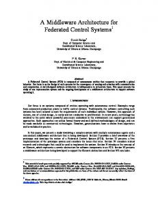
Types of Controllers It would be desirable if all controllers in a control system could be of the same type. This would make the architecture simpler to understand and implement. The requirements on controllers at opposite ends of a control hierarchy, however, are very different. In the upper levels of many systems, it is essential to be able to perform schedule negotiation, plan parsing, resource allocation, and time-consuming remote data access operations. At the lower levels of many systems, it is essential to be able to react to events in a few milliseconds, while plan parsing, resource allocation, scheduling, and remote data access are irrelevant. We feel intuitively that it will be more effective to include different types of controllers in the architecture for the high and low levels of a controller hierarchy. Our analysis of the consequences of having two types of controllers with these different capabilities indicates that it will probably be necessary to have a third type to mediate between them. Thus, the joint architecture has three basic types of controllers: Scheduled Control Units (SCU), Real-Time Control Units (RTCU), and Transition Control Units (TCU). Scheduled Control Units, patterned after the MSI generic controller, are to be used at high levels of control where real-time response is not required, or where there is the need to manage the allocation of resources among controllers which do not have the same immediate superior. Real-Time Control Units are to be used when real-time control is required or when sensory input must be processed. Transition Control Units are to be used as superiors of RTCUs and subordinates of SCUs. The job of TCUs is to bridge between the two operational paradigms discussed in Section 3.2.3.3. A TCU is not required if the RTCU can parse ALPS plans and participate in the Schedule Negotiation Protocol3. Each of these types of controllers is discussed in the following sections. When resource allocation is not a problem and real-time operation is not forestalled by potentially untimely database or communications operations, most or all of the control hierarchy may be composed of RTCUs. And when real-time demands are modest but scheduling is required throughout the control system, an entire hierarchy might be composed of SCUs. Figure 1 shows some sample permitted configurations for controllers in the joint architecture. If further analysis shows that an architecture can perform well in most situations with only one type of controller, we will drop the multiple types.
3. Or in the subset of the ALPS plans and Schedule Negotiation Protocol which the implementation requires.
15
Reference Architecture Interim Report
SCU SCU TCU RTCU
RTCU RTCU
RTCU
RTCU
RTCU RTCU
RTCU
1. This diagram illustrates a hierarchy with an SCU-type controller at the top. The hierarchy has an SCU which supervises both a TCU and an RTCU. On the other side of the hierarchy, there is a hierarchy consisting solely of RTCUs. RTCU RTCU RTCU
RTCU RTCU
RTCU
RTCU
2. This diagram illustrates a hierarchy consisting of entirely RTCUs. This may be appropriate in situations where the control system reacts primarily on sensory data. SCU TCU RTCU
SCU RTCU
SCU
TCU
SCU RTCU
RTCU RTCU
RTCU
RTCU
3. TCUs can occur at any level or not at all, depending on the needs of the application. In cases where an SCU directly supervises an RTCU, the RTCU must perform the functions expected of a TCU.
Figure 1. Sample Permitted Configurations for the Joint Architecture
16
Reference Architecture Interim Report
Scheduled Control Units Scheduled Control Units (SCU) are a specialization of the MSI control entity [Wallace]. We will assume that the SCU contains both a controller (which executes tasks) and a planner (which schedules the controller). Although MSI allows other configurations of planners and controllers, it is not immediately clear whether the joint architecture needs or can use this flexibility. In the configuration chosen for the SCU, conformance to the planner-to-controller portion of MSI’s schedule negotiation message suite is optional. An SCU parses and executes ALPS plans and provides scheduling and rescheduling for ALPS plans when required. An SCU supports the schedule negotiation message suite. An SCU has a subset of the five interfaces required by the MSI architecture. Of the interfaces listed in Section 3.2.4.2.3, all SCUs must have interfaces 1-4. The specification for interface 5 may be used if desired. Processing in the shop is initiated when the Shop level control unit receives an order for parts to be produced. It is expected the Shop level control unit will usually be an SCU. At this point, the method by which an SCU is notified that an order exists and the method by which an appropriate tree of ALPS plans is retrieved or generated, are not specified by the architecture. For SCUs that are not at the shop level, processing is initiated when an appropriate message is received from the superior controller. This message contains a pointer to the plan to be executed and the input parameters for the plan. SCUs use the interrupt-driven control paradigm. The rationale for this is that, since there is so much information which may affect the control unit, it is not practical to poll every bit of information. Instead, the control unit is notified when something changes which may make a difference. Changes which produce events are such things as: a change in the status of a resource affecting the control unit, receipt of a message from the subordinate or superior, and changes in semaphores or locks. The disadvantage of this approach is that the code for the SCU is complex. Real-time Control Units The Real-time Control Unit (RTCU) is a specialization of the RCS controller. As indicated in the Feasibility Report, [Kramer] there are several variations upon the basic RCS architecture [Albus1], [Albus2], [Albus3], [Barbera], [Herman], [Quintero]. While the joint architecture will attempt to permit as many of these variations as possible, choices may be made to obtain a working architecture. As previously stated in Section 3.2.3.2, an RTCU operates on sensory information from the environment, processing it into an internal representation, determining appropriate actions, and performing them (with actuators). Following the RCS architecture, the internal representation of selected features of the environment and the state of the RCS system is termed the world model of the system. The world modeling architectural unit
17
Reference Architecture Interim Report
governs interactions with the world model. In addition to world modeling and the associated world model, an RTCU includes three other architectural units. The four internal architectural units of an RTCU are: (1)
Sensory Processing (SP)—which processes sensory information for insertion into the world model.
(2)
World Modeling (WM)—which controls access to the world model.
(3)
Value Judgment (VJ)—which determines the course of action to take in responding to the environment.
(4)
Behavior Generation (BG)—which generates the actions of the system.
Behavior generation is further decomposed into three parts: (1)
Job Assignment (JA)—which decomposes tasks into subtasks and assigns them to subordinates.
(2)
Planning (PL)—which orders the subtasks into a temporal sequence.
(3)
Execution (EX)—which performs the designated subtasks.
A parallel exists between the SCU’s planner and controller, and an RTCU’s planning and execution. A variety of plan representations are used by RTCU’s ranging from state tables [Barbera], [Quintero] to directed graphs having some of the same features as ALPS. A command and status interface exists between BG in adjacent control levels. This command and status interface is not standardized by the architecture, but in all cases task execution can be initiated by naming a work element and passing appropriate parameters. RTCUs can operate using either a cyclic execution control paradigm or an interrupt-driven control paradigm. Neither paradigm poses a problem for integration, provided that a TCU is an immediate superior. In an RTCU, the amount of information that is to be processed or exported during control unit operation must be limited to what can be handled quickly enough to meet the real-time requirements of the RTCU. It is anticipated that real-time requirements of many applications will preclude having an RTCU handle information not available through the processor on which the RTCU is running or through another processor on the same backplane. To integrate with the shop, it is necessary to export to the supervising TCU the status of the physical equipment which the RTCU is operating and the status of tasks which it is performing. It is also desirable that the RTCU have a notion of a system wide clock so that it can report on task status and timing. Obtaining equipment status and system clock time may be so timeconsuming that an RTCU cannot do it and meet its real-time requirements. If an RTCU cannot provide these, the supervising TCU must supply this information. Recovery from an unforeseen error affecting controllers outside the part of the control hierarchy subordinate to the RTCU experiencing the error cannot be performed for control units at a lower level of control than that RTCU.
18
Reference Architecture Interim Report
RTCUs have the ability to provide the following services to aid in error detection and recovery: (1)
detect when a subordinate has failed,
(2)
abort task execution, and
(3)
halt task execution and discard all information related to the task.
The other functions required for full participation in the error-recovery of the shop listed in Section 3.2.4.2.3 must be provided by the supervising TCU. Transition Control Unit Transition Control Units are responsible for bridging between SCUs and RTCUs. The exact functions which the TCU performs depends upon the capabilities of the RTCU to which it is interfacing. Therefore, it is unclear how generic a TCU can be. While it is desirable that a TCU be generic, it is more important that it is possible to build a TCU with the desired capabilities. With this in mind, we look at the functions required of a TCU and mechanics for building such a TCU. A TCU is required to be able to parse ALPS plans and participate fully in the Schedule Negotiation Protocol. It is unclear if it is desirable for a TCU to control equipment itself directly. As this makes the functional description more complex, we will assume that it cannot. If the RTCU which it supervises is not capable of performing the functions requested, the TCU is responsible for translating the message or ALPS plan node, substituting a related message or node or simulating the required action, instead of passing the function down. Additionally, a TCU must ensure that appropriate information about the RTCU is available to allow the TCU to participate in the execution of the ALPS plan and the Schedule Negotiation Protocol. We will discuss each of these in turn. Participation in ALPS Plan Execution While this discussion does not assume a detailed knowledge of each of the types of nodes in ALPS, it is helpful to know that ALPS nodes fall into several general types. These are: (1)
Task Nodes—which contain a description of work to be done.
(2)
Information Nodes—which contain a description of information to be retrieved for use by the plan.
(3)
Navigational Nodes—which mark the start and end of a plan and allow choices of which plan branches are executed.
(4)
Synchronization Nodes—which provide for synchronizing paths in a single plan or paths in plans for controllers in separate parts of a hierarchy (see Section 3.2.4.2.1).
(5)
Resource Nodes—which describe resources which can be used.
A more detailed discussion of the nodes may be found in [Catron], [Ray], [Barkmeyer].
19
Reference Architecture Interim Report
Each type of node poses its own unique challenges to the TCU. We will start with discussing task nodes. Like the SCU, a TCU needs to have the ability to reference a system-wide clock to see whether it is on schedule and to accommodate ALPS nodes which require a notion of external time. Designing such a clock for a variety of platforms is a great technical challenge. This is eased somewhat because the clock is explicitly not to be used for sequencing messages. Therefore, the degree of accuracy can be set at an acceptable level. Although it is desirable that a RTCU can report its own time, it may be necessary for the TCU to keep track of the time for the subordinate RTCU. When an ALPS node indicates that it should start at a particular time, the TCU will give the command at the correct time4. It will use the available time to update the status of the node and the resources associated with its subordinate and to determine whether a task is on-time, etc. This will limit the ability of the hierarchy to recover from errors to the level of the highest RTCU only, which may not be adequate, but is the best that can be done in this arrangement without a serious violation of the hierarchical control principle that the superior does not know the internals of the subordinate controller. The form of mediation between the ALPS plan which the TCU is given and the plan(s) which the subordinate RTCU expects is dependent on the type of plans which the RTCU expects. In the simplest case, the RTCU can perform only one task, generated by one plan; then the passing of the plan is moot. If the RTCU has the ability to choose the plan which it executes dynamically, the name of the plan can be passed down in an ‘execute’ command with the other plan parameters. If an RTCU uses plans which are state tables, the RTCU will be able to recover only from those errors for which error states and recovery actions have been included in plans. Part of the responsibility of the TCU is to know which parameters are valid for the subordinate and which are not. For example, a subordinate might need to know the feed and speed going with a milling command, but a subordinate might not know how to handle a request for information from a database, and the TCU would need to place an appropriate form of the retrieved data into the form and the location that the RTCU requires. Interactions of a TCU with an RTCU may require the TCU to have detailed knowledge of the internals of the RTCU. They might even require certain hardware accommodations; if the RTCU is on a personal computer and uses shared memory to store its world model, the TCU might need to run on a (different) personal computer (pc) processor which had access to the same pc memory board as well. One presumes that such arrangements need only be made with the lowest levels of control, where the cycle time is fast and the response requirements are great.
4. Note that this means that the RTCU supervised by a TCU will not be able to queue commands at its level, although it may allow its subordinates to queue commands.
20
Reference Architecture Interim Report
A more generic TCU might be achieved by determining which types of information about the RTCU are normally needed (e.g. parameters, world model storage locations, types, names, and parameters of specific plans, execution times of plans with various parameter values, stopping, starting, resuming, and replanning abilities of the RTCU, and a description of the resources controlled by the RTCU and their status, resource consumption). An RTCU could modify its execution of the plan based upon sensory input. In this case, it would be desirable for the RTCU to have some way of exporting its new expected ending date and time to the TCU. Handling nodes for processing information and navigation requires the TCU to access information about both the Shop, itself, and the resources which the subordinate RTCU manages, and to make the appropriate choices. This is a service for the (hard) real-time controller which cannot handle queries and information processing of indeterminate duration. Synchronization nodes pose more of a challenge for the TCU. Since the RTCU is not expected to have the same notions of semaphores and locks as ALPS, the TCU must handle this. This means that, like resources, plans can only be synchronized at the level of the RTCU immediately below the TCU. Whether this will be enough synchronization capability to permit the system to function fully must be investigated by looking at the application of the architecture to a number of specific cases. If this does not prove sufficient, it may be possible to allow an exception to strict hierarchical control, whereby the superior could know more about the plans and resources of some part of the RTCU hierarchy below the immediate subordinate. Finally, since RTCUs only use the concept of exclusive resource allocation, the TCU must simulate all other types of resource allocation by updating the appropriate resource description for the overall shop model. By virtue of the plans, the proper resource allocations will be maintained. Participation in the Schedule Negotiation Protocol As previously indicated, RTCUs already support some of the functionality required for participation in the Schedule Negotiation Protocol. The other functionalities can be supported to various degrees based on the capabilities of the controller. In some cases, the functionality cannot be supported by the RTCU which the TCU supervises. In these cases, the TCU must determine an acceptable alternative command to pass down to the RTCU to support the following functions: (1)
Detect when a subordinate’s task is late. If the RTCU can detect when its subordinate’s task is late, it may pass this information up to the TCU, which can negotiate appropriately. If the RTCU cannot detect when its subordinate’s task is late, the TCU must assume that the task is on time, until the RTCU it supervises is late.
(2)
Estimate task completion time and alter task execution based on new parameters (e.g., new start, completion times). If the RTCU can detect that the task completion time has changed from the standard for that plan, it may pass this information up to the TCU, which can
21
Reference Architecture Interim Report
negotiate appropriately. If the RTCU cannot detect when the task completion time has changed from the standard for that plan, the recovery mechanism will not be able to operate until the RTCU is late. (3)
Halt task execution and retain information to restart later. If the TCU is halted and instructed to save all information necessary to resume the task later, and if the RTCU it supervises can save its information, the RTCU simply waits for the TCU to resume execution. If the RTCU is not capable of performing this, the TCU can either save all the information for the subordinate controller and its place in the plan, or it can issue a response to the superior controller that this task has not been successful. The latter option will produce a halt or an abort.
(4)
Restart task execution from the previous point, This depends upon the TCU having a notion of which of the RTCU’s tasks can be resumed safely, which can be repeated safely and which cannot. If a task can be repeated, the TCU can simulate the correct behavior by reissuing the original task. If the RTCU has the notion of restarting a task, the TCU can then tell the RTCU to restart. Otherwise, a negative response for the request will be sent, resulting in the task being halted or aborted.
(5)
Halt task execution and regard the task as complete. Given that most RTCUs do not keep a record of previously performed tasks, this requirement is merely a requirement for the TCU to update the ALPS plan with the ‘complete’ state.
A re-thinking of the Schedule Negotiation Protocol might produce a more satisfactory solution to 3 and 4. 3.2.4.2.5
Controller Interfaces When the control system is in operation, controllers of all types need interfaces for a human or other intelligent agent to provide monitoring and intervention. Exact requirements for the joint architecture have yet to be determined, but the current practices in the MSI and RCS architectures can be used as input. MSI controllers (on which SCUs are based), have an interface called the guardian which provides external support for external monitoring and intervention. It is designed to be used primarily for user intervention when automatic error recovery cannot be done. A guardian interface may be either passive, which is used for monitoring only, or active, which can also provide intervention. A controller can have any number of passive guardian interfaces, but only one active guardian interface. A guardian interface has specific messages which may be sent to and from the controller. Details are given in the Schedule Negotiation Protocol (see Section 3.2.4.2.3). The intelligent user is permitted to alter quite a few aspects of task execution, but may alter only limited aspects of task planning.
22
Reference Architecture Interim Report
RCS controllers (on which RTCUs are based), have a user interface for each controller the details of which are left to the implementor. Frequently, the monitoring interface can be used to track data exchange between controllers and alter virtually any aspect of task planning or execution. 3.2.4.3
Communications For the levels of the architecture which participate in the Schedule Negotiation Protocol, communication channels for command and status messages must use a point to point, guaranteed message communication paradigm. Such a protocol is provided by the Manufacturing Automation Protocol (MAP) [MAP1], [MAP2], with the Manufacturing Messaging Specification (MMS) application layer [ISO2]. However, the use of Ethernet/TCP/IP instead of the Token Bus (as required by MAP) [Tanenbaum] has been more workable in our experience in the past and is strongly encouraged in future implementations of the joint architecture. The requirement of point to point communication for command and status may be softened to allow other forms of communication (such as communication via a memory board in a backplane shared by the processors on which the command and status senders are running) provided that the communication method is used to send command and status messages from one specified party to another specified party. For control units in the architecture which use ALPS plans, some type of communications mechanism which permits data to be read by multiple readers who are not known in advance must be used to implement locks and other synchronization structures. NIST’s Common Memory [Libes], [Rybczynski] provides such a mechanism, as do databases. For other required communications, standard communication protocols such as Ethernet/TCP/IP or RS-232 [EIA] can be used. For processes running in the same computer, shared memory may be available, as may a common bus.
23
Reference Architecture Interim Report
3.3
Framework for the Joint Architecture and Description via the Framework This section gives an overview of the framework of the joint architecture and a tier-bytier description of the architecture. An incomplete model of the joint architecture written in the EXPRESS language is included in this report as Appendix B. The EXPRESS model also takes a tier-by-tier view. Sections 3.3.4 through 3.3.6 of the text are natural language equivalents of the major sections of the EXPRESS model. Reading and understanding these sections requires no knowledge of EXPRESS. Large portions of the text in this section are identical to comments in the EXPRESS model. If there is any deviation of the English language description of the EXPRESS model from the EXPRESS model description here, it is unintentional, and the EXPRESS model should be regarded as definitive.
3.3.1
Textual Description Methods Starting with Section 3.3.4, the text in this section consistently uses the same constructions for the same purposes. The motivation for this is to provide as unambiguous a description as possible of what is intended. The textual description of the architecture presented here uses the same approach as many object-oriented languages, including EXPRESS. The model is comprised largely a number of class definitions. Each class has a name, may be derived from another class, may have other classes derived from it, and may have a number of attributes. The data type of each attribute is either a universally recognized type (such as an integer) or is one of the other classes defined in the model. If class B is derived from class A, class B will have all the attributes that A has, and it may have additional attributes A does not have. Also, if class B is derived from class A, the data type of an attribute of B may be constrained from the data type of the same attribute of A. For example, if the data type of the “favorite_food” attribute of A is “meat”, the data type of the “favorite_food” attribute of B might be constrained to be “beef”. Thirdly, if class B is derived from class A, we will say that “B is a kind of A”, or “an A may be a B”. We will not use “kind of” or “may be a” in any other sense in this section. If class B is derived from class A and class C is derived from class B, it is implicit that C is a kind of A. We could say that explicitly, but we will not do so in this section, to avoid adding confusion. Where class A has attribute B, which must be of type C, we say, “C serves as the B of A”. Except at the first level of subsections of this section (which have numbers like 3.3.1 or 3.3.2), the remaining subsections of this section are organized hierarchically. Where B is a kind of A, a description of B will either be given as a subsection of the description of A or as part of the same subsection that describes A. Two varieties of classes of are needed to define the joint architecture: those that describe generic components and those that describe which specific sorts of the generic components are put together to form the architecture. An analogy is that in specifying
24
Reference Architecture Interim Report
the designs of pieces of furniture (whose generic components include wood), it is necessary to have terminology for identifying different types of wood (such as “pine”, “oak”, and “cherry”) in order to say which specific type of wood is to be used for a given piece of furniture. In several cases in the joint architecture, a generic component is defined as the singular form of a term (such as “architectural_specification”) while use of the component is identified by the plural form of the same term (such as “architectural_specifications”). We have not tried to segregate the two varieties of classes in the organization of this section. Terms defined in the EXPRESS model by using underscores to convert a phrase into a single word are written using underscores in this section, rather than with spaces. Thus, for example, “control architecture” becomes “control_architecture”. Other typographic devices for clarifying meaning, such as using different fonts, are not used here to avoid taxing the reader’s eyes, but are used in Appendix B. 3.3.2
Framework Overview As noted earlier, the joint architecture conforms to the conceptual framework presented in Section 2.1. That is, it has explicit tiers_of_architectural_definition, and the elements_ of_architectural_definition are defined at each tier. The joint architecture has five tiers. The lowest two or three tiers are intended to be defined differently for different applications and implementations, with little or nothing from those tiers specified beforehand, provided, of course, that they conform to all the higher tiers of the architecture. This section describes only the top two tiers of the joint architecture. Appendix B includes all five tiers, but the lowest three tiers are empty shells. In addition to the five tiers of the joint architecture, many generic control architecture concepts are needed as the foundation for building the tiers. These concepts are described in Section 3.3.4 and may be thought of as comprising tier 0 of the joint architecture. They are very general, however, and could equally well serve as the foundation for radically different architectures.
3.3.3
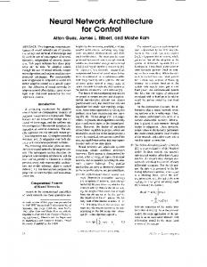
Model Overview Following the framework, the model of the architecture is composed of an EXPRESS schema for the framework itself (the generic control architecture) and five separate EXPRESS schemas, one for each tier of architectural definition. The overall form of the model is shown in Figure 2.
25
Reference Architecture Interim Report
schema: Generic Control Architecture control architecture
tier of archit. definition
element of archit. definition
architectural unit
schema: Tier 1 Hierarchical Control scope
purpose
analyses
architectural methodology conformance specifications for arch. dev. criteria
schema: Tier 2 Discrete Parts scope
purpose
analyses
architectural methodology conformance specifications for arch. dev. criteria
schema: Tier 3 scope
purpose
analyses
architectural methodology conformance specifications for arch. dev. criteria
schema: Tier 4 scope
purpose
analyses
architectural methodology conformance specifications for arch. dev. criteria
schema: Tier 5 scope
purpose
analyses
architectural methodology conformance specifications for arch. dev. criteria
Figure 2. EXPRESS Model of Joint Architecture - Overall Form The generic control architecture model has several important classes: control_ architecture, tier_of_architectural_definition, element_of_architectural_definition, and architectural_unit. These classes correspond directly to the concepts in Section 2.1.2 and Section 2.1.3. The correspondence between the EXPRESS model and the operational description of the architecture in Section 3.2 is less immediate. The following sections discuss highlights of the correspondence to give the reader an overall feel for how the two descriptions relate.
26
Reference Architecture Interim Report
The description of the architecture in Section 3.2.4 gives architectural_specifications. These architectural_specifications consist of information_specifications, communications_specifications, and functional_specifications, corresponding to key aspects of the architectural_specifications listed in the previously referenced section. We will discuss each of these specifications. 3.3.3.1
Information_Specifications The information_specifications of the joint architecture discuss the storage mechanism for data, the information access paradigm for the data and the semantics of the data itself. The physical storage location for a datum is of class data_store, which may be a temporary or a permanent place for data storage. A data_store has an associated data_store_manager which accesses the data_store. A party which communicates with one or more other parties is an interactive_unit. Interactive units communicate via an interaction specification. In the model, a nonspecific interaction specification is represented by the class generic_interaction_specification. There are two fundamentally different types of generic_interaction_specifications, direct_interaction_specification and indirect_interaction_specification. In an indirect_interaction_specification, a set of permitted_stored_data_units (which consist of data_units) may be stored in one or more data_stores through the associated data_store_managers. The indirect_interaction_specification specifies any number of interactive_units which may read the data in the data_store and any number of interactive_units which may write the data in the data_store. Conflict among the interactive_units permitted either read_access, write_access or both is resolved according to the access_scheme which is associated with the indirect_interaction_specification. In a direct_interaction_specification, the physical moving of bits from one interactive_unit to another is accomplished via a communication_method. Data_units are exchanged via messages with a message_content. The mode of interaction is given by an interaction_protocol which specifies the two interacting parties (labelling them first_party and second_party) and giving a set of message_protocols which may be used for the communication. Note that since the model allows only two interacting parties, direct communication is explicitly point-to-point. In the case where one of the interacting parties is a data_store_manager, the data_store manager controls the access to the data_store by the parties specified in an data_interaction_setup, according to the rules set forth by a data_interaction_protocol. In the interaction, data_messages are exchanged. Data messages can be either to or from the data_store. Data_messages are part of a data_message_protocol. There is no analog to this protocol description of architecture given in Section 3.2.4.3, where communication via database or Common Memory is indirect.
27
Reference Architecture Interim Report
In the case where neither of the parties is a data_store_manager, the two interactive_units specified in a functional_interactive_setup communicate by exchanging functional_messages according to the rules set forth by a functional_interaction_protocol. Functional_messages may be either command or status messages and are part of a functional_message_protocol. The functional_message_protocol specified in the joint architecture is the Schedule Negotiation Protocol (SNP). The full details of the messages specified in the SNP is not yet part of the model of the joint architecture, although it may appear at a lower tier_of_ architectural_definition. The data represented in the joint architecture in the information models is not yet fully represented in the EXPRESS model. Certain elements are stubbed out: for example, plans (and derived types process, production, and schedule plans), resources, and message information. 3.3.3.2
Communication_Specifications As previously discussed, the EXPRESS model represents both indirect communication via a database or other data storage location and direct communication via message exchange. Both paradigms are supported by the architecture. The presently filled in tiers of the architecture do not include a communications specification detailed enough to discuss MS, RS-232 or other standards described in Section 3.2.4.3.
3.3.3.3
Functional_Specifications The functional_specifications of the architecture are described by the subclasses and relationships of system_activity. The primary activities of the system are planning and control. Planning has the expected derived types process_planning, production_management_planning, and schedule_planning. Parts of the EXPRESS model having to do with planning and control are shown in Figure 3. It will be necessary to add subtypes to “plan” for those plans which are used by RTCUs. Our initial hope of using the “process_plan” subtype or the parent “plan” for RTCUs does not seem workable.
28
Reference Architecture Interim Report
architectural_unit
interactive_unit
functional_unit
data_unit
data_store_manager managed_store: data_store
data_store
control_unit
planner output: plan
plan
scheduled_control_unit
process_ planner SELF\planner.output: process_plan
process_plan
transition_control_unit
real_time_control_unit
production_management_ planner SELF\planner.output: production_managed_plan
schedule_ planner SELF\planner.output: schedule
production_managed_plan antecedent_process_plan: process_plan
schedule antecedent_managed_plan: production_managed_plan
KEY Each box defines an entity, including name and attributes, with data type of each attribute bold = entity name italic: roman = attribute name followed by data type of attribute = pointer from attribute type to type definition = connection from supertype above to subtype below = connection to subtypes not shown
Figure 3. Planning and Control in EXPRESS Model of Joint Architecture
29
Reference Architecture Interim Report
The planning and control functions are performed by a special type of interactive_unit called a functional_unit. Functional_units are specialized as control_units and planners. There are three types of planners: process_planners, production_management_planners, and schedule_planners which perform process_planning, production_management_planning, and schedule_planning, respectively. Planners produce plans: Process_planners produce process_plans; production_management_planners produce production_managed_plans, and schedule_planners produce schedules. Control units operate using plans of one of these three sorts, although this fact is not reflected anywhere in the EXPRESS model. Control_units perform control functions. A control_unit is part of a superior_and_subordinate (complex). A control_unit has at most one superior in the superior_and_subordinates and may have zero or more subordinates. A control_unit may be either a scheduled_control_unit, real_time_control_unit, or a transition_control_unit. The characteristics of these different types of control_units are discussed in Section 3.2.4.2.4. The handling of functional units should be re-examined because the current model does not provide for building functional units from other functional units, and it is expected that some mechanism for combining subunits will be required. 3.3.4
Generic_Control_Architecture The “generic_control_architecture” is the most abstract level of the model of the joint architecture. This section gives the many detailed definitions which are required to specify unambiguously what is intended. It should be noted that other models exist for some of these concepts — communications and data, in particular. The intent of the model described here is to specify those aspects of these concepts which are relevant to control systems. Further study of existing models should be undertaken to determine if they are usable in the context of control systems.
3.3.4.1
Control_Architecture A control_architecture is not a kind of anything else and has attributes: tiers_of_architectural_definition (which is an ordered list of tiers) and an overall_methodology (which is a methodology_for_architectural_development). The tiers are ordered by degree of abstraction, as described earlier. A control_architecture may be a hierarchical_control_architecture (see Section 3.3.5). Other types of architectures could be defined which are kinds of control_architecture. A control_architecture does not serve as part of any other defined thing. The overall_methodology is a methodology_for_architectural_development which is applicable to the entire architecture, not just to a single tier. For example a general approach, such as “define tiers from the bottom up” lies outside any one tier and applies to the architecture as a whole.
30
Reference Architecture Interim Report
3.3.4.2
Tier_of_Architectural_Definition A tier_of_architectural_definition is not a kind of anything else and has attributes: tier_scope (a scope), tier_purpose (a purpose), tier_analyses (an analyses), tier_architectural_specifications (an architectural_specifications), tier_methodology (a methodology_for_architectural_development), and tier_conformance_criteria (a conformance_criteria). The tier_methodology is a method of building lower or higher tiers. Tier_of_architectural_definition serves as one element in the list of tiers (of architectural definition) of a control_architecture. The concept tier_of_architectural_definition is the same one as that discussed in Section 2.1.3.
3.3.4.3
Element_of_Architectural_Definition An element_of_architectural_definition is not a kind of anything else and may be a: scope, purpose, analyses, architectural_specifications, methodology_for_ architectural_development, or conformance_criteria. Note that scope and purpose are two separate items here. An element_of_architectural_definition does not serve directly as part of any other defined thing. The elements_of_architectural_definition are the same as those discussed in Section 2.1.2. The EXPRESS definitions of elements_of_architectural_definition and the relationships among them are shown in Figure 4.
31
Reference Architecture Interim Report
element_of_architectural_definition
purpose
scope
j_purpose_one restriction1: purpose_restriction
j_scope_one restriction1: scope_restriction
j_purpose_two restriction2: purpose_restriction
j_scope_two restriction2: scope_restriction
j_purpose_three restriction3: purpose_restriction
j_scope_three restriction3: scope_restriction
j_purpose_four restriction4: purpose_restriction
j_scope_four restriction4: scope_restriction
j_purpose_five restriction5: purpose_restriction
j_scope_five restriction5: scope_restriction
methodology_for_architectural_development
conformance_criteria criteria: set of zero or more conformance_criterion
analyses information_analyses: set of zero or more information_analysis functional_analyses: set of zero or more functional_analysis dynamic_analyses: set of zero or more dynamic_analysis other_analyses: set of zero or more other_analysis architectural_specifications communications_specifications: list of zero or more communication_specification functional_specifications: list of zero or more functional_specification hardware_specifications: list of zero or more hardware_specification information_specifications: list of zero or more information_specification language_specifications: list of zero or more language_specification other_specifications: list of zero or more other_specification
Figure 4. Elements of Architectural Definition in EXPRESS Model of Joint Architecture (see key on Figure 3)
32
Reference Architecture Interim Report
3.3.4.3.1
Scope A scope is a kind of element_of_architectural_definition. A scope is the range of areas to which an architecture is intended to be applied. It is expected that the scope of each lower tier of a control_architecture will be defined as a kind of the scope of the preceding tier, with an added attribute; the attribute will be a scope_restriction, which may be unstructured text. The scope_restriction serves to further limit the scope which was described in the preceding tier. A scope may be a j_scope_one; see Section 3.3.5. A scope serves as the tier_scope of a tier_of_architectural_definition. The initial scope for the joint architecture is given in Section 3.2.1, Section 3.3.5.1, and Section 3.3.6.1.
3.3.4.3.2
Purpose A purpose is a kind of element_of_architectural_definition. A purpose is a statement of what the architecture is intended to help accomplish within the scope of that tier. It is expected that the purpose of each lower tier of a control_architecture will be a defined as a kind of the purpose of the preceding tier, with an added attribute; the attribute will be a purpose_restriction, which may be unstructured text. The purpose_restriction serves to further limit the purpose which was described in the preceding tier. A purpose may be a j_purpose_one; see Section 3.3.5. A purpose serves as the tier_purpose of a tier_of_architectural_definition. The initial purpose for the joint architecture is given in Section 3.2.1 and Section 3.3.5.2.
3.3.4.3.3
Analyses An analyses is a kind of element_of_architectural_definition. An analyses is a collection of analyses that should be performed. An analyses has attributes: information_analyses (which is a set of information_analysis), functional_analyses (which is a set of functional_analysis), dynamic_analyses (which is a set of dynamic analysis), and other_analyses (which is a set of other_analysis). An analyses serves as the tier_analyses of a tier_of_architectural_definition. The initial domain analyses for the joint architecture are given in Section 3.2.3.
3.3.4.3.4
Architectural_Specifications An architectural_specifications is a kind of element_of_architectural_definition. An architectural_specifications has attributes: communications_specifications (which is a list of zero to many communications_specification), functional_specifications (which is a list of zero to many functional_specification), hardware_specifications (which is a list of zero to many hardware_specification), information_specifications (which is a list of zero to many information_specification), language_specifications (which is a list of zero to many language_specification), and other_specifications (which is a list of zero to many other_specification). Of course, at least some of these elements must be nonzero in order for the architecture to have any content. 33
Reference Architecture Interim Report
An architectural_specifications serves as the tier_architectural_specifications of a tier_of_architectural_definition. 3.3.4.3.5
Methodology_for_Architectural_Development A methodology_for_architectural_development is a kind of element_of_architectural_ definition. A methodology_for_architectural_development is a set of procedures for applying an architecture. A methodology_for_architectural_development serves as the overall_methodology of a control_architecture and as the tier_methodology for a tier_of_architectural_ development.
3.3.4.3.6
Conformance_Criteria A conformance_criteria is a kind of element_of_architectural_definition. Conformance_criteria are criteria which specify how an architectural_unit at one tier of an architecture conforms to the architectural_specifications of a higher tier, or how a process for building part of an architecture conforms to the development methodology given by the architecture for building that part. A conformance_criteria has one attribute: criteria (which is a set of conformance_criterion). A conformance_criteria serves tier_of_architectural_definition.
3.3.4.4
as
the
tier_conformance_criteria
of
a
Architectural_Unit An architectural_unit is an atomic or molecular unit that is recognized by an architecture. An architectural unit is not a kind of anything else and may be an access_scheme, an analysis, an architectural_specification, a communication_method, a conformance_criterion, a control_hierarchy, a data_unit, a generic_interaction_ specification, an interaction_setup, an interactive_unit, a message_protocol, a planning_model, a resource, a superior_and_subordinates, or a system_activity. All these except control_hierarchy, resource, and superior_and_subordinates are discussed immediately below. The notions of superior_and_subordinates and control_hierarchy are introduced in tier1 of the joint architecture (not in generic control architecture) and are described in Section 3.3.5. Resource is defined in tier 2 and is described in Section 3.3.6. An architectural_unit does not serve directly as part of any other defined thing. The model given here needs improvement. Several things which are kinds of architectural_unit (such as generic_interaction_specification, control_hierarchy, and communication_method) should be kinds of one of the kinds of architectural_ specification, instead. For example, a control_hierarchy should be a kind of functional_specification.
34
Reference Architecture Interim Report
3.3.4.4.1
Access_Scheme An access_scheme is a kind of architectural_unit. An access_scheme describes the reading and writing access of interactive_units to the various stored_data_units involved in an indirect_interaction_specification. It also describes any locking mechanism that may be used. An access_scheme serves as the scheme of an indirect_interaction_specification.
3.3.4.4.2
Analysis An analysis is a kind of architectural_unit. An analysis is the examination of the components of some complex system and how they relate to one another. An analysis may be a dynamic_analysis, a functional_analysis, an information_analysis, or an other_analysis. An analysis does not serve directly as part of any other defined thing.
3.3.4.4.2.1 Dynamic_Analysis A dynamic_analysis is a kind of analysis. A dynamic analysis is an analysis of the characteristics of the function and information in a domain which vary over time during control system operation. It provides qualitative and quantitative information about the sequence, duration, and frequency of change in the function and information of the domain. A dynamic_analysis serves as one of the dynamic_analyses of an analyses. 3.3.4.4.2.2 Functional_Analysis A functional_analysis is a kind of analysis. A functional_analysis is an analysis of all the activities within the scope of an architecture which a conforming system is supposed to be able to perform. A functional_analysis serves as one of the functional_analyses of an analyses. 3.3.4.4.2.3 Information_Analysis An information_analysis is a kind of analysis. An information_analysis is an analysis of all the information within the scope of an architecture needed for a conforming system to function properly. An information_analysis serves as one of the information_analyses of an analyses. 3.3.4.4.2.4 Other_Analysis An other_analysis is a kind of analysis. An other_analysis is a kind of analysis which is not an information_analysis, functional_analysis, or dynamic_analysis. An other_analysis serves as one of the other_analyses of an analyses.
35
Reference Architecture Interim Report
3.3.4.4.3
Architectural_Specification An architectural_specification is a kind of architectural_unit. An architectural_specification is a prescription of what the pieces (software, languages, execution models, controller models, communications models, computer_hardware, machinery, etc.) of an architecture are, how they are connected (logically and physically), and how they interact. An architectural_specification may be a communications_specification, a functional_ specification, a hardware_specification, an information_specification, a language_ specification, or an other_specification. An architectural_specification does not serve directly as part of any other defined thing.
3.3.4.4.3.1 Communications_Specification A communications_specification is a kind of architectural_specification. A communications_specification describes some aspect of the communications of a control system. A communications_specification serves as one of the communications_specifications of an architectural_specifications. 3.3.4.4.3.2 Functional_Specification A functional_specification is a kind of architectural_specification. A functional_ specification describes part of the functioning of a control system. A functional_specification serves as one of the functional_specifications of an architectural_specifications. 3.3.4.4.3.3 Hardware_Specification A hardware_specification is a kind of architectural_specification. A hardware_ specification describes part of the hardware of a control system. A hardware_specification serves as one of the hardware_specifications of an architectural_specifications. 3.3.4.4.3.4 Information_Specification An information_specification is a kind of architectural_specification. An information_ specification describes part of the information or method of handling information of a control system. An information_specification serves as one of the information_specifications of an architectural_specifications. 3.3.4.4.3.5 Language_Specification A language_specification is a kind of architectural_specification. A language_ specification specifies the use of some particular language for modeling or programming.
36
Reference Architecture Interim Report
A language_specification serves as one of the language_specifications of an architectural_specifications. 3.3.4.4.3.6 Other_Specification An other_specification is a kind of architectural_specification. An other_specification describes part of a control system which cannot be classified as having to do with communications, function, hardware, information, or language. An other_specification serves as one of the other_specifications of an architectural_specifications. 3.3.4.4.4
Communication_Method A communication_method is a kind of architectural_unit. A communication_method specifies a method of getting messages from one interactive_unit to another. It is important to note that two interactive_units are regarded as communicating whenever one sends the other a message. The two interactive_units may be as close together as blocks of code in a single program, or they may be as far separated as running on two different computers which are physically far separated. A communication_method serves as the link_method of an interaction_setup. This part of the model is incomplete. In particular, specific subtypes of communication_method will be defined in the completed joint architecture. Defining these subtypes is expected to be a technical challenge. Many models of communication and many types of communication hardware and software already exist. These will have to be examined. It may be possible to use existing models. We plan to define only communication_methods which can be implemented with existing hardware.
3.3.4.4.5
Conformance_Criterion A conformance_criterion is a kind of architectural_unit. A conformance_criterion specifies how an architectural_unit at one tier of an architecture conforms to the architectural_specifications of a higher tier, or how a process for building part of an architecture conforms to the development methodology given by the architecture for building that part. A conformance_criterion serves as one of the criteria of a conformance_criteria.
3.3.4.4.6
Data_Unit A data_unit is a kind of architectural_unit. A data_unit is any kind of data and may be a data_store, message, message_information, plan, or stored_data_unit. A data_unit does not serve directly as part of any other defined thing.
37
Reference Architecture Interim Report
3.3.4.4.6.1 Data_Store A data_store is a kind of data_unit. A data_store is a physical location where data resides. It may be short-lived (dying with a computer process within which it resides, for example) or long-lived (a file system, for example). A data_store serves as the managed_store of a data_store_manager. 3.3.4.4.6.2 Message A message is a kind of data_unit. A message may be a data_message or a functional_message. A message has attributes: sender (which is an interactive_unit), receiver (which is another interactive_unit), and contents (which is a message_information). A message is used to carry information from the sender to the receiver. A message serves as one of the messages of a message_protocol. Data_Message A data_message is a kind of message. A data_message may message_from_data_store_manager or a message_to_data_store_manager.
be
a
A data_message serves as one of the messages of a data_message_protocol. Message_from_Data_Store_Manager A message_from_data_store_manager is a kind of data_message in which the sender is a data_store_manager. Message_to_Data_Store_Manager A message_to_data_store_manager is a kind of data_message in which the receiver is a data_store_manager. Functional_Message A functional_message is a kind of message in which the sender is a functional_unit and the receiver is a functional_unit. A functional_message may be a command or a status; see Section 3.3.5. A functional_message serves as one of the messages of a functional_message_protocol. 3.3.4.4.6.3 Message_Information A message_information is a kind of data_unit. A message_information is the information content of a message. It is expected that subclasses of message_information defined at lower tiers will specify the structure of the information. A message_information serves as the contents of a message.
38
Reference Architecture Interim Report
3.3.4.4.6.4 Plan A plan is a kind of data_unit. A plan is a scheme developed to accomplish a specific goal. A plan may be a process_plan, production_managed_plan, or schedule. A plan serves as the output of a planner. 3.3.4.4.6.5 Stored_Data_Unit A stored_data_unit is a kind of data_unit. A stored_data_unit describes a stored unit of data. A stored_data_unit has one attribute: manager (which is a data_store_manager which manages the data_store in which the stored_data_unit resides). A stored_data_unit serves as indirect_interaction_specification.
one
of
the
permitted_data_units
of
an
A stored_data_unit may be used in many indirect_interaction_specifications, each of which has (probably different) sets of readers and writers, both of which are composed of interactive_units, which can access the data. Because the relationship between a stored_data_unit and its readers and writers may be complex, the readers and writers are not modeled as part of the stored_data_unit, but rather as part of the indirect_interaction_specifications in which the stored_data_unit is involved. 3.3.4.4.7
Generic_Interaction_Specification A generic_interaction_specification is a kind of architectural_unit. A generic_interaction_specification describes an interaction between two or more interactive_units. A generic_interaction_specification may be a direct_interaction_protocol (in which two interactive_units interact by sending messages to one another) or an indirect_interaction_specification (in which two or more interactive_units interact by access to common data). A generic_interaction_specification does not serve directly as part of any other defined thing.
3.3.4.4.7.1 Direct_Interaction_Protocol A direct_interaction_protocol is a kind of generic_interaction_specification. A direct_interaction_protocol describes the continuing interaction between two interactive_units. A direct_interaction_protocol may be a data_interaction_protocol or a functional_interaction_protocol. A data_interaction_protocol has attributes: first_party (which is an interactive_unit), second_party (also an interactive_unit), and message_protocols (a set, each of which is a message_protocol). Each message_protocol describes a sequence of messages to be passed between the two parties needed to accomplish some specific purpose. A direct_interaction_protocol serves as the interaction_specification of an interaction_setup.
39
Reference Architecture Interim Report
Data_Interaction_Protocol A data_interaction_protocol is a kind of direct_interaction_protocol in which all of the message_protocols are data_interaction_protocols. A data_interaction_protocol data_interaction_setup.
serves
as
the
interaction_specification
of
a
Functional_Interaction_Protocol A functional_interaction_protocol is a kind of direct_interaction_protocol in which all of the message_protocols are functional_message_protocols. A functional_interaction_protocol serves as the interaction_specification of a functional_interaction_setup. 3.3.4.4.7.2 Indirect_Interaction_Specification An indirect_interaction_specification is a kind of generic_interaction_specification. An indirect_interaction_specification describes a continuing interaction between two sets of interactive_units via a set of stored_data_units managed by one or more data_store_managers and mediated by an access_scheme. An interaction_protocol has attributes: readers (which is a set of interactive_units), writers (also a set of interactive_units — possibly only one), permitted_data_units (which is the set of stored_data_units which may be accessed by the readers and writers), a scheme (which is an access_scheme), and managers (which is a set of data_store_managers). The permitted_data_units must all be in the data_stores managed by the managers. An indirect_interaction_specification does not currently serve directly as part of any other defined thing. Note that an indirect_interaction_specification does not specify messages. Messages might well flow between the data_store_managers managing the stored_data_units and the various interactive_units which have access to the permitted_data_units, but that is not relevant here. It might be useful to add a purpose to the definition of indirect_interaction_ specification. 3.3.4.4.8
Interaction_Setup An interaction_setup is a kind of architectural_unit. An interaction_setup is an arrangement between two interactive_units in which they have an agreed method of communicating and an agreed direct_interaction_protocol. An interaction_setup has attributes: first_party (which is an interactive_unit), second_party (which is also an interactive_unit), link_method (which is a communication_method), and interaction_specification (which is a direct_interaction_protocol). An interaction_setup may be a data_interaction_setup or a functional_interaction_setup. A data_interaction_setup does not serve directly as part of any other defined thing.
40
Reference Architecture Interim Report
3.3.4.4.8.1 Data_Interaction_Setup A data_interaction_setup is a kind of interaction_setup in which the second_party is a data_store_manager and the interaction_specification is a data_interaction_protocol. A data_interaction_setup does not currently serve directly as part of any other defined thing, but is expected to be used in lower tiers of the joint architecture. 3.3.4.4.8.2 Functional_Interaction_Setup A functional_interaction_setup is a kind of interaction_setup in which the first_party and the second_party are both functional_units and the interaction_specification is a functional_interaction_protocol. A functional_interaction_setup does not currently serve directly as part of any other defined thing, but is expected to be used in lower tiers of the joint architecture. 3.3.4.4.9
Interactive_Unit An interactive_unit is a kind of architectural_unit. An interactive_unit interacts with other interactive_units of the architecture by sending and receiving messages. Typically, the messages will be commands, status information, data, or requests for data. An interactive_unit may be a data_store_manager or a functional_unit. An interactive_unit serves as the first_party and the second_party of a direct_interaction_protocol, as one of the readers and one of the writers of an indirect_interaction_specification, as the sender and receiver of a message, and as the first_party and the second_party of a message_protocol. The interactive_unit is the basic active element of a control system. All active elements in a control system are subtypes of interactive_unit. The current model is too simplistic regarding interactive_units. In particular, the model defines interactive_unit as an atomic thing with no substructure. However, we may wish to have molecular interactive units. Both RCS and MSI define things which are logically molecular interactive_units: an RCS controller includes world modeling, behavior generation, sensory processing, and value judgement; an MSI control entity includes a planner and a controller. Completing the joint architecture will include redefining interactive_unit and devising a method of combining interactive_units to form larger interactive_units.
3.3.4.4.9.1 Data_Store_Manager A data_store_manager is a kind of interactive_unit and has one attribute: managed_store (which is a data_store). A data_store_manager receives messages about data (primarily requests to store or retrieve data) and acts on them. A data_store_manager also sends messages about data.
41
Reference Architecture Interim Report
A data_store_manager serves as the second_party in a data_interaction_setup, as the sender of a message_from_data_store_manager, as the receiver of a message_to_data_store_manager, as one of the managers in an indirect_interaction_specification, and as the manager of a stored_data_unit. 3.3.4.4.9.2 Functional_Unit A functional_unit is a kind of interactive_unit. A functional_unit may be a control_unit or a planner. As noted earlier, the definition of functional_unit will probably need to be revised to allow functional_units to be composed of other functional_units. A functional_unit serves as the first_party and the second_party of a functional_interaction_setup, as the first_party and second_party of a functional_message_protocol, and as the sender and receiver of a functional_message. Control_Unit A control_unit is a kind of functional_unit. A control_unit performs task execution - as opposed to planning, information handling, sensory processing, etc. A control_unit may be a real_time_control_unit, a scheduled_control_unit, or a transition_control_unit. These correspond to the types of controllers identified in the description of the joint architecture in Section 3.2.4.2.4. A control_unit serves as the sender and receiver of a command (see Section 3.3.5), as the sender and receiver of a status (see Section 3.3.5), and as superior and one of the subordinates in a superior_and_subordinates (see Section 3.3.5). As noted above, it will be desirable that some subtypes of interactive_units be composed of interactive_units. Control_unit is a prime candidate for having substructure. The definition of control_unit will be reconsidered as the joint architecture is defined further. Planner A planner is a kind of functional_unit. A planner is an agent which generates or selects plans to accomplish one or more goals. The one attribute of a planner is output (which is a plan). A planner may be a process_planner, production_management_planner, or schedule_planner. These are defined in tier1 of the joint architecture; see Section 3.3.5. The types of planners and plans correspond to those defined in Section 3.2.3.2. We believe additional types of planners will be needed as we refine the way planning is handled in different subtypes of control_unit. A planner does not serve directly as part of any other defined thing. 3.3.4.4.10 Message_Protocol A message_protocol is a kind of architectural_unit. A message_protocol is a specification of one or more messages which are exchanged between two interactive_units in order to accomplish some specific purpose. A message_protocol may be a data_message_protocol or a functional_message_protocol. Each of these
42
Reference Architecture Interim Report
includes messages of only one type (either data_messages or functional_messages). Further consideration should be given to whether another kind of message_protocol should be defined in which a mixture of message types is allowed. A message_protocol has attributes: first_party (which is an interactive_unit), second_party (which is also an interactive_unit), purpose (which is a message_protocol_purpose), and messages (which is an ordered list of messages). A message_protocol_purpose is a textual statement of the purposed served by a message_protocol. A message_protocol serves direct_interaction_protocol.
as
one
of
the
message_protocols
of
a
As currently defined, a message_protocol can only exist between two interactive_units. It may be desirable to have something like a message_protocol which involves more than two interactive_units. We will consider this as we develop the joint architecture. 3.3.4.4.10.1Data_Message_Protocol A data_message_protocol is a kind of message_protocol in which all the messages are data_messages. A data_message_protocol serves as one of the message_protocols of a data_interaction_protocol. 3.3.4.4.10.2Functional_Message_Protocol A functional_message_protocol is a kind of message_protocol in which the first_party is a functional_unit, the second_party is also a functional_unit, and the messages are all functional_messages. A functional_message_protocol serves as one of the message_protocols of a functional_interaction_protocol. The Schedule Negotiation Protocol described in Section 3.2.4.2.3 is a functional_message_protocol. 3.3.4.4.11 Planning_Model A planning_model is a kind of architectural_unit. A planning model is a model of how planning is done in a control_architecture — the stages of planning, the types of plans, etc. A planning_model may be a j_planning_model (see Section 3.3.5). A planning_model does not serve directly as part of any other defined thing. 3.3.4.4.12 System_Activity A system_activity is a kind of architectural_unit. A system_activity may be control or planning. The system_activity class could be expanded into a full activity model. This has not yet been done.
43
Reference Architecture Interim Report
A system_activity does not serve directly as part of any other defined thing. 3.3.4.4.12.1Control Control is a kind of system_activity. Control is the activity performed by controllers. Control does not serve directly as part of any other defined thing. 3.3.4.4.12.2Planning Planning is a kind of system_activity. Planning is the activity of making plans. A planning may be a process_planning, a production_management_planning, or a schedule_planning. Planning does not serve directly as part of any other defined thing. 3.3.5
Tier One: Hierarchical Control In tier one of the joint architecture, we restrict the scope of the architecture to control of mechanical systems, and we specify that hierarchical control must be used. Several classes used are defined in order to develop the notion of hierarchical control. This tier is incomplete, entirely missing analyses, methodology_for_architectural_ development, and conformance_criteria.
3.3.5.1
J_Scope_One A j_scope_one is a kind of scope. A j_scope_one has one attribute: restriction1 (which is a scope_restriction). The limitation imposed by restriction1 is that this tier applies only to hierarchical control of mechanical systems. A j_scope_one may be a j_scope_two (see Section 3.3.6).
3.3.5.2
J_Purpose_One A j_purpose_one is a kind of purpose. A j_purpose_one has one attribute: restriction1 (which is a purpose_restriction). The purpose of this tier is to provide a control architecture which will encompass all applications that one or both of RCS and MSI can currently handle. A j_purpose_one may be a j_purpose_two (see Section 3.3.6).
3.3.5.3
Architectural_Specifications
3.3.5.3.1
Command A command is a kind of functional_message in which the sender is a control_unit and the receiver is a control_unit. A command is an instruction from the sender to the receiver which the receiver must try to carry out. A command does not currently serve directly as part of any other defined thing.
44
Reference Architecture Interim Report
3.3.5.3.2
Command_and_Status_Protocol A command_and_status_protocol is a kind of functional_interaction_protocol in which all the messages in all the message_protocols for which the first_party is the sender are commands, and all the messages in all the message_protocols for which the second party is the sender are statuses. A command_and_status_protocol superior_and_subordinates.
serves
as
one
of
the
protocols
of
a
The Schedule Negotiation Protocol (SNP) is a command_and_status_protocol, in which the first party is a superior and the second party is a subordinate. In the SNP, some of the status messages sent by the subordinate are not solicited by a command from the superior, but are sent spontaneously by the subordinate. 3.3.5.3.3
Control_Hierarchy A control_hierarchy is a kind of architectural_unit. It has one attribute: superior_subordinate_sets (which is a list of superior_and_subordinates). A control_hierarchy may be a melded_control_hierarchy (see Section 3.3.6). A control_hierarchy is an arrangement of control_units which is a tree, with one control_unit at the top which has at least one subordinate. Each of the subordinates of the top control_unit may have zero to many subordinates, each of which may also have zero to many subordinates, and so on. Each of the subordinates has only one superior. A control_hierarchy does not currently serve directly as part of any other defined thing.
3.3.5.3.4
Hierarchical_Control_Architecture A hierarchical_control_architecture is a kind of control_architecture in which the control_units are arranged in a control_hierarchy (which implies they interact via command_and_status_protocols). Other functional_units of the same architecture — those which are not control_units — do not have to be arranged in a hierarchy. A hierarchical_control_architecture does not currently serve directly as part of any other defined thing.
3.3.5.3.5
Status A status is a kind of functional_message in which the sender and receiver are control_units. The content of a status message should be to give the status of the execution of a command or the status of health of the sender of the status message. A status does not currently serve directly as part of any other defined thing.
3.3.5.3.6
Superior_and_Subordinates A superior_and_subordinates is a kind of architectural_unit. A superior_and_subordinates has attributes: superior (which is a control_unit), subordinates (which is a list — with no duplicates — of control_units), and protocols
45
Reference Architecture Interim Report
(which is a list of command_and_status_protocols). In each of the command_and_status_protocols, the first_party must be the superior and the second_party must be the subordinate in the corresponding place in the list of subordinates. A superior_and_subordinates serves as one of the superior_and_subordinate_sets in a control_hierarchy. A superior_and_subordinates may be thought of as a two-level hierarchy that may be used as the building block for making multi-level hierarchies. 3.3.6
Tier Two: Discrete Parts In the second tier of the joint architecture, we limit the scope to discrete parts manufacturing and we define a specialized form of hierarchical control in which the control_units in upper levels of the hierarchy are scheduled_control_units, the control_units in the lower levels are real_time_control_units, and the control_units between the upper and lower levels are transition_control_units. Thus, this tier provides for many of the major concepts discussed in Section 3.2. This tier is incomplete, entirely missing purpose, analyses, methodology_for_ architectural_development, and conformance_criteria. The definitions of various classes of plans, planners, and planning given here need improvement.
3.3.6.1
J_Scope_Two A j_scope_two is a kind of j_scope_one. A j_scope_two has one additional attribute: restriction2 (which is a scope_restriction). The limitation imposed by restriction2 is that this tier applies only to discrete parts manufacturing.
3.3.6.2
Architectural_Specifications
3.3.6.2.1
Melded_Control_Hierarchy A melded_control_hierarchy is a kind of control_hierarchy in which the control_unit at the top of the hierarchy is a scheduled_control_unit, the subordinates of each scheduled_control_unit are either scheduled_control_units or transition_control_units, and the subordinates of transition_control_units are all real_time_control_units. The joint architecture, as defined in Section 3.2.4.2 is a melded_control_hierarchy.
3.3.6.2.2
J_Planning_Model A j_planning_model is a kind of planning_model. A j_planning_model has three attributes: phase1 (which is a process_planning), phase2 (which is a production_management_planning), and phase3 (which is a schedule_planning). It is intended that the j_planning_model should serve for all controllers in a control_hierarchy which has MSI-type controllers in the upper hierarchical levels (requiring resource allocation and scheduling) and RCS-type controllers in the lower
46
Reference Architecture Interim Report
hierarchical levels (running in real time and doing sensory processing). The MSI-type require all three phases before plan execution is possible. The RCS-type require only process_planning. 3.3.6.2.3
Process_Plan A process_plan is a kind of plan. A process_plan is a specification of the activities (possibly including alternatives) necessary to reach some goal. A process_plan serves as a template, or recipe. Process_plans may be distinguished from production_managed_plans and schedules, both of which are derived from process_plans. This corresponds to the concept by the same name Section 3.2.3.2.
3.3.6.2.4
Process_Planner A process_planner is a kind of planner for which the output is a process_plan.
3.3.6.2.5
Process_Planning Process_planning is a kind of planning in which process_plans are produced. This corresponds to the concept by the same name in Section 3.2.3.1.
3.3.6.2.6
Production_Managed_Plan A production_managed_plan is a kind of plan. A production_managed_plan has one attribute: antecedent_process_plan (which is a process_plan). A production_managed_plan is derived from its antecedent_process_plan. This corresponds to the concept by the same name in Section 3.2.3.2.
3.3.6.2.7
Production_Management_Planner A production_management_planner is a kind of planner for which the output is a production_managed_plan.
3.3.6.2.8
Production_Management_Planning production_management_planning is a kind of planning in which production_managed_plans are produced. This corresponds to the concept by the same name in Section 3.2.3.2.
3.3.6.2.9
Real_Time_Control_Unit A real_time_control_unit is a control_unit that operates in hard real time. This corresponds to the concept of the same name in Section 3.2.4.2.4.
3.3.6.2.10 Resource A resource is a kind of architectural_unit. This definition needs to be expanded.
47
Reference Architecture Interim Report
3.3.6.2.11 Schedule A schedule is a kind of plan. A schedule has one attribute: antecedent_production_managed_plan (which is a production_managed_plan). A schedule is derived from its antecedent_production_managed_plan. Schedules correspond to production plans in Section 3.2.3.2. 3.3.6.2.12 Schedule_Planner A schedule_planner is a kind of planner for which the output is a schedule. A schedule_planner corresponds to a production planner in Section 3.2.4.2.3. 3.3.6.2.13 Schedule_Planning Schedule_planning is a kind of planning in which schedules are produced. Schedule_planning corresponds to production planning in Section 3.2.3.1. 3.3.6.2.14 Scheduled_Control_Unit A scheduled_control_unit is a kind of control_unit which will support being scheduled and does not necessarily run in hard real time. This corresponds to the concept of the same name in Section 3.2.4.2.4. 3.3.6.2.15 Transition_Control_Unit A transition_control_unit is a kind of control_unit which may be one of the subordinates of a scheduled_control_unit and the superior of a real_time_control_unit. This corresponds to the concept of the same name in Section 3.2.4.2.4.
48
Reference Architecture Interim Report
4
Completing the Architecture For the architecture to be made complete, a great deal of work must be done. Only when the details for an implementation have been worked out, can it be said with certainty that the architecture is complete.
4.1
Technical Approach to Completing the Architecture Since the joint architecture is to be suitable for control of a broad range of systems in a discrete parts shop, only the upper two tiers of the architecture will be heavily populated with elements of architectural definition when the architecture is complete. The lowest three tiers are intended to be defined differently for different applications and implementations, so the joint architecture will provide only the skeletons of those tiers. These skeletons exist now in incomplete form. The skeletons will need to be completed as part of finishing the joint architecture. The skeletons would be filled out differently for different applications of the architecture, as shown in Figure 5, a hypothetical tree of tiers. Our current thinking is that tier 3 is for some specific application (such as a work cell with a 3-axis machining center), tier 4 is for the detailed design of an implementation, and tier 5 is for defining implementation details.
4.1.1
Resolve Issues As a first step in completing the architecture, tentative decisions should be made for the issues raised in Sections 4 and 5 of the Feasibility Study. An explicit resolution of each issue for the joint architecture should be documented. Most issues will have been resolved, explicitly or implicitly, in the course of defining the joint architecture. If any issue remains unresolved, it should be examined and a determination made of whether a resolution is necessary; if so, the joint architecture should be revised or extended, as necessary.
49
Reference Architecture Interim Report
Generic Control Architecture Tier 1 Hierarchical Control Tier 2 Discrete Parts
Tier 3 Narrow Domain A
Tier 3 Narrow Domain B
Tier 4 Implementation Design A1
Tier 4 Implementation Design A2
Tier 4 Implementation Design B1
Tier 4 Implementation Design B2
Tier 5 Implementation Realization A1a
Tier 5 Implementation Realization A1b
Tier 5 Implementation Realization A1c
Tier 5 Implementation Realization B2a
Figure 5. Tree of Tiers (hypothetical example) 4.1.2
Define Scenarios Scenarios should be written for how a system controlled by the joint architecture should behave under nominal conditions and in a variety of error conditions.
4.1.3
Define Schedule Negotiation Protocol The details of the Schedule Negotiation Protocol must be defined. Each message must be worked out in detail and the entire suite must be examined for completeness. Scenarios for the use of the protocol must be written out and examined for deadlocks and other undesirable behavior. The details of TCU actions when the RTCU is not able to perform all the capabilities required for full participation in the Schedule Negotiation Protocol (see Section 3.2.4.2.3) must be worked out.
50
Reference Architecture Interim Report
4.1.4
Complete Information Models The information models which are closely tied in with the Schedule Negotiation Protocol (SNP) must be examined and extended to support the new SNP. It should be examined whether classes of RTCUs could be defined which have similar functionality with respect to the Schedule Negotiation Protocol and information sharing behavior. If this is the case, corresponding classes of TCUs could be created. All the information models will require additional work to tailor them for the joint architecture. This is particularly true of the models relating to the communications system.
4.1.5
Complete Formal Model The existing formal model of the architecture of the architecture is incomplete in some places and needs rethinking in others. Many of these places are noted in the preceding section. Building the formal model will need to keep pace with resolving the issues and deciding on specific features for the joint architecture. What language or languages to use to build the formal model the joint architecture should be considered further. The current formal model is built in EXPRESS, but EXPRESS may not be adequate for building a complete and useful formal model. In the current model, we have not used some features of EXPRESS in order to keep the model as simple as possible. We may be able to fix some shortcomings of the current model by using EXPRESS features such as multiple supertypes and inverses; both of those have been avoided in the current model. Other modeling languages should be examined. If a better one can be found, it should be used.
4.1.6
Check RCS and MSI The joint architecture is intended to combine the best features of the existing RCS and MSI architecture. We have not yet given full consideration to several of these features. RCS, for example, includes provisions for sensory processing, and we are certain that sensory processing will be required in real_time_control_units, yet no provision for sensory processing has yet been made in the formal model. We will check that we have considered the existing architectures carefully as we complete the joint architecture.
4.1.7
Implement Finally, it should be noted that many issues are not apparent until an implementation of the architecture is being built. No architecture should be considered complete unless it has first been tested and made to work in a practical application.
4.2
Programmatic Approach to Completing the Architecture Work on completing the Joint Architecture is continuing under the Systems Integration for Manufacturing Applications (SIMA) Manufacturing Systems Environment (MSE) project here at NIST. The objective of this program is to integrate design, planning and production applications in the mechanical parts manufacturing domain.
51
Reference Architecture Interim Report
During Fiscal Year 94 and early Fiscal Year 95, a second complete iteration of architecture design is expected. This entails completing the technical items listed in Section 4.1.1 through Section 4.1.6. During Fiscal Year 95, an implementation of the architecture is planned.
52
Reference Architecture Interim Report
References Albus1]
Albus, James S.; McCain, Harry G.; Lumia, Ronald; NASA/NBS Standard Reference Model for Telerobot Control System Architecture (NASREM); NIST Technical Note 1235, 1989 Edition; National Institute of Standards and Technology; April 1989
[Albus2]
Albus, James S.; A Theory of Intelligent Systems; Control and Dynamic Systems; Vol. 45; 1991; pp. 197 - 248
[Albus3]
Albus, James S.; RCS: A Reference Model Architecture for Intelligent Control; IEEE Journal on Computer Architectures for Intelligent Machines; May 1992; pp. 56 - 59
[Barbera]
Barbera, Anthony J.; An Architecture for a Robot Hierarchical Control System; NBS Special Publication 500-23; National Bureau of Standards; December 1977
[Barkmeyer]
Barkmeyer, Edward J.; Ray, Steven; Senehi, M. Kate; Wallace, Evan; Wallace, Sarah; Manufacturing Systems Integration Information Models for Production Management; National Institute of Standards and Technology Interagency Report, 1992, (forthcoming).
[Catron]
Catron, Bryan; Ray, Steven R.; ALPS - A Language for Process Specification; International Journal of Computer Integrated Manufacturing; Vol. 4, No. 2; 1991; pp 105 -113
[EIA]
ANSI/EIA/TIA/232-E The Interface between Data Terminal Equipment and Data Circuit Terminating Equipment Employing Serial Data Binary Interchange; July 1991. (Available from Global Engineering Documents, 15 Inverness Way, E. Englewood, Colorado 80112-5704.)
[Fiala]
Fiala, John; Manipulator Servo Level Task Decomposition; NIST Technical Note 1255; National Institute of Standards and Technology; October 1988; 37 pages
[Herman]
Herman, Martin; Albus, James S.; Real-time Hierarchical Planning for Multiple Mobile Robots; Proceedings of DARPA Knowledge-Based Planning Workshop; Austin, Texas; December 1987; pp. 22-1 to 22-10
[ISO1]
ISO 10303, Product Data Representation and Exchange, Part 1: Overview and Fundamental Principles, ISO TC184/SC4/Editing: Document N11 (Working Draft) (Available from the IGES/PDES/STEP Administration Office, National Institute of Standards and Technology, Building 220, Room A127, Gaithersburg, MD 20899.)
[ISO2]
ISO 9506, Industrial Automation Systems Manufacturing Message Specification, Part 1: Service Definition. (Available from the International Organization for Standardization, Geneva, Switzerland.)
53
Reference Architecture Interim Report
[ISO3]
ISO TC184/SC5/WG1: Document N-282 Version 3.0, Framework for Enterprise Modelling, May 1993 (Working Draft) (Available from National Electrical Manufacturers Association, 2101 L Street, N.W. Washington, D.C. 20037.)
[Kramer]
Kramer, Thomas R.; Senehi, M. K.; Feasibility Study: Reference Architecture For Machine Control Systems Integration; NISTIR 5297; National Institute of Standards and Technology Interagency Report; November 1993
[Libes]
Libes, Don; NIST Network Common Memory User Manual; NISTIR 90-4233; National Institute of Standards and Technology; February 1990
[MAP1]
Manufacturing Automated Protocol Version 3.0, August 1, 1988. (Available from North American MAP/TOP Users Group, ITRC, P.O. Box 1157, Ann Arbor, MI 48106.)
[MAP2]
Technical and Office Protocols Version 3.0 August 31, 1988. (Available from North American MAP/TOP Users Group, ITRC, P.O. Box 1157, Ann Arbor, MI 48106.)
[McLean1]
McLean, C. R.; Interface Concepts for Plug-Compatible Production Management Systems; Proceedings of the IFIP WG5.7 Working Conference on Information Flow in Automated Manufacturing Systems; Gaithersburg, MD; August 1987. Reprinted in Computers in Industry; Vol. 9; pp. 307-318; 1987.
[Quintero]
Quintero, Richard; Barbera, Anthony J.; A Real-Time Control System Methodology for Developing Intelligent Control Systems; NISTIR 4936; National Institute of Standards and Technology; October 1992
[Ray1]
Ray, Steven R.; Wallace, Sarah; A Production Management Information Model for Discrete Manufacturing; submitted for publication to Production Planning and Control; September 1992
[Ray2]
Ray, S.; “Using the ALPS Process Plan Model,” Proceedings of the Manufacturing International Conference, 1992, Dallas, Texas.
[Rybczynski]
Rybczynski, S.; et al.; AMRF Network Communications; NISTIR 88-3816; National Institute of Standards and Technology; June 1988
[Senehi1]
Senehi, M. K.; Barkmeyer, Edward J.; Luce, Mark E.; Ray, Steven R.; Wallace, Evan K.; Wallace, Sarah; Manufacturing Systems Integration Initial Architecture Document; NISTIR 4682; National Institute of Standards and Technology; September 1991
[Senehi2]
Senehi, M.K.; Wallace, Sarah; Luce, Mark E.; An Architecture for Manufacturing Systems Integration; Proceedings of ASME Manufacturing International Conference; Dallas, Texas; April 1992
[Simpson]
Simpson, J.; Hocken R.; Albus, J.; The Automated Manufacturing Research Facility; Journal of Manufacturing Systems; Vol. 1; Number 1, 1982
54
Reference Architecture Interim Report
[Spiby]
Spiby, Philip; draft STEP Part 11 EXPRESS Language Reference Manual; April 1991
[Tanenbaum]
Tanenbaum, Andrew S.; Computer Networks-Second Edition; Prentice Hall; Englewood Cliffs, New Jersey; 1988.
[Wallace]
Wallace, Sarah; Senehi, M. K.; Barkmeyer, Edward J.; Ray, Steven R.; Wallace, Evan K.; Manufacturing Systems Integration Control Entity Interface Specification; NISTIR draft; National Institute of Standards and Technology; October 1992
[Wavering]
Wavering, Albert J.; Manipulator Primitive Level Task Decomposition; NIST Technical Note 1256; National Institute of Standards and Technology; October 1988
55
Reference Architecture Interim Report
Appendix A - Glossary With a few exceptions, this glossary is the same as that of the Feasibility Study
analysis an examination of the constituents of some complex system and how they relate to one another.
application a subset of a domain for an architecture.
architectural specification a prescription of what the pieces (software, languages, execution models, controller models, communications models, computer hardware, machinery, etc.) of an architecture are, how they are connected (logically and physically), and how they interact.
architectural unit an atomic unit or molecular unit that is recognized by an architecture.
architecture the design and structure of a system. Typically, an architecture consists of a set of components, together with specifications of how the components work together within the system, and how they may interact with the environment outside of the system.
aspect a cross-cutting view of an architecture from some specialized viewpoint, such as information, communications, or control flow.
atomic unit an architectural unit of an architecture which the architecture does not break down further into simpler architectural units.
black box a subsystem which is described only in terms of its inputs, outputs, and functionality, but whose internal architecture is unspecified.
broadcast communication a communications system style in which a communication entity can send a given message to other communication entities without specifying addressees.
centralized control a control method in which single controller (usually running on a single computer) controls everything directly.
command an instruction from a superior controller to a subordinate controller (or from a client controller to a server controller) to carry out a task.
command and status exchange an exchange of messages between a superior (or client) controller and a subordinate (or server) controller in which the superior tells the subordinate what is to be done by sending
56
Reference Architecture Interim Report
a command and the subordinate sends a status message back.
command-and-status protocol a specification of the messages which two interacting controllers exchange and the rules by which they exchange them. There are two types of messages: those which are commands and those which give the status of the execution of the commands.
component an implementation of an architectural unit of an architecture.
conformance class a set of architectures (or implementations) distinguished by a combination of features at a tier of architectural definition. Different conformance classes may have different and incompatible choices of features or may correspond to different degrees of conformance to an architectural requirement.
conceptual data model a description of a set of information, always giving relationships among the members of the set, often including the data type of the members of the set, and often including some of the semantic content of the information.
conformance criteria criteria which specify how an architectural unit at one tier of an architecture conforms to the architectural specifications of a higher tier, or how a process for building part of an architecture conforms to the development methodology given by the architecture for building that part.
conformance test a procedure that determines if conformance criteria have been met.
controller the agent which directs the performance of or performs specific tasks.
cyclic development development (of a control system, controller architecture, etc.), by doing an initial implementation, assessing the finished product, and using the results of the assessment as feedback for refining the system. The assessment and refinement may be repeated several times.
domain the class of situations for which an architecture is intended to be used.
domain analyses analyses of the target domain of an architecture. Commonly used forms of domain analysis are functional analysis, information analysis, and dynamic analysis.
dynamic analysis an analysis of the characteristics of the functions and information in a domain which vary over time during control system operation. It provides qualitative and quantitative information about the sequence, duration, and frequency of change in the functions and
57
Reference Architecture Interim Report
information of the domain.
dynamic aspects aspects of a control system which describe how the information and functioning of the system vary over time.
dynamic reconfiguration modifying the control hierarchy of a hierarchical control system while the system is working.
element of architectural definition a part of the definition of an architecture. The elements of architectural definition are: statement of scope and purpose, domain analyses, architectural specification, methodology for architectural development, and conformance criteria.
execution model a logical view of how the execution of a control system is carried out.
functional analysis an analysis of all the activities within the scope of an architecture which a conforming control system is supposed to be able to perform.
functional aspects aspects of a control system architecture which describe what a system conforming to the architecture does.
goal a state of affairs intended to be brought about. Goals are such items as manufacturing a part, moving a robot arm to a specific place, or navigating a vehicle from one point to another.
granularity (of a tier of architectural definition of an architecture) the size of the atomic units which the architectural specification of that tier addresses.
hard real-time (control system) a control system in which a response must be generated within a fixed time interval.
heterarchical control architecture a type of control system architecture in which each controller has no superior and no subordinates, and controllers interact by issuing requests for bids, making bids, and entering into contracts to do work.
hierarchical control architecture a type of control system architecture in which controllers are arranged in a hierarchy, each controller has one superior and zero to many subordinates (except the topmost has no superior), and controllers interact through a command-and-status protocol.
implementation the realization of an architecture in hardware and software.
58
Reference Architecture Interim Report
information analysis an analysis of all the information within the scope of an architecture needed for a conforming control system to function properly.
information aspects aspects of a control system architecture which describe the information required for the operation of a system conforming to the architecture.
information modeling language a formal language intended to be useful for representing information. Examples are EXPRESS, NIAM, and IDEF1X.
interoperable (architectures) two architectures such that a control system built according to the specifications of one architecture can be used (possibly with minor modifications) in a control system built conforming to the other architecture.
life cycle the stages in the life of the system or product.
methodology for architectural development a set of procedures for applying an architecture.
molecular unit a combination of atomic units or smaller molecular units recognized by an architecture.
non-persistent data data which is stored temporarily and which is lost when the system containing it is reset.
operational mode a style of operation of a controller or control system. Operational modes might include, for example: debugging (enabled vs. disabled), autonomy (automatic, shared control, or manual), logging (enabled vs. disabled), single stepping (on vs. off).
operational state the fitness for operating of a controller or control system. Operational states might include, for example: down, idle, ready, active.
organizational extent (of an architecture) the set of related activities of an organization covered by the architecture.
persistent data data stored on a permanent medium such as files or databases.
plan a scheme developed to accomplish a specific goal.
planner an agent which generates or selects plans to accomplish one or more goals.
planning the activity of making plans. The plans may be process plans, production plans, schedules,
59
Reference Architecture Interim Report
etc.
point to point communication a communications system style in which a communication entity can send a given message only to one other communication entity, i.e. communication occurs between pairs of communication entities.
process The term is commonly used in several senses. See discussion in Feasibility Study Section 4.4.3.3.
process plan a specification of the activities (possibly including alternatives) necessary to reach some goal. A process plan serves as a template, or recipe. Process plans may be distinguished from production plans and schedules, both of which are derived from process plans.
real-time the condition that a system must keep pace with events in the environment.
reference architecture a generic architecture for a specific domain.
resource allocation assigning resources (temporarily or permanently) for some specific purpose.
resource definition a description of a resource, usually given in a formal information modeling language.
scheduler an agent which performs scheduling.
scheduling the assignment of specific resources and times.
scope see statement of scope.
soft real-time requiring real-time response, but not within a specific time interval.
statement of purpose a statement that identifies what the objectives of an architecture are within the given scope.
statement of scope a description of the range of areas (domain) to which an architecture is intended to be applied.
step (of a plan) the basic procedural unit of a plan, usually specifying that a single activity (single at some conceptual level) be carried out (drill a hole, deliver a tray, machine a lot of parts, etc.).
60
Reference Architecture Interim Report
submodule an internal unit of an atomic unit of an architecture.
synchrony a fixed relation in time between the execution cycles of two controllers.
task a piece of work which achieves a specific goal — i.e., actual work, not a representation of work.
tier of architectural definition one group in an ordered set of disjoint groups of architectural units of an architecture, such that whenever two architectural units are related by the first one being an abstraction of the second, the tier of the first is higher than or the same as the tier of the second.
work element a generic representation of a type of work, such as moving in a straight line from one point to another, opening a gripper, or drilling a hole.
world model a description of the state of the world.
world modeling the function in a control system of maintaining a world model. This function may also predict events and sensory data and answer questions about the world model.
61
Reference Architecture Interim Report
Appendix B - EXPRESS Definition of Joint Architecture (* INTRODUCTION This is a model of a proposed joint architecture for the control of mechanical systems. The model is given using the EXPRESS information modeling language [Spiby] with added conventions regarding the meaning of the organization of the EXPRESS statements. This model is a work in progress. The model is syntactically complete, so that EXPRESS parsers will not find anything missing, but it is not a full description of an architecture. Additions need to be made to all parts of the model. The most obviously missing parts are the conformance criteria and methodologies for architectural development. Typographic and Naming Conventions In the comments mixed with EXPRESS definitions below, terms from EXPRESS, such as schema, are given in underlined italics while terms defined in the schemas, such as control_architecture are given in boldface italics. The EXPRESS statements themselves are given in helvetica type face. In the rest of this introduction, only the typographic convention for EXPRESS statements is used. Many of the names of entitys start with the prefix “j_”. The “j” is an abbreviation of “joint”. Only entitys specific to the joint architecture have this prefix. Organization of the Model This model provides a schema for generic_control_architecture plus a separate EXPRESS schema for each tier of architectural definition. Thus, this model contains six schemas, since the joint architecture has five tiers. Each schema (except the generic_control_architecture schema) uses the previous schema. This seems to be the most useful way to match decreasing abstraction in the tiers of the architecture to decreasing abstraction in the representation of the architecture. Each schema representing a tier is divided into five sections corresponding to the five elements of architectural definition required by an architecture. The sections are simply marked as such by comments, so the sectioning is invisible to EXPRESS parsers. In each section, the definitions are arranged in subsections by type. The order of subsections is: type, entity, function. Within each subsection, definitions are given alphabetically. Wherever possible, the notion of decreasing abstraction in moving from tier to tier has been implemented by having more abstract entitys in higher tiers be supertypes of less abstract entitys in lower tiers. Exceptions to this include the handling of: tier, analyses, architectural specifications, methodology, and conformance criteria. These are all defined as entitys in the generic_control_architecture schema. Tier is represented by schemas (not subtypes) in the rest of the model, while the other exceptions are handled as sections of schemas.
62
Reference Architecture Interim Report
The bottom three tiers contain little of substance. They are included here as shells which can be filled out for specific applications. This model has been written in “DIS” EXPRESS, which is the August 31, 1992 version. The latest version of the NIST EXPRESS parser handles this version of EXPRESS. The model passes through the NIST EXPRESS parser without error or warning. Where subtypes without attributes are used, the idea is usually that there may be other subtypes that could be defined and usefully distinguished (preferably by having different attributes) from the subtype that has been defined. The model has been written so that it contains no multiple inheritance; only tree structures are found in the inheritance scheme. All subtypes of each entity are given in the supertype statement for the entity. For many entitys in the model, however, a supertype statement is included and commented out, implying the entity is a supertype of an entity in another schema. Including the supertype statement has been done to make it easy to trace through the model. Commenting out has been done to avoid getting error messages from the NIST EXPRESS parser. The rules of EXPRESS do not allow explicit supertype statements when subtypes are in other schemas. The term tier_of_architectural_definition has been abbreviated to tier in many places, though not in any EXPRESS statements. Possible Alternatives It would be possible to define an entire tree of schemas, rather than a single series. Each path through the tree would represent an alternative to the joint architecture that would be the same as the joint architecture at the root of the tree, but diverged from the joint architecture at some tier. Note that a path into the tree of any length starting at the root node would be an architecture. A path of zero length would consist of the root node only. Another alternative approach would be to have independent trees for the major facets of the architecture (control, communications, and data, for example), and have an architecture consist of a set of paths, one through each tree. Model Assumptions This model assumes that all direct interactions are between two identified parties. Thus, for example, there are no one-to-many, many-to-one, or three-way direct interactions, and in no interaction is the identity of either party a variable. Some Items Not Modeled The terms “atomic unit” and “molecular unit” are useful in describing architectures but do not appear to be required or useful in modeling an architecture.
63
Reference Architecture Interim Report
An atomic unit is an architectural unit of an architecture which the architecture does not break down further into simpler architectural units. A molecular unit is a combination of atomic units or smaller molecular units recognized by an architecture. Atomic units and molecular units could be identified in the architecture defined by this model. Usability of EXPRESS EXPRESS is not fully adequate for defining architectures. There are many concepts about architectures that are hard to state using the EXPRESS language. One major drawback of EXPRESS for modeling an architecture is that it is not possible to define an entity (such as tier), instantiate the entity, and then model the instantiated entity in more detail (by adding attributes or making subtypes, for example). This model contains some features that were adopted so that EXPRESS would be usable. The convention of using separate schemas for separate tiers of architectural definition was adopted to work around the fact that there did not seem to be another good way to handle tiers. There is no formal method in EXPRESS for saying that the schemas included in the model for the individual tiers correspond to the tier entity defined in the generic_control_architecture schema. Dividing the schemas in sections with comments is a second work-around. A third oddity is that no instantiation of any entitys from the model in a STEP exchange file is required for using the model, as is the normal method for using an EXPRESS model. All in all, the work-arounds included in this model constitute a large departure from the normal use of EXPRESS. It would be better to use a language tailored for describing architectures, but if such a thing exists, we have not been able to identify it. The template mechanism that has been proposed as an extension of EXPRESS would be useful in several places (the definitions of scope and purpose, for example). It has not been used since it is not a standard part of EXPRESS. *) (************************************************************************* ************************************************************************** **************************************************************************)
64
Reference Architecture Interim Report
SCHEMA generic_control_architecture; (*********************************************************************** TYPES *) (* message_protocol_purpose A message_protocol_purpose is a string giving the purpose of a message_protocol. *) TYPE message_protocol_purpose = STRING; END_TYPE; (* purpose_restriction A purpose_restriction is a statement restricting the purpose of a tier_of_architectural_definition. The purpose_restrictions of a tier must not conflict with one another. This constraint is not currently modeled here in EXPRESS. Usually the purpose of a tier will be strictly narrower than that of the tier above, but it is possible to narrow one of scope and purpose without narrowing the other. *) TYPE purpose_restriction = STRING; END_TYPE; (* scope_restriction A scope_restriction is a statement restricting the scope of a tier_of_architectural_definition. The scope_restrictions of a tier must not conflict with one another. This constraint is not currently modeled here in EXPRESS. Usually the scope of a tier will be strictly narrower than that of the tier above, but it is possible to narrow one of scope and purpose without narrowing the other. *) TYPE scope_restriction = STRING; END_TYPE; (*********************************************************************** ENTITIES *) (* access_scheme An access_scheme is a kind of architectural_unit which applies to an indirect_interaction_specification. An access_scheme describes the reading and writing access of interactive_units to the various stored_data_units involved in the indirect_interaction_specification. It also describes any locking mechanism that may be used. None of these details are currently modeled here in EXPRESS.
65
Reference Architecture Interim Report
*) ENTITY access_scheme SUBTYPE OF (architectural_unit); END_ENTITY; (* analyses analyses are a kind of element_of_architectural_definition. At each tier, at least three kinds of analyses should be considered: information_analyses, functional_analyses, and dynamic_analyses. A fourth kind, other_analyses, is included here, but may not be needed. *) ENTITY analyses SUBTYPE OF (element_of_architectural_definition); information_analyses: SET [0:?] OF information_analysis; functional_analyses: SET [0:?] OF functional_analysis; dynamic_analyses: SET [0:?] OF dynamic_analysis; other_analyses: SET [0:?] OF other_analysis; END_ENTITY; (* analysis An analysis is an examination of the components of some complex system and how they relate to one another [from Glossary]. In the context of this schema for generic_control_architecture, at least three subtypes of analysis are important: information_analysis, functional_analysis, and dynamic_analysis. A fourth, other_analysis subtype has been provided here, as well; it may not be needed. *) ENTITY analysis SUPERTYPE OF (ONEOF ( dynamic_analysis, functional_analysis, information_analysis, other_analysis)) SUBTYPE OF (architectural_unit); END_ENTITY; (* architectural_specification An architectural_specification is a prescription of what the pieces (software, languages, execution models, controller models, communications models, computer_hardware, machinery, etc.) of an architecture are, how they are connected (logically and physically), and how they interact. [from Glossary] An architectural_specification is a kind of architectural_unit.
66
Reference Architecture Interim Report
Several subtypes are provided here. Additional explicit subtypes may be desirable. The model given here needs improvement. Several things which are subtypes of architectural_unit (such as control_hierarchy, and communication_method) should be subtypes of one of the subtypes of architectural_specification, instead. For example, a control_hierarchy should be a subtype of functional_specification. *) ENTITY architectural_specification SUPERTYPE OF (ONEOF ( communications_specification, functional_specification, hardware_specification, information_specification, language_specification, other_specification)) SUBTYPE OF (architectural_unit); END_ENTITY; (* architectural_specifications architectural_specifications are a kind of element_of_architectural_definition consisting of a list of communications_specifications, a list of functional_specifications, a list of hardware_specifications, a list of information_specifications, a list of language_specifications, and a list of other_specifications. The aggregates of various types of specification given here should be sets, since they should not have duplicates, but the order is irrelevant. However, lists (in which the order is relevant) are easier to use (since they allow one to place requirements on the entry at a specific position), so lists are used here. *) ENTITY architectural_specifications SUBTYPE OF (element_of_architectural_definition); communications_specifications: LIST [0:?] OF communications_specification; functional_specifications: LIST [0:?] OF functional_specification; hardware_specifications: LIST [0:?] OF hardware_specification; information_specifications: LIST [0:?] OF information_specification; language_specifications: LIST [0:?] OF language_specification; other_specifications: LIST [0:?] OF other_specification; END_ENTITY; (* architectural_unit An architectural_unit is an atomic unit or molecular unit that is recognized by an architecture.
67
Reference Architecture Interim Report
[from Glossary] architectural_units make up the architectural_specifications of a control_architecture. Thus, architectural_unit is the supertype of all entitys used in describing architectural_specifications. architectural_units are not used for defining the other element_of_architectural_definitions. architectural_unit might reasonably be defined as a select type, but it is more convenient as an entity, since subtypes can be added without changing the definition of an entity but not a type defined with select. Also, if there turns out to be an attribute, it can be inserted easily. *) ENTITY architectural_unit SUPERTYPE OF (ONEOF ( access_scheme, analysis, architectural_specification, communication_method, conformance_criterion, (* control_hierarchy, *) data_unit, generic_interaction_specification, interaction_setup, interactive_unit, message_protocol, planning_model, (* resource, *) (* superior_and_subordinates, *) system_activity)); END_ENTITY; (* communication_method A communication_method is a kind of architectural_unit which specifies a method of getting messages from one interactive_unit to another. *) ENTITY communication_method SUBTYPE OF (architectural_unit); END_ENTITY; (* communications_specification A communications_specification is a kind of architectural_specification which specifies some aspect of communications. *)
68
Reference Architecture Interim Report
ENTITY communications_specification SUBTYPE OF (architectural_specification); END_ENTITY; (* conformance_criteria conformance_criteria are criteria which specify how an architectural_unit at one tier_of_architectural_definition of an architecture conforms to the architectural_specifications of a higher tier, or how a process for building part of an architecture conforms to the development methodology given by the architecture for building that part [from Glossary]. conformance_criteria are a kind of element_of_architectural_definition which consists of a set of conformance_criterions. *) ENTITY conformance_criteria SUBTYPE OF (element_of_architectural_definition); criteria: SET [0:?] OF conformance_criterion; END_ENTITY; (* conformance_criterion A conformance_criterion is a kind of architectural_unit. See the definition of conformance_criteria. *) ENTITY conformance_criterion SUBTYPE OF (architectural_unit); END_ENTITY; (* control control is the activity control_units perform. This definition should probably be expanded. control is a kind of system_activity. *) ENTITY control SUBTYPE OF (system_activity); END_ENTITY; (* control_architecture The general approach to defining control_architecture used here is that a control_architecture consists of a series of tier_of_architectural_definitions plus a methodology_for_architectural_development. The idea of an overall methodology is that there may be a general approach, such as “work bottom up” to architectural development which lies outside of any single tier and is applicable to the architecture as a whole.
69
Reference Architecture Interim Report
Each successive tier_of_architectural_definition should have a lower degree of abstraction than the previous one. This is modeled implicitly by having each tier in a separate schema *) ENTITY control_architecture (* SUPERTYPE OF (ONEOF (hierarchical_control_architecture)) *); tiers: LIST [1:?] OF tier_of_architectural_definition; overall_methodology: methodology_for_architectural_development; END_ENTITY; (* control_unit A control_unit is a kind of functional_unit which performs control of task execution - as opposed to planning, information handling, sensory processing, etc. *) ENTITY control_unit SUBTYPE OF (functional_unit); END_ENTITY; (* data_interaction_protocol A data_interaction_protocol is a kind of direct_interaction_protocol in which all the message_protocols are data_message_protocols. *) ENTITY data_interaction_protocol SUBTYPE OF (direct_interaction_protocol); SELF\direct_interaction_protocol.message_protocols: SET [1:?] OF data_message_protocol; END_ENTITY; (* data_interaction_setup A data_interaction_setup is a kind of interaction_setup in which the message_protocols of the interaction_specification consist solely of data_message_protocols, the first_party of the interaction_setup is an interactive_unit and the second_party is a data_store_manager. All data access activities are modeled as though there is a data_store_manager taking part. Even if the activity is reading or writing a shared variable in a single computer process, where it is usually not considered that there is data_store_manager, there seems to be no harm or loss of generality in imagining there to be one. The advantages of modeling this way are: 1. a single model will do for all forms of data access, 2. in case of a change in data handling, only the identity of the data_store_manager need change. *)
70
Reference Architecture Interim Report
ENTITY data_interaction_setup SUBTYPE OF (interaction_setup); SELF\interaction_setup.second_party: data_store_manager; SELF\interaction_setup.interaction_specification: data_interaction_protocol; END_ENTITY; (* data_message A data_message is a kind of message concerning data. It may be a specific item of data, a query, an instruction to a data_store_manager, or any other message concerning data. A data_message does not directly cause system functioning. The definition states that there are only two subtypes of data_message, both requiring that either the sender or the receiver of the message be a data_store_manager. This is implicitly excluding having two functional_interactive_units sending data_messages to one another. This could also be modeled as a type which is a select either message_from_data_store_manager or message_to_data_store_manager, which would be direct subtypes of data_message. *) ENTITY data_message SUPERTYPE OF (ONEOF ( message_from_data_store_manager, message_to_data_store_manager)) SUBTYPE OF (message); END_ENTITY; (* data_message_protocol A data_message_protocol is a kind of message_protocol in which all the messages are data_messages. *) ENTITY data_message_protocol SUBTYPE OF (message_protocol); SELF\message_protocol.messages: LIST [1:?] OF data_message; END_ENTITY; (* data_store A data_store is a kind of data_unit which stores data. It may be short-lived (dying with a computer process in which it resides, for example) or long-lived (a file system, for example). Every data_store is managed by a data_store_manager. That is not currently modeled here in EXPRESS. A data_store stores stored_data_units. That is also not modeled. Both unmodeled items could be modeled with inverse statements. *)
71
Reference Architecture Interim Report
ENTITY data_store SUBTYPE OF (data_unit); END_ENTITY; (* data_store_manager A data_store_manager is a kind of interactive_unit which gets incoming data_messages and sends outgoing data_messages and uses the data_store in some way in dealing with the messages. Every data_store is assumed to have a data_store_manager which has control of the data_store. In the case of many database systems, the data_store_manager may be an identifiable process recognized by the operating system. Even if the data link is composed of reading or writing a shared variable in a single computer process, where it is normally considered that there is no data_store_manager, there seems to be no harm or loss of generality in imagining there to be one. In the case just described, the computer instruction executor is acting as the data_store_manager, and the data_store is RAM memory. *) ENTITY data_store_manager SUBTYPE OF (interactive_unit); managed_store: END_ENTITY;
data_store;
(* data_unit A data_unit is a kind of architectural_unit which consists of any kind of data. data_unit is a supertype of data_store, message, message_information, plan, and stored_data_unit. *) ENTITY data_unit SUPERTYPE OF (ONEOF ( data_store, message, message_information, plan, stored_data_unit)) SUBTYPE OF (architectural_unit); END_ENTITY; (* direct_interaction_protocol A direct_interaction_protocol is a kind of generic_interaction_specification. A direct_interaction_protocol describes the continuing interaction between two interactive_units. It consists of a first_party and a second_party, both of which are interactive_units, and a set of message_protocols.
72
Reference Architecture Interim Report
The first_party and second_party of all the message_protocols must be the same as the first_party and second_party of the direct_interaction_protocol. This is not currently modeled in EXPRESS. *) ENTITY direct_interaction_protocol SUPERTYPE OF (ONEOF ( data_interaction_protocol, functional_interaction_protocol)) SUBTYPE OF (generic_interaction_specification); first_party: interactive_unit; second_party: interactive_unit; message_protocols: SET [1:?] OF message_protocol; END_ENTITY; (* dynamic_analysis A dynamic_analysis is an analysis of the characteristics of the functions and information in a domain which vary over time during control system operation. It provides qualitative and quantitative information about the sequence, duration, and frequency of change in the functions and information of the domain. [from Glossary] A dynamic_analysis is a kind of analysis. *) ENTITY dynamic_analysis SUBTYPE OF (analysis); END_ENTITY; (* element_of_architectural_definition A element_of_architectural_definition is a part of the definition of an architecture. The element_of_architectural_definitions are statement of scope and purpose, domain analyses, architectural_specifications, methodology_for_architectural_developement, and conformance_criteria. [from Glossary] *) ENTITY element_of_architectural_definition SUPERTYPE OF (ONEOF ( scope, purpose, analyses, architectural_specifications, methodology_for_architectural_development, conformance_criteria)); END_ENTITY; (* functional_analysis
73
Reference Architecture Interim Report
A functional_analysis is an analysis of all the activities within the scope of an architecture which a conforming system is supposed to be able to perform. [from Glossary] A functional_analysis is a kind of analysis. *) ENTITY functional_analysis SUBTYPE OF (analysis); END_ENTITY; (* functional_interaction_protocol A functional_interaction_protocol is a kind of direct_interaction_protocol in which all the message_protocols are functional_message_protocols. *) ENTITY functional_interaction_protocol SUBTYPE OF (direct_interaction_protocol); SELF\direct_interaction_protocol.message_protocols: SET [1:?] OF functional_message_protocol; END_ENTITY; (* functional_interaction_setup A functional_interaction_setup is a kind of interaction_setup in which the first_party and second_party are both functional_units, and all the message_protocols of the interaction_setup are functional_message_protocols. *) ENTITY functional_interaction_setup SUBTYPE OF (interaction_setup); SELF\interaction_setup.first_party: functional_unit; SELF\interaction_setup.second_party: functional_unit; SELF\interaction_setup.interaction_specification: functional_interaction_protocol; END_ENTITY; (* functional_message A functional_message is a kind of message, such as a command or a status, used directly to perform the functions of the system. This constraint on the nature of the message is not currently modeled here in EXPRESS. Only functional_units can send functional_messages, and that is modeled. *)
74
Reference Architecture Interim Report
ENTITY functional_message (* SUPERTYPE OF (ONEOF (command, status)) *) SUBTYPE OF (message); SELF\message.sender: functional_unit; SELF\message.receiver: functional_unit; END_ENTITY; (* functional_message_protocol A functional_message_protocol is a kind of message_protocol in which all the messages are functional_messages. *) ENTITY functional_message_protocol SUBTYPE OF (message_protocol); SELF\message_protocol.first_party: functional_unit; SELF\message_protocol.second_party: functional_unit; SELF\message_protocol.messages: LIST [1:?] OF functional_message; END_ENTITY; (* functional_specification A functional_specification is a kind of architectural_specification. A functional_specification describes part of the functioning of a control system. *) ENTITY functional_specification SUBTYPE OF (architectural_specification); END_ENTITY; (* functional_unit A functional_unit is a kind of interactive_unit directly involved in the functions of a control system. A functional_unit may be a control_unit or a planner but may not be a data_store_manager. *) ENTITY functional_unit SUPERTYPE OF (ONEOF ( control_unit, planner)) SUBTYPE OF (interactive_unit); END_ENTITY; (* generic_interaction_specification A generic_interaction_specification is a kind of architectural_unit. A generic_interaction_specification describes a continuing interaction between interactive_units. A generic_interaction_specification may be a direct_interaction_protocol (in which two
75
Reference Architecture Interim Report
interactive_units interact via message_protocols) or an indirect_interaction_specification (in which sets of interactive_units interact via shared data) *) ENTITY generic_interaction_specification SUPERTYPE OF (ONEOF ( direct_interaction_protocol, indirect_interaction_specification)) SUBTYPE OF (architectural_unit); END_ENTITY; (* hardware_specification A hardware_specification is a kind of architectural_specification that describes the hardware of a control system. *) ENTITY hardware_specification SUBTYPE OF (architectural_specification); END_ENTITY; (* indirect_interaction_specification An indirect_interaction_specification is a kind of generic_interaction_specification. An indirect_interaction_specification describes a continuing interaction between two sets of interactive_units via a set of stored_data_units managed by one or more data_store_managers, and mediated by an access_scheme. It consists of readers and writers (both of which are sets of interactive_units), permitted_data_units (which is the set of stored_data_units which may be accessed by the readers and writers), a scheme (which is an access_scheme), and managers (which is a set of data_store_managers). Note that an indirect_interaction_specification does not specify messages. Messages might well flow between the data_store_managers managing the stored_data_units and the various interactive_units which have access to the permitted_data_units, but that is not relevant here. The permitted_data_units must all be in the data_stores managed by the managers. That is not currently modeled here in EXPRESS. It might be useful to add a purpose to the definition of an indirect_interaction_specification. *)
76
Reference Architecture Interim Report
ENTITY indirect_interaction_specification SUBTYPE OF (generic_interaction_specification); readers: SET [1:?] OF interactive_unit; writers: SET [1:?] OF interactive_unit; permitted_data_units: SET [1:?] OF stored_data_unit; scheme: access_scheme; managers: SET [1:?] OF data_store_manager; END_ENTITY; (* information_analysis A information_analysis is an analysis of all the information within the scope of an architecture needed for a conforming control system to function properly. [from Glossary] An information_analysis is a kind of analysis. *) ENTITY information_analysis SUBTYPE OF (analysis); END_ENTITY; (* information_specification An information_specification is a kind of architectural_specification. *) ENTITY information_specification SUBTYPE OF (architectural_specification); END_ENTITY; (* interaction_setup An interaction_setup is a kind of architectural_unit. An interaction_setup describes the continuing interaction between two interactive_units. It consists of a first_party and a second_party, both of which are interactive_units, a link_method which is a communication_method, and an interaction_specification which is a direct_interaction_protocol. The first_party and second_party of the interaction_setup are the same as those of the direct_interaction_protocol. It might be feasible to simplify the definition of interaction_setup by leaving out the first_party and second_party, since they are identified in the direct_interaction_protocol, but it seems more natural to keep them. The first_party and second_party must be different; that is not currently modeled here in EXPRESS. An interaction_setup is persistent and is modeled as a static part of a control_architecture. The
77
Reference Architecture Interim Report
current model provides no explicit support for changing interaction_setups, i.e., dynamic reconfiguration. Explicitly providing for dynamic reconfiguration will require large changes in the model. *) ENTITY interaction_setup SUPERTYPE OF (ONEOF ( data_interaction_setup, functional_interaction_setup)) SUBTYPE OF (architectural_unit); first_party: interactive_unit; second_party: interactive_unit; link_method: communication_method; interaction_specification: direct_interaction_protocol; WHERE first_party_same: first_party :=: interaction_specification.first_party; second_party_same: second_party :=: interaction_specification.second_party; END_ENTITY; (* interactive_unit An interactive_unit is a kind of architectural_unit that interacts with other interactive_units of the architecture. interactive_units are software running on computers, not hardware. *) ENTITY interactive_unit SUPERTYPE OF (ONEOF ( functional_unit, data_store_manager)) SUBTYPE OF (architectural_unit); END_ENTITY; (* language_specification A language_specification is a kind of architectural_specification which specifies the use of some particular language for modeling or programming. *) ENTITY language_specification SUBTYPE OF (architectural_specification); END_ENTITY; (* message A message is a kind of data_unit which is used to carry information from one interactive_unit (the sender) to another (the receiver). The sender and receiver must be different; that is not currently modeled here in EXPRESS.
78
Reference Architecture Interim Report
Note that this is implicitly excluding broadcasting. If it is deemed desirable to model broadcasting, the definition of message could be made more general and the entity defined here could be called a point_to_point_message. As modeled here, a message is intended to serve as a prototype for instances of itself. It may be useful to define message_instance, but this has not yet been done. *) ENTITY message SUPERTYPE OF (ONEOF ( data_message, functional_message)) SUBTYPE OF (data_unit); sender: interactive_unit; receiver: interactive_unit; contents: message_information; END_ENTITY; (* message_from_data_store_manager A message_from_data_store_manager is a kind of data_message in which the sender is a data_store_manager. *) ENTITY message_from_data_store_manager SUBTYPE OF (data_message); SELF\message.sender: data_store_manager; END_ENTITY; (* message_information A message_information is the information of a message. As modeled here, message_information has no structure. It is expected that structured subtypes will be defined as needed. *) ENTITY message_information SUBTYPE OF (data_unit); END_ENTITY; (* message_protocol A message_protocol is a kind of architectural_unit. A message_protocol is the specification of one or more messages which are exchanged between two interactive_units (the first_party and the second_party) in order to accomplish some specific purpose. Either the first_party or the second_party of the message_protocol must be the sender or receiver of each message,
79
Reference Architecture Interim Report
depending on the direction in which the particular message is going. It would be nice to add a where clause to make this relationship explicit in the definition. As modeled here, message_protocol has two subtypes, data_message_protocol (the messages of which are all data_messages) and functional_message_protocol (the messages of which are all functional_messages). It might turn out to be useful to allow message_protocols with messages of mixed kinds. The first_party and second_party must be different; that is not currently modeled here in EXPRESS. The messages of a message_protocol are modeled here as a list, but they might have more structure than a list, since which messages are sent might depend on the circumstances. A simple example is that in response to a command, a subordinate controller might send an indeterminate number of status messages (one each cycle until the command was carried out). This definition should be improved to handle more complex cases. *) ENTITY message_protocol SUPERTYPE OF (ONEOF ( data_message_protocol, functional_message_protocol)) SUBTYPE OF (architectural_unit); first_party: interactive_unit; second_party: interactive_unit; purpose: message_protocol_purpose; messages: LIST [1:?] OF message; END_ENTITY; (* message_to_data_store_manager A message_to_data_store_manager is a kind of data_message in which the receiver is a data_store_manager. *) ENTITY message_to_data_store_manager SUBTYPE OF (data_message); SELF\message.receiver: data_store_manager; END_ENTITY; (* methodology_for_architectural_development A methodology_for_architectural_development is a set of procedures for applying an architecture. [from Glossary] A methodology_for_architectural_development is a kind of element_of_architectural_definition.
80
Reference Architecture Interim Report
*) ENTITY methodology_for_architectural_development SUBTYPE OF (element_of_architectural_definition); END_ENTITY; (* other_analysis An other_analysis is a kind of analysis which is not an information_analysis, functional_analysis, or dynamic_analysis. This entity may not be needed. *) ENTITY other_analysis SUBTYPE OF (analysis); END_ENTITY; (* other_specification An other_specification is a kind of architectural_specification. *) ENTITY other_specification SUBTYPE OF (architectural_specification); END_ENTITY; (* plan A plan is a scheme developed to accomplish a specific goal. [from Glossary] A plan is a kind of data_unit. *) ENTITY plan (* SUPERTYPE OF (ONEOF (process_plan, production_managed_plan, schedule)) *) SUBTYPE OF (data_unit); END_ENTITY; (* planner A planner is an agent which generates or selects plans to accomplish one or more goals. [from Glossary] A planner is a kind of functional_unit which produces plans. It is not clear that a planner should be a subtype of functional_unit, since plans are data. Also, the EXPRESS definition makes it appear that the output is a single plan, whereas the intent is to identify the type of output. This needs more thought.
81
Reference Architecture Interim Report
*) ENTITY planner (* SUPERTYPE OF (ONEOF (process_planner, production_management_planner, schedule_planner)) *) SUBTYPE OF (functional_unit); output: plan; END_ENTITY; (* planning planning is the activity of making plans. production_managed_plans, schedules, etc.
The
plans
may
be
process_plans,
planning is a kind of system_activity. *) ENTITY planning (* SUPERTYPE OF (ONEOF (process_planning, production_management_planning, schedule_planning)) *) SUBTYPE OF (system_activity); END_ENTITY; (* planning_model A planning_model is a kind of architectural_unit which describes how planning is done in the architecture. *) ENTITY planning_model (* SUPERTYPE OF (ONEOF (j_planning_model)) *) SUBTYPE OF (architectural_unit); END_ENTITY; (* purpose A purpose is a kind of element_of_architectural_definition applicable to a tier_of_architectural_definition. The purpose serves as a statement of what the architecture is intended to help accomplish within the scope of that tier. In this model, one entity which is a subtype of the purpose of the preceding tier is included in each tier. Each such entity includes an attribute which is a further restriction of the purpose of the architecture. As used in this model, purposes are tied only to tier_of_architectural_definitions.
82
Reference Architecture Interim Report
The behavior of the purpose element_of_architectural_definition with respect to the entire model given here is interesting. The purpose element_of_architectural_definition does not change in level of abstraction between tiers, so narrower and narrower purposes are conveniently modeled as subtypes. The scope entity shares this property, but the other element_of_architectural_definitions in the model do not; they generally change level of abstraction between tiers. *) ENTITY purpose (* SUPERTYPE OF (ONEOF (j_purpose_one)) *) SUBTYPE OF (element_of_architectural_definition); END_ENTITY; (* scope A scope is the range of areas to which an architecture is intended to be applied. [from Glossary] A scope is a kind of element_of_architectural_definition. In this model, one entity which is a subtype of the scope of the preceding tier is included in each tier. Each such entity includes an attribute which is a further restriction of the scope of the architecture. *) ENTITY scope (* SUPERTYPE OF (ONEOF (j_scope_one)) *) SUBTYPE OF (element_of_architectural_definition); END_ENTITY; (* stored_data_unit A stored_data_unit is a kind of data_unit. A stored_data_unit describes a stored unit of data. It consists of a manager which is a data_store_manager, which manages the data_store in which the stored_data_unit resides. Our current thinking is that, at any one time, a stored_data_unit has sets of readers and writers, both of which are composed of interactive_units, which can access the data. The readers and writers may change dynamically, so they are not modeled as part of the stored_data_unit, but rather as part of an interaction specification. It might be a good idea to add an attribute here giving the type of the data which is stored. It might also be useful to add an attribute giving the data_store in which the stored_data_unit is stored, but this information is already available through knowing the data_store_manager. It could be added as a derived attribute.
83
Reference Architecture Interim Report
A concept not currently included in this conceptual model is that of a “stored_data_conglomerate”. A stored_data_conglomerate would consist of a set of stored_data_units, each of which is intended to represent the same data as all the others. Each representation would be in a different data_store. This would put a formal handle on the common problem of keeping different representations of the same data the same. *) ENTITY stored_data_unit SUBTYPE OF (data_unit); manager: END_ENTITY;
data_store_manager;
(* system_activity A system_activity is a kind of architectural_unit. It would be feasible to define system_activity more fully by adding attributes. The IDEF0 concepts of activity could be used, ICOM in particular (inputs, outputs, controls, means). This takes us a bit far afield from the topic of control_architecture, so it has not been done. It would probably be better in a separate schema. Currently, the only subtypes of system_activity are control and planning. It might be better to have functional_activity be a subtype of system_activity and control be a subtype of functional_activity. *) ENTITY system_activity SUPERTYPE OF (ONEOF ( control, planning)) SUBTYPE OF (architectural_unit); END_ENTITY; (* tier_of_architectural_definition A tier_of_architectural_definition is one group in an ordered set of disjoint groups of architectural_units of an architecture, such that whenever two architectural_units are related by the first one being an abstraction of the second, the tier of the first is higher than or the same as the tier of the second. [from Glossary] A tier_of_architectural_definition consists of the six element_of_architectural_definitions: scope, purpose, analyses, architectural_specifications, methodology_for_architectural_development, and conformance_criteria. *)
84
Reference Architecture Interim Report
ENTITY tier_of_architectural_definition; tier_scope: tier_purpose: tier_analyses: tier_architectural_specifications: tier_methodology: tier_conformance_criteria: END_ENTITY;
scope; purpose; analyses; architectural_specifications; methodology_for_architectural_development; conformance_criteria;
(*********************************************************************** FUNCTIONS *) END_SCHEMA; (********************************************************************** *********************************************************************** ***********************************************************************)
85
Reference Architecture Interim Report
SCHEMA tier1_hierarchical_control; (* This schema gives the first tier of the joint architecture. It restricts the scope of the architecture to hierarchical control of mechanical systems and specifies a hierarchical_control_architecture (the generic_control_architecture is not necessarily hierarchical). This schema includes the following main ideas which are specific to hierarchical control: superior_and_subordinates, control_hierarchy, command_and_status_protocol. This schema does not include any concepts concerning resources. As noted earlier, this tier uses all of the concepts of the generic_control_architecture schema. *) USE FROM generic_control_architecture; (************************************************************************* ************************************************************************** SCOPE *) (*********************************************************************** ENTITIES *) (* j_scope_one A j_scope_one is a kind of scope which is the scope of the first tier of the joint architecture. The scope is restricted to hierarchical control of mechanical systems. *) ENTITY j_scope_one (* SUPERTYPE OF (ONEOF (j_scope_two)) *) SUBTYPE OF (scope); restriction1: scope_restriction; WHERE restriction1 = ’hierarchical control of mechanical systems’; END_ENTITY;
(************************************************************************* ************************************************************************** PURPOSE *) (***********************************************************************
86
Reference Architecture Interim Report
ENTITIES *) (* j_purpose_one A j_purpose_one is a kind of purpose which is the purpose of the first tier of the joint architecture. The purpose is to provide a control architecture which will encompass all applications which one or both of RCS and MSI can currently handle. *) ENTITY j_purpose_one (* SUPERTYPE OF (ONEOF (j_purpose_two)) *) SUBTYPE OF (purpose); restriction1: purpose_restriction; WHERE restriction1 = ’The purpose of this tier is to provide a control architecture which will encompass all applications which one or both of RCS and MSI can currently handle.’; END_ENTITY;
(************************************************************************* ************************************************************************** ANALYSES *) (************************************************************************* ************************************************************************** ARCHITECTURAL SPECIFICATIONS *) (*********************************************************************** ENTITIES *) (* command A command is an instruction from a superior controller to a subordinate controller (or from a client controller to a server controller) to carry out a task. [from Glossary] A command is a kind of functional_message in which the sender is a control_unit and the receiver is a control_unit. A command is an instruction from the sender to the receiver; this constraint on the message is not modeled here in EXPRESS. In this model, a functional_message is not called a command if the sender or receiver is a functional_unit (such as a planner) which is not a control_unit. It might be nice to have a name
87
Reference Architecture Interim Report
for functional_messages which are not commands. *) ENTITY command SUBTYPE OF (functional_message); SELF\message.sender: SELF\message.receiver: END_ENTITY;
control_unit; control_unit;
(* command_and_status_protocol A command_and_status_protocol is an exchange of messages between a superior (or client) controller and a subordinate (or server) controller in which the superior tells the subordinate what is to be done by sending a command and the subordinate sends a status message back. [from Glossary] A command_and_status_protocol is a kind of functional_interaction_protocol in which all messages for which the first_party of the functional_interaction_protocol is the sender of the message are commands, and all messages for which the second_party of the functional_interaction_protocol is the sender of the message are status messages. This is not currently modeled here in EXPRESS. *) ENTITY command_and_status_protocol SUBTYPE OF (functional_interaction_protocol); END_ENTITY; (* control_hierarchy A control_hierarchy is a kind of architectural_unit. It describes an arrangement of control_units which is a tree, with one control_unit at the top with at least one subordinate. Each of the subordinates of the top control_unit may have zero to many subordinates, each of which may also have zero to many subordinates, and so on. Each of the subordinates has only one superior. The control_hierarchy is modeled as a list of superior_and_subordinates, with the restriction that any one control_unit may appear at most once in the role of subordinate, and every control_unit that appears in the role of superior, except the superior in the first entry in the list, must appear earlier in the list in the role of subordinate. These restrictions are not currently modeled here in EXPRESS. By using the superior_and_subordinates entity as the building block for control_hierarchy, the requirement that there be a command_and_status_protocol between a superior and each of its subordinates is automatically imposed. A nicer modeling technique might be to define hierarchy more abstractly, using a superiorsubordinate relationship, and then use the command_and_status_protocol (or an abstraction of it) as the relationship. *)
88
Reference Architecture Interim Report
ENTITY control_hierarchy SUBTYPE OF (architectural_unit); superior_subordinate_sets: END_ENTITY;
LIST [1:?] OF superior_and_subordinates;
(* hierarchical_control_architecture A hierarchical_control_architecture is a kind of control_architecture in which the control_units are arranged in a control_hierarchy and interact via a command_and_status_protocol. Note that functional_units of the architecture which are not control_units are not necessarily arranged in a hierarchy. *) ENTITY hierarchical_control_architecture SUBTYPE OF (control_architecture); WHERE control_units_in_a_hierarchy(SELF\control_architecture); END_ENTITY; (* status A status is a kind of functional_message in which the sender and receiver are control_units. The content of a status message should be to give the status of the execution of a command or the status of health of the sender of the status message. This constraint on the nature of the message is not currently modeled here in EXPRESS. It might be useful to relax the constraint that the sender and receiver both be control_units to require only that they both be functional_units. *) ENTITY status SUBTYPE OF (functional_message); SELF\message.sender: SELF\message.receiver: END_ENTITY;
control_unit; control_unit;
(* superior_and_subordinates A superior_and_subordinates is a kind of architectural_unit. It consists of a superior (which is a control_unit), a list of subordinates (each of which is a control_unit and occurs only once in the list) and a list of command_and_status_protocols. In each of the command_and_status_protocols the first_party must be the superior and the second_party must be the subordinate in the corresponding place in the list of subordinates; this constraint is not currently modeled here in EXPRESS.
89
Reference Architecture Interim Report
This entity serves as the building block from which control_hierarchy is made. The subordinates attribute could be derived from the protocols, but the model seems more natural as it is given now. *) ENTITY superior_and_subordinates SUBTYPE OF (architectural_unit); superior: subordinates: protocols: END_ENTITY;
control_unit; LIST [1:?] OF UNIQUE control_unit; LIST [1:?] OF command_and_status_protocol;
(*********************************************************************** FUNCTIONS *) (* control_units_in_a_hierarchy This function is currently a stub (always returns TRUE) for a function which tests whether the control_units of a control_architecture are arranged in a control_hierarchy. The real version of the function will return the logical value TRUE if so and FALSE if not. The function is used by the hierarchical_control_architecture entity. *) FUNCTION control_units_in_a_hierarchy (input: control_architecture) : LOGICAL; RETURN (TRUE); END_FUNCTION;
(************************************************************************* ************************************************************************** METHODOLOGY *)
(************************************************************************* ************************************************************************** CONFORMANCE CRITERIA *) END_SCHEMA;
90
Reference Architecture Interim Report
(************************************************************************* ************************************************************************** **************************************************************************)
91
Reference Architecture Interim Report
SCHEMA tier2_discrete_parts; (* This schema gives the second tier of the joint architecture. It restricts the scope of the architecture to discrete parts manufacturing. This schema includes the following main ideas which are needed in discrete parts manufacturing: real_time_control_unit, scheduled_control_unit, transition_control_unit (which combines features of the other two types of control_unit), a melded_control_hierarchy using the three types of control_unit, a three phase planning_model (with process_planning, production_management_planning, and scheduling), and resources (which is not yet done). As noted earlier, this tier uses all of the concepts of the previous tier. *) USE FROM tier1_hierarchical_control; (************************************************************************* ************************************************************************** SCOPE (*********************************************************************** ENTITIES *) *) (* j_scope_two A j_scope_two is a kind of j_scope_one which is the scope of the second tier of the joint architecture. The scope is restricted further to discrete parts manufacturing. *) ENTITY j_scope_two (* SUPERTYPE OF (ONEOF (j_scope_three)) *) SUBTYPE OF (j_scope_one); restriction2: scope_restriction; WHERE restriction2 = ’discrete parts manufacturing’; END_ENTITY; (************************************************************************* ************************************************************************** PURPOSE *) (*********************************************************************** ENTITIES
92
Reference Architecture Interim Report
*) (* j_purpose_two A j_purpose_two is a kind of j_purpose_one which is the purpose of the second tier of the joint architecture. The purpose is to be restricted further. *) ENTITY j_purpose_two (* SUPERTYPE OF (ONEOF (j_purpose_three)) *) SUBTYPE OF (j_purpose_one); restriction2: purpose_restriction; WHERE restriction2 = ’tbd’; END_ENTITY;
(************************************************************************* ************************************************************************** ANALYSES *) (************************************************************************* ************************************************************************** ARCHITECTURAL SPECIFICATIONS *) (*********************************************************************** ENTITIES *) (* melded_control_hierarchy A melded_control_hierarchy is a kind of control_hierarchy in which the control_unit at the top of the hierarchy is a scheduled_control_unit, the subordinates of each scheduled_control_unit are either scheduled_control_units or transition_control_units, and the subordinates of transition_control_units are all real_time_control_units. This constraint is not currently modeled here in EXPRESS. *) ENTITY melded_control_hierarchy SUBTYPE OF (control_hierarchy); END_ENTITY; (* j_planning_model
93
Reference Architecture Interim Report
A j_planning_model is a kind of planning_model with three phases. The first phase is process_planning, the second phase is production_management_planning, and the third phase is schedule_planning. The intent is that the j_planning_model should serve for all controllers in a control_hierarchy which has MSI-type scheduled_control_units in the upper hierarchical levels (requiring resource allocation and scheduling) and RCS-type real_time_control_units in the lower hierarchical levels (running in real time and doing sensory processing). The MSI-type require all three phases before plan execution is possible. The RCS-type require only process_planning. That is why the second and third planning phases are marked OPTIONAL in the EXPRESS. *) ENTITY j_planning_model SUBTYPE OF (planning_model); phase1: phase2: phase3: END_ENTITY;
process_planning; OPTIONAL production_management_planning; OPTIONAL schedule_planning;
(* process_plan A process_plan is a specification of the activities (possibly including alternatives) necessary to reach some goal. A process_plan serves as a template, or recipe. process_plans may be distinguished from production_managed_plans and schedules, both of which are derived from process_plans. [from Glossary] A process_plan is a kind of plan. *) ENTITY process_plan SUBTYPE OF (plan); END_ENTITY; (* process_planner A process_planner is a kind of planner which makes process_plans. *) ENTITY process_planner SUBTYPE OF (planner); SELF\planner.output: END_ENTITY;
process_plan;
(* process_planning process_planning is a kind of planning in which process_plans are produced. *)
94
Reference Architecture Interim Report
ENTITY process_planning SUBTYPE OF (planning); END_ENTITY; (* production_managed_plan A production_managed_plan is a kind of plan. It is derived from a process_plan. *) ENTITY production_managed_plan SUBTYPE OF (plan); antecedent_process_plan: END_ENTITY;
process_plan;
(* production_management_planner A production_management_planner is a kind of planner which makes production_managed_plans. *) ENTITY production_management_planner SUBTYPE OF (planner); SELF\planner.output: production_managed_plan; END_ENTITY; (* production_management_planning production_management_planning is a kind of planning in which production_managed_plans are produced. *) ENTITY production_management_planning SUBTYPE OF (planning); END_ENTITY; (* real_time_control_unit A real_time_control_unit is a kind of control_unit which operates in hard real time. In addition, it is expected that a real_time_control_unit will not require scheduling. The restrictions on real_time_control_unit are not currently modeled here in EXPRESS. *) ENTITY real_time_control_unit SUBTYPE OF (control_unit); END_ENTITY; (* resource
95
Reference Architecture Interim Report
A resource is a kind of architectural_unit. This is currently a stub definition. *) ENTITY resource SUBTYPE OF (architectural_unit); END_ENTITY; (* schedule A schedule is a kind of plan which includes the assignment of specific resources and times. It is derived from a production_managed_plan *) ENTITY schedule SUBTYPE OF (plan); antecedent_managed_plan: END_ENTITY;
production_managed_plan;
(* schedule_planner A schedule_planner is an agent which performs scheduling. [from Glossary - scheduler] A schedule_planner is a kind of planner which makes schedules. *) ENTITY schedule_planner SUBTYPE OF (planner); SELF\planner.output: END_ENTITY;
schedule;
(* schedule_planning schedule_planning is a kind of planning. *) ENTITY schedule_planning SUBTYPE OF (planning); END_ENTITY; (* scheduled_control_unit A scheduled_control_unit is a kind of control_unit which will support being scheduled and does not necessarily run in hard real time. The restrictions on scheduled_control_unit are not currently modeled here in EXPRESS. *)
96
Reference Architecture Interim Report
ENTITY scheduled_control_unit SUBTYPE OF (control_unit); END_ENTITY; (* transition_control_unit A transition_control_unit is a kind of control_unit which may be one of the subordinates of a scheduled_control_unit and the superior of a real_time_control_unit. The restrictions on transition_control_unit are not currently modeled here in EXPRESS. *) ENTITY transition_control_unit SUBTYPE OF (control_unit); END_ENTITY;
(************************************************************************* ************************************************************************** METHODOLOGY *)
(************************************************************************* ************************************************************************** CONFORMANCE CRITERIA *)
END_SCHEMA; (************************************************************************* ************************************************************************** **************************************************************************)
97
Reference Architecture Interim Report
SCHEMA tier3; (* This schema describes the third tier of the joint architecture. It is currently a shell. *) USE FROM tier2_discrete_parts; (************************************************************************* ************************************************************************** SCOPE *) (*********************************************************************** ENTITIES *) (* j_scope_three A j_scope_three is a kind of j_scope_two which is the scope of the third tier of the joint architecture. The scope is to be restricted further, possibly in this model, but that has not been done yet. *) ENTITY j_scope_three (* SUPERTYPE OF (ONEOF (j_scope_four)) *) SUBTYPE OF (j_scope_two); restriction3: scope_restriction; END_ENTITY; (************************************************************************* ************************************************************************** PURPOSE *) (*********************************************************************** ENTITIES *) (* j_purpose_three A j_purpose_three is a kind of j_purpose_two which is the purpose of the third tier of the joint architecture. The purpose is to be restricted further. *)
98
Reference Architecture Interim Report
ENTITY j_purpose_three (* SUPERTYPE OF (ONEOF (j_purpose_four)) *) SUBTYPE OF (j_purpose_two); restriction3: purpose_restriction; END_ENTITY;
(************************************************************************* ************************************************************************** ANALYSES *) (************************************************************************* ************************************************************************** ARCHITECTURAL SPECIFICATIONS *)
(************************************************************************* ************************************************************************** METHODOLOGY *)
(************************************************************************* ************************************************************************** CONFORMANCE CRITERIA *)
END_SCHEMA; (************************************************************************* ************************************************************************** **************************************************************************)
99
Reference Architecture Interim Report
SCHEMA tier4; (* This schema describes the fourth tier of the joint architecture. It is currently a shell. *) USE FROM tier3; (************************************************************************* ************************************************************************** SCOPE *) (*********************************************************************** ENTITIES *) (* j_scope_four A j_scope_four is a kind of j_scope_three which is the scope of the fourth tier of the joint architecture. The scope is to be restricted further, possibly in this model, but that has not been done yet. *) ENTITY j_scope_four (* SUPERTYPE OF (ONEOF (j_scope_five)) *) SUBTYPE OF (j_scope_three); restriction4: scope_restriction; END_ENTITY;
(************************************************************************* ************************************************************************** PURPOSE *) (*********************************************************************** ENTITIES *) (* j_purpose_four A j_purpose_four is a kind of j_purpose_three which is the purpose of the fourth tier of the joint architecture. The purpose is to be restricted further. *)
100
Reference Architecture Interim Report
ENTITY j_purpose_four (* SUPERTYPE OF (ONEOF (j_purpose_five)) *) SUBTYPE OF (j_purpose_three); restriction4: purpose_restriction; END_ENTITY;
(************************************************************************* ************************************************************************** ANALYSES *) (************************************************************************* ************************************************************************** ARCHITECTURAL SPECIFICATIONS *)
(************************************************************************* ************************************************************************** METHODOLOGY *)
(************************************************************************* ************************************************************************** CONFORMANCE CRITERIA *) END_SCHEMA; (************************************************************************* ************************************************************************** **************************************************************************)
101
Reference Architecture Interim Report
SCHEMA tier5; (* This schema describes the fifth tier of the joint architecture. It is currently a shell. *) USE FROM tier4; (************************************************************************* ************************************************************************** SCOPE *) (* j_scope_five A j_scope_five is a kind of j_scope_four which is the scope of the fifth tier of the joint architecture. The scope is to be restricted further in applications of the architecture, but not in this model. *) ENTITY j_scope_five SUBTYPE OF (j_scope_four); restriction5: END_ENTITY;
scope_restriction;
(************************************************************************* ************************************************************************** PURPOSE *) (* j_purpose_five A j_purpose_five is a kind of j_purpose_four which is the purpose of the fifth tier of the joint architecture. The purpose is to be restricted further. *) ENTITY j_purpose_five SUBTYPE OF (j_purpose_four); restriction5: END_ENTITY;
purpose_restriction;
(************************************************************************* ************************************************************************** ANALYSES
102
Reference Architecture Interim Report
*) (* ************************************************************************** ************************************************************************** ARCHITECTURAL SPECIFICATIONS *) (************************************************************************* ************************************************************************** METHODOLOGY *)
(************************************************************************* ************************************************************************** CONFORMANCE CRITERIA *)
END_SCHEMA;
103