imperative to maintain the close presence of axons near the electrode and avert all ... molecules (L1, NCAM, N-cadherin) (Smith and Romero 1999; Thanos et al.
REGENERATIVE PERIPHERAL NEUROINTERFACING OF UPPER EXTREMITY PROSTHESES
by
KSHITIJA GARDE
Presented to the Faculty of the Graduate School of The University of Texas at Arlington in Partial Fulfillment of the Requirements for the Degree of
MASTER OF SCIENCE IN BIOMEDICAL ENGINEERING
THE UNIVERSITY OF TEXAS AT ARLINGTON August 2008
Copyright © by Kshitija Garde 2008 All Rights Reserved
ACKNOWLEDGEMENTS I would like to thank my family for the opportunity to pursue higher education in United States and who always trusted my decisions. I would gladly take this opportunity to express my gratitude to my mentor Dr. Mario Romero-Ortega who gave me the opportunity to work and introduced me to the field of Neurobiology. He always helped and guided me throughout my work and encouraged me to give my best in all aspects. He has enabled my transition from being a proletarian to be a professional in the field of scientific research. His guidance was very precious to me and helped me developing scientific maturity in the field of Neurobiology. I would also like to thank Dr. Edward Keefer who introduced me to the practical/ industrial research where I learned how basic scientific principles are applied to solve real-life problems. As my co-mentor he taught me how to think logically and to derive scientific conclusions from the observations. His advice helped me to solve tough practical problems and take important decisions. He has also taught me how to efficiently integrate engineering and biology. I would also like to express sincere gratitude to Harvey Wiggins who introduced me to the industrial ambience and gave me an opportunity to seek research experience at Plexon Inc. I am always thankful to all my colleagues from Texas Scottish Rite Hospital and the Plastic Surgery department, UTSW especially Cheng-yu Ko who helped me like a friend. I am also thankful to Dr. Barry Botterman who offered his lab space and guidance iii
in the electrophysiology studies. I would like to thank Myresa Hurst, animal surgeon and Reuel Cornelia, senior histologist for their technical expertise. I am grateful to Russ Daniel, lab manager for providing all the necessary resources required for my experiments. Finally, I would like to thank all my friends to have supported me morally through my thick and thins. July 1, 2008
iv
ABSTRACT
REGENERATIVE PERIPHERAL NEUROINTERFAING OF UPPER EXTREMITY PROSTHESES
Kshitija Garde, M.S. The University of Texas at Arlington, 2008 Supervising Professor: Mario Romero-Ortega, PhD Current robotic prosthetic devices provide limited functionality to the user as they rely on gross myogenic control and lack critical sensory feedback needed for fine movement control. Interfacing the nervous system with the robotic prosthesis would facilitate amputees to control them naturally, in resemblance to the human hand. Functional neuro-electrode connections have been demonstrated in the brain and peripheral nervous system; however, gliosis, micro hemorrhages, axonopathy and excessive inflammation limit their long-term use. We evaluated the possibility of enticing peripheral nerve regeneration through a multi-electrode array with an open architecture as an alternative to enhance longevity of nerve-electrode interface. Regenerative conduits v
deploying 18-electrode arrays were implanted into the transected sciatic nerve of acute and chronic (n=6) injured adult rats, and electrophysiological recordings, behavioral and histological analysis were performed at 19-223 days post implantation. In both acute and chronic implanted animals, axons regenerated in close proximity (10-150 µm) to the electrodes. Myelinated and ummyelinated axons were visualized by doubleimmunostaining of myelin basic protein and calcitonin gene related peptide; respectively. The accumulation of activated macrophages (ED1+) was limited to 2-3 cell layers coating the electrodes. Behavioral studies showed partial motor function recovery in acute injury group, demonstrating the ability of the interfaced peripheral nerves to reconnect with their original target organs. Action potentials in a form of single/multi-unit activity from regenerating axons were recorded as early as one week, and up to two months post implantation, with high signal to noise ratio (SNR). We also sought to segregate different sub-types of regenerating axons via specific growth factors induction. Successful enrichment of pain and proprioceptive sensory fibers was achieved by nerve growth factor and NT-3 stimulation respectively. Finally we worked in improving the electrode array itself, as those used are made of conductive metal. In order to enhance the electrochemical stability of these implantable electrodes, we used conductive nanomaterials to augment the sensitivity of the implant. Together, our findings support the notion that regenerative multi-electrodes would provide an enhanced neurointerface for the control of robotic prosthesis.
vi
TABLE OF CONTENTS ACKNOWLEDGEMENTS….................................................................................. iii ABSTRACT…………….......................................................................................... v LIST OF LLUSTRATIONS…................................................................................. xi LIST OF TABLES.................................................................................................... xiii Chapter 1.
Page INTRODUCTION........................................................................................ 1
1.1 Significance...................................................................................... ....... 1 1.2 Various approaches to develop neuroprostheses ..................................... 3 1.2.1 Target Muscle Reinnervation............................................. ...... 3 1.2.2 Brain-machine interface ........................................................... 4 1.2.3 Peripheral Neuroprostheses ……..……………………………….. 5 1.2.4 Organization of the peripheral nervous system ........................ 6 1.2.5 Cuff electrodes….. ................................................................... 6 1.2.6 Intrafascicular Penetrating electrode ........................................ 8 1.2.7 Regenerative Interface.............................................................. 9 1.3 General Limitations….. ...................................................................... 12 1.3.1 Metal electrode (safety vs sensitivity) ...................................... 12 1.3.2 Recording/stimulation of mixed modality nerves .................... 13
vii
1.4 Specific aims of the project ..................................................................... 13 2. REGENERATIVE NEUROINTERFACING THROUGH MULTIELECTRODE ARRAYS OF OPEN ARCHITECTURE ........................... 15 2.1 Background……… ............................................................................ 15 2.2 Methods………….. ............................................................................ 15 2.2.1 Electrode-Conduit Assembly ................................................... 15 2.2.2 Animal Preparation and Electrode Implantation ...................... 16 2.2.3 Sample preparation ................................................................... 18 2.2.4 Immunohistochemical analysis ................................................ 19 2.2.5 Immunofluorescence staining .................................................. 19 2.2.6 Electrophysiological studies ..................................................... 20 2.2.7 Behavioral studies .................................................................... 21 2.2.8 Imaging and quantification....................................................... 22 2.2.9 Morphological Analysis of Muscle .......................................... 23 2.2.10 Statistical analysis .................................................................. 23 2.3 Results…………….. .......................................................................... 24 2.3.1 Evaluation of regenerating axons through the electrodes ........ 24 2.3.2 Myelination of regenerated axons ............................................ 26 2.3.3 Extent of Inflammation around the electrodes ......................... 28 2.3.4 Effects of macrophages presence on surrounding tissue .......... 28 2.3.5 Variation in regenerating capacity of acute and chronically injured sciatic nerve ................................................................. 32 2.3.6 Functional Assessment of Nerve Physiology ........................... 34 viii
2.3.7 Assessment of functional Recovery ......................................... 35 2.3.8 Morphological analysis of Gastrocnemius muscle................... 40 2.4 Discussion…………….. ......................................................................... 42 2.4.1 Comparison of inflammatory response .................................... 43 2.4.2 Regeneration in acute and chronically lesioned sciatic nerve ............................................................................. 44 2.4.3 Electrophysiological studies ..................................................... 46 2.4.4 Functional Recovery ................................................................ 48 3. NEUROTROPHIN INDUCED SEGREGATION OF DIFFERENT SUBSETS OF SENSORY NEURONS ........................................................ 50 3.1 Background……………… ..................................................................... 50 3.1.1 Neurotrophins ........................................................................... 50 3.1.2 Experimental Design ................................................................ 52 3.2 Methods………………….. ..................................................................... 54 3.2.1 Dorsal root ganglion explants culture ...................................... 54 3.2.2 Two dimensional assay fabrication .......................................... 54 3.2.3 Gradient formation studies ....................................................... 56 3.2.4 Immunocytochemical analysis ................................................ 57 3.2.5 In vivo segregation……………………………………………. 58 3.2.6 Image analysis and quantification…………………………….. 59 3.2.7 Statistical analysis…………………………………………...... 59 3.3 Results……………….. ........................................................................... 59 3.3.1 Gradient formation in response to passive diffusion from gelfoam .......................................................................... 60 ix
3.3.2 Morphological evaluation of axonal outgrowth ....................... 63 3.3.3 Axonal growth assay in concentration gradient channels ........ 64 3.3.4 Evaluation of in vivo sorting of regenerating axons from transected nerve ............................................................. 66 3.4 Discussion............................................................................... ................ 69 4. ENHANCEMENT OF ELECTROCHEMICAL PROPERTIES OF IMPLANTABLE ELECTRODES USING NANOMATERIALS…………. 73 4.1 Background…………… ......................................................................... 73 4.2 Methods…………………. ...................................................................... 75 4.3 Results…………………….. ................................................................... 76 4.4 Discussion………………………….. ..................................................... 78 5. CONCLUSION & FUTURE WORK............................................ .................. 82 REFERENCES…………………….. ........................................................................ 86 BIOGRAPHICAL INFORMATION ........................................................................ 95
x
LIST OF ILLUSTRATIONS Figure
Page
1.1 Development of upper extremity prostheses ................................................... 2 1.2 Schematic of Target Muscle Reinnervation .................................................... 4 1.3 Schematic representation of a peripheral nerve organization .......................... 7 1.4 Epineural and intraneural electrodes used in peripheral neuroprostheses ....... 9 1.5 Peripheral nerve responses to axotomy ........................................................... 10 1.6 Schematic of regenerative sieve electrodes ..................................................... 11 2.1 Multi-electrode array in regenerative paradigm .............................................. 17 2.2 Method for quantifying extent of inflammation .............................................. 22 2.3 Robust axonal regeneration around the electrodes is demonstrated ................ 25 2.4 Regeneration of myelinated and unmyelinated axons ..................................... 27 2.5 Intimate contact of macrophages to the electrodes .......................................... 29 2.6 Quantification of axial immunoreactivity of ED-1+ cells ................................ 30 2.7 Increased inflammation in chronically injured animals ................................... 30 2.8 Effects of macrophages on surrounding tissue ................................................. 31 2.9 Variability in regenerative capacity of acute and chronically transected nerve ............................................................................................... 33 2.10 Single and multi-unit neural activity recorded in after neurointerfacing of a chronically injured nerve............................................... 36 2.11 Time-related changes in neural activity from chronically amputated nerves .............................................................................................. 37 xi
2.12 Motor function recovery after acute and chronic sciatic nerve transection ....................................................................................................... 48 2.13 Muscle reinnervation in acute injury group .................................................... 41 3.1 Schematic of PDMS assays and experimental groups for segregation ....................................................................................................... 55 3.2 Gradient formation along the channels ............................................................ 61 3.3 Gradient formation in the DRG containing well .............................................. 62 3.4 Morphological traits of nociceptive and proprioceptive fibers ........................ 63 3.5 Quantification of axonal sub-types based on morphological traits .................. 65 3.6 Preferential growth of myelinated and unmyelinated axons through the Y-conduit .................................................................................................... 67 3.7 In vivo quantification of regenerated axonal sub-types ................................... 68 4.1 Enhancement of electrodes using nanotechnology .......................................... 77 4.2 Enhancement in recording capabilities of metal electrodes after CNT coating .............................................................................................................. 90
xii
LIST OF TABLES Table
Page
2.1 List of antibodies used with their concentrations ............................................ 20 2.2 Total axonal growth of acute and chronically injured nerves based on axonal density in proximal portion .................................................................. 34 2.3 Assessment of licking response and nociceptive recovery .............................. 40 2.4 Comparison of regenerative and penetrating interfaces .................................. 44 3.1 Different groups for in vitro segregation using compartmentalized PDMS molds .................................................................................................... 57 3.2 Different groups for in vivo segregation using Y-shaped conduit .................. 58
xiii
CHAPTER 1 INTRODUCTION 1.1 Significance There are over 1.7 million amputees in United States with approximately 185,000 of annual increment in the amputee patients (Ziegler-Graham 2005) out of which 10% comprises of upper extremity amputees. It has been reported that United States alone has 10,000 new upper extremity amputees every year due to war-related or accident-related injuries. Amputation rates due to combat related injuries in soldiers were constant through American Civil war, Korean War and World War but have drastically increased recently in Vietnam and Iraq wars (Potter 2006). Upper limb amputees are the most affected ones due to their loss of ability to perform simple daily chores. In addition to biopsychological and pharmacological treatments, recent advancements in prosthetic devices would assist these patients to lead a normal life by replacing their missing limb with functional prostheses. There are different types of upper limb amputations each having its own set of desired performance requirements for the prostheses. The level of amputations varies from transphalangeal (finger resection), transradial (below elbow), transhumeral (above elbow), elbow disarticulation (at elbow joint) to shoulder disarticulation (at shoulder joint). The ideal prosthesis has to be modular facilitating easy customization for any level
1
of amputation, lightweight to reduce inconvenience, agile to provide dexterity of the hand and controllable so that patients feel it as their natural hand/arm. The human hand has a complex anatomical and physiological structure with extensive range of functions and 21 degrees of freedom. These functions can be grouped into non prehensile (touching, feeling, tapping) and prehensile activities (three-jaw, and lateral or key grip, power grip, hook grip and spherical grip). Development of upper extremity prosthesis is much complex than lower limb prosthesis due to its functional complexity. Several upper limb prostheses have been developed such as artificial hands, wrists, arm and hooks (Fig 1.1A); however these devices did not have volitional control. Body powered prostheses were subsequently developed where a harness-based control provided limited degree of movements (Fig 1.1B). More recently, myoelectric prostheses were developed (Fig 1.1C) to provide increase functionality. Such prosthetic devices consists of motorized hands, hooks or wrists which are controlled by acquiring electric signals generated by contracting muscles of the residual limb. It works well for transradial amputees but cannot be used in amputees with shoulder disarticulation.
A
B
C
Figure 1.1 Development of upper extremity prostheses: A shows a passive hook based terminal device used in early 20th century. B shows mechanically (harness) controlled upper extremity prostheses C shows an example myoelectrically powered prosthesis. 2
Absence of proprioceptive feedback (information about limb location in the space) requires the patient to control motion of the prosthesis by vision, which resulted in poor coordination, declining accuracy of the prosthesis and exhausted the patient. Also myoelectric prosthesis has the ability to perform only one function at a time. Current efforts are directed towards improving the degrees of freedom and incorporate complete functionality to the upper arm prosthetics. Connecting robotic prosthetic devices to the nervous system has been proposed as a better mechanism to enable patients to naturally control its motor output by sensory feedback control and feel bionic limbs in close resemblance to the human arm/hand. 1.2 Various approaches to develop neuroprostheses 1.2.1 Target Muscle Reinnervation Dr. Todd Kuiken at the Rehabilitation Institute of Chicago developed the Targeted Muscle Reinnervation (TMR) technique by which the amputated nerves are grafted on-to pectoral muscles proximal to stump (Kuiken 2003). Electromyogenic signals acquired from the contracting re-innervated muscle are then used to control robotic prosthesis. Using the TMR technique several subjects have shown functional improvements like faster speed and simultaneous control compared to conventional prostheses (Miller et al. 2008). Despite the fact that referred perceptions can be elicited by electrical and mechanical stimulation of the chest muscles (Kuiken et al. 2007), these can be cumbersome and inefficient as large current/voltages are required.
3
Figure 1.2 Schematic of Target Muscle Reinnervation: Median and radial nerves are redirected to grow in remaining muscle from where electromyographic signals are obtained and processed to perform certain actions in response to their thought.
1.2.2 Brain-machine interface Electrical coupling with the brain to decode its activity as it relates to planned motor signals, can be used to control the movement of robotic prosthetic devices (Schwartz 2004). This so called, brain-machine interfaces were first conceived more than 30 years ago, when Evarts demonstrated the possibility to record from cerebral neurons and correlate the changes in firing pattern with EMG signals collected during specific movements (Evarts 1966). Further advancements lead to the development of cortical neural prostheses (CNPs), which use chronic recording microelectrode arrays to record from multiple neurons (Donoghue 2002; Lauer et al. 2000; Nicolelis 2001; Schwartz 2004), and used to decipher the voluntary movements and control the prosthetic devices (Donoghue et al. 2007; Lebedev and Nicolelis 2006; Mussa-Ivaldi and Miller 2003;
4
Nicolelis 2003; Normann 2007; Patil and Turner 2008). This technology has been shown to enable a paraplegic patient to move a computer cursor by thought (Hochberg et al. 2006). However, signals recorded from the cortical neurons deteriorate over time due to adverse tissue reactions compromising the long-term use of BMI (Biran et al. 2007; Griffith and Humphrey 2006; Szarowski et al. 2003). Furthermore, providing sensory feedback via BMI is challenging since electrical stimulation on the transected nerve results in mixed somatosensory representations (Nicolelis et al. 1995). Such limitations lead to the development of peripheral nerve interfacing. 1.2.3 Peripheral �europrostheses A selective neurointerface for the control of artificial limbs requires the ability of recording command information from motor neurons and safely stimulating sensory axons to convey needed information for precise motor control and other sensory modalities (i.e. pain, light touch, mechanoception). This can be achieved by electrically interfacing peripheral nerves (Loeb and Peck 1996; Rutten 2002; Slot et al. 1997). Peripheral interfaces can provide recordings from motor fibers and also the opportunity to selectively stimulate sensory afferents to convey haptic and sensory information from the robotic prosthesis. Human volunteer studies have demonstrated that direct electrical stimulation of single afferent units from the median nerve above the elbow gives rise to a clear sensation of mechanical deformation of skin, vibrations (Torebjork 1985; Vallbo et al. 1984) and pain (Torebjork 1985). Similar studies were done in which sensory fascicle of the median nerve from the residual limb was stimulated which produced sensation in
5
the thumb (Riso 1999). Thus, the use of peripheral microelectrode arrays is a reasonable alternative to develop bi-directional neurointerfaces. 1.2.4 Organization of the peripheral nervous system Nerves from the brain and the spinal cord form the peripheral nervous system (PNS). Nerve fibers bundle within the endoneurium and are wrapped in a perineurium layer of fibroblasts and collagen forming fascicles, in turn surrounding by an epineurium fibrocollagenous tissue to form nerve trunk (Schmidt and Leach 2003). The perineurium acts as a diffusion barrier due to presence of tight junctions which aid in maintaining microenvironment of endoneurial space. There are myelinated and non-myelinated neurons associated with Schwann cells, glial cells found in the PNS. In myelinated neurons, areas of Schwann contact form the nodes of Ranvier where exchange of extracellular ions takes place. This kind of signal transmission from nodes to nodes and within insulated myelin sheath underlies the saltatory propagation of action potentials. In the PNS, fibers are also classified based on their fiber diameter and conduction velocity (CV). Fibers are divided into Aα efferent motor (12-20 um), Aβ proprioceptive (2-5 um), Aγ touch and pressure, (3-6 um), Aδ motor fibers innervating muscle spindles, and C fibers for noxious heat and pricking pain perception (Lundborg 2004). 1.2.5 Cuff electrodes Compound action potentials can be recorded from silicon or polyimide cuff electrodes; these are tubes with luminal recording sites that cover the nerve (Fig 1.4A-B). Compared to other invasive intraneural electrodes, cuff electrodes are relatively easy to
6
Figure 1.3: Schematic representation of a peripheral nerve organization: Peripheral nerve consists of axons which are surrounded by Schwann cells. These bundled up to form fascicles which are covered by perineurium. Outermost layer consists of epineurium and fibroblasts. Figure adapted from Schmidt and Leach, 2003. implant with less probability for nerve damage (Loeb and Peck 1996; Navarro et al. 2001; Slot et al. 1997). Efficient charge injection with specificity was difficult to achieve in this type of interface. The accessibility of the electrodes to the nerve fascicles was increased by flattening the nerve in the flat interface nerve electrode (FINE, 1.4C) interface developed by Durand and his colleagues to facilitate selective stimulation of the fibers (Tyler and Durand 2003; 2002). Stable long-term recordings from these electrodes is affected by the excessive connective tissue growth and epineurial fibrosis that form and which limits the efficiency of the cuff electrodes to record and stimulate (Vince et al. 2005).
7
1.2.6 Intrafascicular Penetrating electrode Intrafascicular electrodes were developed to achieve better topographical selectivity, high-density and high-spatial resolution sampling of neuronal activity as compared to extraneural electrodes. Longitudinally implanted intrafascicular electrodes (LIFE) made of 25µm Pt/Ir insulated wires, were used to interface peripheral nerves to the external machines. This system provided appropriate, graded, distally referred sensations of touch and joint movement and natural motor control mechanism in experimental as well as clinical studies (Dhillon and Horch 2005; Dhillon et al. 2005; Li et al. 2005). With the idea of multi-unit recording in the PNS, slanted 100-electrode microelectrode array from University of Utah were designed to facilitate contact with most of the nerve fascicles. Single unit activity was obtained in 10-20% of the electrodes and electrical depolarization was able to evoked graded recruitment of force in muscle groups in selective fashion (Branner and Normann 2000; Branner et al. 2001). However, insertion of these electrodes into the intact nerve caused mechanical damage, which limited their stability (Branner et al. 2004)(House et al. 2006; Polikov et al. 2006). In addition, these electrodes induce axonal compression and degenerating axons around the electrodes (Branner and Normann 2000). Furthermore, the mechanical rigidity of electrode material, electrode breakage and micromotions lead to secondary injuries thus increasing inflammatory response and adverse tissue reactions (Gonzalez and Rodriguez 1997), resulting in reduction of the recorded signal amplitude (Merrill and Tresco 2005).
8
Figure 1.4: Epineural and intraneural electrodes used in peripheral neuroprostheses: A and B shows cuff electrodes made on silicone and hybrid silicone-polyimide respectively. C. Illustration of FINE electrode which gradually compresses the nerve to maximize recording/stimulation selectivity. D. SEM picture showing 16-channel Michigan probe. E. SEM picture of slant penetrating electrode developed at University of Utah. F. Schematic of LIFE electrode. All figures adapted from Navarro 2005.
1.2.7 Regenerative Interface 1.2.7.1 Regeneration of Nerve in Response to Axotomy Unlike central nervous system whose axons degenerate resulting in permanent loss of nervous function after injury, peripheral nerves has a spontaneous regenerative capability (Gordon and Boyd 2003). Crush injury usually does not require synthetic guidance channels due to perseverance of epineurial and perineurial tubes to support axonal growth. But in case of third degree injury where there is disruption in all protective layers along with blood-nerve barrier, there is a need for bridge implants. After the peripheral nerve axotomy, distal portion of the nerve undergoes wallerian
9
degeneration in which cytoskeleton breakdown followed by cell membrane dissolution. Myelin debris at the distal portion is cleared by proliferating macrophages/ monocytes and Schwann cells. It has been shown that axonal membrane and myelin debris stimulate Schwann cell mitosis, and that macrophages that have phagocytosed myelin produce a conditioned medium that is mitogenic for Schwann cells (Baichwal et al. 1988; Fawcett and Keynes 1990). Activated Schwann cells then express regenerating associated proteins like laminin and fibronectin to increase the rate of extension and provide traction for neurons growing through the damaged region (Gilbert 2005). They also release appropriate cytokines and neurotrophins to support axonal regeneration and their reconnection to their targets (Schmidt and Leach 2003).
Figure 1.5 Peripheral nerve responses to axotomy: In the PNS, distal portion disintegrates after injury; proliferating Schwann cells, macrophages, and monocytes work together to remove myelin debris, release neurotrophins, and lead axons toward their synaptic targets, resulting in restored neuronal function. Figure adapted from Schmidt C, 2003.
10
1.2.7.2 Sieve Electrodes Regenerative electrodes were developed to leverage the intrinsic property of injured peripheral nerve to regenerate spontaneously, the so called sieve electrodes consists of multiple Pt/Ir hole electrodes through which regenerating axons were induced to regrow (Edell 1986).
Figure 1.6: Schematic of regenerative sieve electrodes A. Schematic of regenerative interface where regenerating axons from transected nerve passes through via holes. B. Front view of sieve electrode consisting of via holes and electrode rings around them marked by black circles C. Constrictive axonopathy is seen near the electrode-tissue interface. (Navarro 2005; Lago 2007; Stieglitz 2002) Using this electrode, neural activity was recorded from peripheral nerves of frog, rat and fish (Kovacs et al. 1992; Navarro et al. 1996) and facilitates selective stimulation of single axon or small fascicles. However these electrodes form a physical barrier to regeneration which limits the elongation of some of the sub-types of regenerating axons depending on size of via holes (Navarro et al. 2005; Navarro et al. 1996; Zhao et al. 1997). In addition, axons undergo constrictive axonopathy at the electrode interface as they start maturing and re-myelinating (Lago et al. 2005; Lago and Navarro 2007; Lago
11
et al. 2007a), where demyelination and neuronal degeneration was observed in distal regenerated axons in vicinity of the electrodes (Lago et al. 2007b). 1.3 General limitations 1.3.1 Metal electrode (safety vs sensitivity) Most implantable metal electrodes have low charge transfer capacity and are inefficient to sense low amplitude signals due to its high impedance. In addition, the electrode selectivity (i.e. capacity to discriminate between individual neurons) is inversely proportional to the exposed metal surface. However, the electrode impedance increases proportionally to the reduced electrode area (Tykocinski 2001). Furthermore, insertion of these electrodes in nervous tissue leads to gliosis, acute inflammation, hemorrhages, and neuronal damage. These adverse tissue reactions like encapsulation and scarring forms a diffusive barrier which eventually mitigates the ability of the metal electrode to detect spiking activity (Merrill 2005). Since scar tissue acts as a mechanical as well as electrical insulator to soluble molecules and charged ions, it forces an increment in the stimulation threshold. However, large voltage can cause metal dissolution and the possibility of electrolytic tissue damage. Therefore, the need to create long-lasting sensitive and safe electrodes remains a challenge. Current research aims at enhancing the quality of the neural interface by incorporating biological components like growth-promoting factors to entice axonal sprouting on the recording surface or anti-inflammatory drugs to reduce inflammation (Campbell et al. 1991; Pettingill et al. 2007; Rejali et al. 2007; Yamagata et al. 2004), improving the electrochemical characteristics of the probe through advanced coatings
12
(Ludwig et al. 2006; Richardson et al. 2007; Wang et al. 2006) and developing integrated electronics for wireless communication to the external devices (Ghovanloo and Najafi 2007). 1.3.2 Recording/stimulation of mixed modality nerves Peripheral nerves consists of different kinds of fibers classified based on their function (motor or sensory) and conduction velocity (large myelinated A fibers, pain C fibers etc). When recording from a mixed nerve, the identification of neural signals is done using spike sorting techniques, principal component analysis, interpolation, cluster analysis, and filter based methods (Lewicki 1998). However, the identification of those from specific neuronal sub-types is not currently feasible. In addition, the perception of small receptive fields is dependent on the ability to stimulate only a small number of sensory axons (Riso 1999), and stimulation with multielectrode arrays inserted into the mixed nerve leads to perception in large receptive field. Furthermore, the non specific stimulation a mixed nerve triggers sensory-motor depolarization and thus undesired sensations and movements. Thus, axon-type specific regeneration and segregation might be required to facilitate modality-specific stimulation. 1.4 Specific aims of the project The making of a revolutionized prosthetic limb demands the creation of an advanced neural interface that overcomes specific challenges that limit neural control and natural sensation of the robotic prosthesis. The general aim of this study is to enhance the stability of neural interface and ultimately increase the functional efficiency and longevity of the prosthetic device. We specifically sought to:
13
1. Achieve regenerative neurointerfacing through multielectrode arrays of open architecture. 2. Induced modality specific axonal regeneration from a mixed neuronal population. 3. Enhance the sensitivity of the implantable electrodes by the use of conductive nanomaterials.
14
CHAPTER 2 REGENERATIVE NEUROINTERFACING THOUGTH MULTIELECTRODE ARRAYS OF OPEN ARCHITECTURE 2.1 Background Multi-electrode arrays inserted into the nerve causes mechanical injuries and axonal compression leading to immunological response consisting of macrophages activation and infiltration. Chronically, such inflammation is characterized by foreign body giant cells formed by the fusion of macrophages and monocytes (Anderson et al, 2008). Subsequently, there is infiltration of fibroblasts and neovascularization at site of injury which isolates the implant via fibrous encapsulation (Anderson et al. 2008), thus contributing to the eventual loss of neural activity recordings (Szarowski 2003). Sieve electrodes consisting of electrode holes are spatially constrictive and hamper the normal regeneration process due to its closed architecture. In this study, we evaluated nerve regeneration through multielectrode array of open architecture which is anticipated to avoid interfering with the nerve regenerative process and facilitate stable tissue-electrode integration. Evaluation of nerve regeneration was done in acute and chronically injured animals which mimics the physiological condition of the amputee. 2.2 Methods 2.2.1 Electrode-Conduit Assembly Floating microelectrode array consisting of 18 platinum/iridium microwire electrodes, insulated with parylene-C with the impedance values ranging from 150K15
250KΩ at 1 KHz (biological relevant frequency) were purchased from Microprobes Inc, MD (shown in subset of Fig2.1C). These electrodes were custom made to have different heights (0.5-0.9 mm) with a separation of 400µm between them to maximize the contact with regenerating axons. A 250µm thick alumina ceramic base plate holding the electrodes was fitted onto the polyurethane tubing to form a regenerative interface. To facilitate electrophysiological recordings, the flexible gold wires from the base plate were connected to the metallic headcap which consists of 18-pin female omnetics connector sealed within the case with Epoxy. The entire assembly was sterilized and filled with collagen one day prior to surgery and then filled with collagen (Fig 2.1C). 2.2.2 Animal Preparation and Electrode Implantation All the animal care and surgical procedures were performed in accordance to Institutional Animal Care and Use Committee (IACUC) of UT Southwestern Medical Center, Dallas. A total of 10 adult lewis rats, weighing from 150-250 kg were used in this experiment. Rats were anesthetized with ketamine/medetomidine (87 mg/kg). Animals head and left thigh region was shaven and skin was disinfected with butadiene and isopropanol in scrubbing motion. Eyes were kept moist with ophthalmic ointment and temperature was monitored during the surgery. Figure 2.1D shows schematic of surgical procedure where rostro-caudal incision of half inch was done on the dorsal aspect of the head to mount headcap using dental cement as shown in Fig 2.1A. Lead wires connecting metallic headcap to the electrode array were passed subcutaneously to the incised anterior edge of the biceps femoris muscle. The fascia overlying the muscle was incised and muscle was reflected to expose the sciatic nerve. The nerve was then transected above the
16
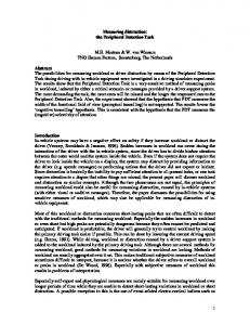
Figure 2.1: Multi-electrode array in regenerative paradigm: A shows headcap implantation on the rat cranium. B shows the ends of transected sciatic nerve sutured to the nerve guide tube mounted with the electrode array. C. Light micrograph showing top view of 18 electrode array mounted in a microrenathane based nerve-guide tube. D: Schematic of entire surgical procedure is shown where electrodes were placed in sciatic nerve and interconnecting lead wire is passed subcutaneously. Schematic of acute injury model is shown in E whereas F shows a chronic injury model. Scale bar (C) = 2mm.
17
bifurcation point, its proximal and distal ends were introduced into opposite ends of the conduits securing it with 10-0 ethylon suture to facilitate end-to-end repair seen in 2.1B. The fascia and the skin were closed in layers with resorbable (6-0 chromic gut) and nonresorbable (6-0 silk suture) sutures respectively. At the completion of the surgery, antipamezole (1mg/ml) was used to retrieve animal from the anesthetic condition. Study was performed in two injury models- acute and chronic injury models. In acute injury model, nerve was transected followed by immediate electrode implantation as schematically described in 2.1E; whereas in chronic injury group, following the nerve transection, proximal end was sutured to the adjacent muscle. Approximately after six months of injury, procedure similar to acute implantation was done as shown in 2.1F. Post operative care included oral doses of thimerosal (TMS), subcutaneous injection of bruprenex and topical application of bitter end. Conventional chip bedding was replaced by cellu-dri bedding to prevent mechanical injury to the animals. Animals were kept in humidity/temperature controlled room with 12 hour light/dark cycle with constant supply for chow-chow and water. 2.2.3 Sample preparation After the completion of survival period, perfusion was done with saline followed by 4% paraformaldehyde (PFA). The implant was harvested and the regenerated tissue was carefully isolated from the electrode array. Further, tissue was fixed overnight in 4% PFA. The proximal and distal nerve ends were marked with a dye and then embedded longitudinally in paraffin wax for further processing. The horizontal and coronal
18
(represented by a and b respectively in Fig 2.2A) paraffin sections of 6µm thickness were obtained and mounted onto capillary-gap charged slides (lilac-Fisher). 2.2.4 Immunohistochemical analysis Sections were deparaffinized with three changes of xylene followed by rehydration in descending grade alcohol and then wash with distilled water. Then the sections were blocked with endogenous peroxidase with 3% H2O2 in distilled water followed by universal blocking agent. Sections were then washed, incubated in primary followed by secondary antibodies. Primary antibodies used: S100 (for Schwann cells, 1:300 dilution, polyclonal rabbit anti-cow- DAKO Z0311); Mouse anti-200 KD neurofilament protein (for axonal profiles 1:300 dilution- Dako M0762); mouse antiED1 (for activated macrophages; 1:50 dilution-Chemicon); mAB MBP (for myelination). DAB solution was used as a substrate. Hematoxylin treatment followed by ammonia water was used as a counter-stain. 2.2.5 Immunofluorescence staining Paraffin sections were deparaffinized with 3 changes of xylene, rehydrated in descending grade alcohol and then washed in distilled water. Sections were blocked with 5% normal goat serum (GIBCO) mixed in 1% triton X-100 (Sigma) made in phosphate buffered saline (PBS) for one hour at room temperature followed by overnight application of primary antibodies diluted in blocking buffer at 4oC. The following day, sections were washed and secondary antibodies were applied for two hours at room temperature. Mounting was done using vectashield containing DAPI (Vector Labs, CA) to stain nucleus. All the primary antibodies were purchased from Chemicon, Temecula,
19
CA and secondary antibodies from Jackson ImmunoResearch Laboratories, West Grove, PA. Table 2.1 List of antibodies used with their concentrations Antigen Neurofilament protein (rabbit anti-NFP )/ ED-1(mouse antiED1) B-tubulin (mouse anti b-tub/S100 (rabbit anti-S100) Myelin Basic Protein (rat antiMBP) /ED-1 (mouse anti-ED1) Myelin Basic Protein (rat antiMBP)/ calcitonin gene related peptide (rabbit anti-CGRP
Tissue specificity Axonal profiles/ activated macrophages Axonal profiles/ Schwann cells Myelinated axons/activated macrophages Myelinated axons/ trkA+ pain fibers
Primary Concentratio n 1:100/1:500
Secondary Concentratio n 1:250/1:500
1:50/1:250
1:400/1:500
1:50/1:500
1:400/1:500
1:50/1:1000
1:400/1:1500
2.2.6 Electrophysiological studies The neural data acquisition system (PBX216WB450 2005, Plexon, Dallas, TX) was used to record neural activity from regenerating axons in a freely moving animal every week. This 16-channel recorder has a theoretical capacity to record from 64 neurons simultaneously i.e. four per channel at 25 second precision. Signals from the head stage consisting of field effect transistors (FET) with unity gain were routed by bus connector to be amplified and digitized by Plexon’s data acquisition unit. By visual inspection of analog signal on oscilloscope (Tektronix, DSA 8200) and digitized signal on the recorder program (library 6.5, driver 7.4.0), voltage threshold was set. Only those events which crossed the set threshold were recorded and further processed using a data offline spike sorter program (OFSS, Plexon). Three component principal component
20
analysis (PCA) was used to isolate single units from the noise (Chapin 2004; Nicolelis and Ribeiro 2002). All the channels had independent control over gain, filter frequency cut-offs and reference to maximize the extraction of information from the neuronal activity. 2.2.7 Behavioral studies Nociceptive recovery in rats with chronic and acute axotomy was evaluated by eliciting pain in response to thermal stimuli using plantar heat equipment (Ugo Basile, Varese, Italy). Animals were placed in a plexiglass chamber and allowed to stabilize for 15 minutes before applying the heat stimulus. Source of infrared beam was positioned under the plantar surface of the hind paw and a photocell (7370-372EW01) detects time from which the heat stimulus is applied until paw withdrawal. This time period was marked as paw withdrawal latency (PWL) that indicates the nociceptive threshold with 0.1 sec precision. Second reading for the same paw was not tested within an interval of 10 minutes to avoid response due to anticipation (Romero et al. 2007). Also tactile perception recovery was evaluated in the paw using a anesthesiometer (Ugo Basile, Varese, Italy), in which a gradient force is applied by a filament to the paw. Force and time after which paw was withdrawn was noted. Motor function recovery was evaluated in a rat sciatic nerve model by using toe spread assay. It is a natural instinct of an animal to stretch its toe when it is suddenly lifted up. Images of the injured left and normal right paw for all the rats were captured using camera (Panasonic, AG-EZ30) from a fixed distance when the rat was lifted up.
21
Toe spread index was calculated by taking ratio of distances between the first and fifth toes of injured to non-injured leg. 2.2.8 Imaging and quantification Quantification of proximity of the NFP+ regenerated axons from the active site was done using Axiovision application (Carl Zeiss, Axiocam, version 5.07.03). Light micrographs of all tissue-electrode interfaces of horizontal view were obtained and distance between axon and electrode edge was measured. For quantifying the extent of inflammation for each animal in a group, light micrographs of all electrode interfaces were obtained and spatial distribution of ED1 immunoreactive region was measured in four different areas A, B, C and D (shown in Fig 2.2B).
A
B
Figure 2.2: Method for quantifying extent of inflammation: A shows the schematic of electrode-conduit assembly with planes of sectioning; B is a schematic of a tissueelectrode interface (yellow-electrode; brown-macrophages). Axial immunoreactivity was quantified by measuring the lengths of positive stained areas in four directions. Carl Zeiss 510 laser scanning microscope was used to take low and high magnification pictures for immunofluorescent studies, with the probe-site centered in the field. Quantification of the fiber growth in proximal, middle and distal portion of the 22
regenerated tissue in each of the animal was done using LSM510 image examiner software (Carl Zeiss, version 3,2,0,115). Optical densitometry method was used in which double-level thresholding to eliminate saturation and background was done (Romero et al. 2007; Romero et al. 2001). Then the boundaries of positively stained area were marked and the total area in square micrometers, consisting of density profiles lying within cut-off window was measured. 2.2.9 Morphological Analysis of Muscle Gastrocnemius muscle from experimental and unoperated leg was harvested and their fresh weight was measured. The tissue was then snap- frozen in iso-pentane precooled in liquid nitrogen to -160oC. Cross sections (10µm) were then stained for acetocholinesterase receptors at neuromuscular junctions using non-specific esterase method (Stoward 1991). This method works under principle of hydrolysis of naphthol derivatives
(alpha-naphthyl acetate) and utilization of azo dye
(hexazotised
parasosaniline) which acts as capture agent to produce insoluble products at the site of enzyme activity. Briefly, slides were incubated in NSE incubation media made of mixture of NSE substrate solution, hexazotised pararosaniline and phosphate buffer for 40 minutes at 37oC. Slides were then washed in running water for 10 minutes, dehydrated in ascending grade alcohol and then mounted with cytoseal (TSRH manual, policy no CPH016). 2.2.10 Statistical Analysis All tissue-related data is reported as the mean±standard deviation and mean±standard error of the mean (SEM). An unpaired two-factor student’s t-test for
23
unequal variances was used to determine statistical difference between two means. p values less than 0.05 were considered to be significant. 2.3 Results Eight of ten rats survived the surgery and remained healthy throughout the study. No signs of self-mutilation of the hind limbs were observed in any of the animals after the nerve gap repair surgery. 2.3.1 Evaluation of regenerating axons through the electrodes Regenerated nerve covered the entire lumen of the conduit as shown in 2.3A. This was typical for most cases except for two where regenerated tissue was found covering only the electrode area. In all the harvested implants, regenerative conduits were covered by vascularized fibrous tissue. Robust nerve regeneration was observed in both the acute and chronic injury groups with 10-12 electrodes in contact with regenerated neural tissue. Regenerated neural tissue covered the entire shank of the electrode. Tissue-electrode interfaces which appeared after removal of the electrodes from the regenerated tissue are shown in Fig 2.3B harvested from an acute injury animal with 19 days of implantation. To distinguish between region of scarring, connective tissue encapsulation, inflammatory region, necrosis or apoptosis also to study various cell interactions around the foreign implant, histochemical analysis was performed. Regenerated axons positively marked by neurofilament protein were found to be in close proximity to the electrodes. (approximately 10-150 µm) in both the experimental groups. The electrodes did not seem to obstruct the regenerating axons. Fig 2.3 shows immunoreactive regions for neurofilament after immunoperoxidase staining in acute injury group (C-low and D-high
24
Figure 2.3: Robust axonal regeneration around the electrodes is demonstrated: Gross anatomical picture of regenerated nerve within the electrode-conduit assembly in case of acute end-to-end repair is shown in A. B shows a light micrograph of regenerated tissue detached from the conduit where white arrows are pointed towards the tissue-electrode interfaces. Low (C) and high (D) magnification light micrograph shows positive immunoreactivity for neurofilament 200KDa, a specific marker for axons indicated by the dark brown regions in close vicinity to the electrode site in case acute injury group. Asterisk represents the position of the electrode. Scale bars= 2.5 mm in A, 1mm in B, 100µm in C and E; and 30 µm in D and F. magnification). However meticulous quantification of proximity of axons from the periphery of the electrodes indicated that axons were closer to the electrodes in case of acute injury group (12.13±3.03 µm) compared to chronic injury group (28.28±12.18 µm) with the statistical significance of p