more powerful than ER. Middle level (ideal relational). DBMS-independent tables. I +. Placement of tables within files. Length of names. Domain definitions.
Edgar H. Sibley Panel Editor
Of the many approaches to relational database design, the Object Modeling Technique (OMT) is particularly effective. A comprehensive explanation and two applications show the semantic improvement of OMT over other approaches.
RELATIoNdL DATABASE DESIGN USING AU OBJECT-ORIENTEDMETHODOLOGY
MICHAEL R. BLAHA, WILLIAM J. PREMERLANI and JAMES E. RUMBALIGH
Object-oriented concepts provide a useful abstraction for relational database design. In this article, we present a design technique that has been used for several projects at General Electric. The methodology is intuitive, expressive, and extensible. Object modeling promotes adherence to normal forms and improves integration between databases and applications. Data’basedesign or data modeling is one aspect of software engineering. A data model is the first design step towards using a database in an application. It defines the structure of a database. For a relational Database Management System (DBMS), this structure includes details like defining attributes and tables and specifying rules to guarantee the integrity of tables. Applicatians populate the database structure and make the information accessible to the user. The goal of database modeling is to design a better database. The merit of a database design can be measured in a variety of ways. Some important criteria are: 1. performance: Does the structure of the database promote the availability of the data?; can users quickly retrieve and update relevant data?; 2. integrity: To what extent does the database guarantee that correct data is stored? (the definition of “correct” depends on the application); 01988 ACM OOOl-0782/88/0400-0414
414
Communications of the ACM
$1.50
3. understandability: How coherent is the structure of the database to end users, other database a.rchitects, and the original designers after a period of time?; and 4. extensibility: How easily can the database be extended to new applications without disrupting ongoing work?. We have developed a new approach to relational database design that has been effective in meeting these goals. This approach is based on the work of Loomis, Shah, and Rumbaugh [5]. We only focus on relational database design. Relational DBMS have a better theoretical foundation than network and hierarchical systems and are the focus of intense commercial activity. RELATED
WORK
There are many approaches to database design. Wiederhold, for instance, lists eleven categories of database models in his study [lo]. Although a thorough review of data modeling techniques is beyond the scope of this article, some of Wiederhold’s comments are apt. “We believe that having a wide variety of [database] models is valid, since an equally wide variety of objectives is being served . . . . Choosing a good way to represent a problem is a major step toward its solution” [lo, p. 115, 1161. The model presented here is particularly effective for large, complex database problems: often
April 1988
Volume 31
Number 4
Computing Practices
found in science and engineering. We will limit our discussion to the best alternatives to our methodology. Simples Tables (SQL Language)
The first question that arises is why should a data modeling technique be used in the first place? Why not just directly express the database structure in a DBMS language like SQL? Software engineering addresses this question. SQL has undergone extensive human factors studies and is one of the better DBMS languages in the commercial marketplace, just as LISP, Ada, and C are some of the better programming languages. Just as one would quickly dismiss the idea of immediately writing ‘C’ code, however, one must dismiss the temptation to begin with SQL code. The up-front planning, analysis, and design are an integral part of an effective data model. Chen’s Entity-Relationship
Model (ER)
The entity-relationship (ER) approach [l] is the most widely accepted technique for logical data modeling. The ER model supports entities and relationships. An entity is something that exists and is distinguishable. A group of similar entities form an entity set. A relationship is a logical binding between entities. Entities and relationships are described by attributes. ER diagrams are more expressive than mere tables. Relational tables are attractive vehicles for implementing a data model because they are simple, theoretically sound, understood, and supported by commercial DBMS. Nevertheless, the simplicity of relational tables interferes with designing a data model. Higher levels of abstraction, such as ER diagrams, are conducive to creative thinking and effective communication. Despite its usefulness, the ER method fails to fully capture the data modeler’s intent, especially for large, complex applications. ER lacks a substructure for entities and relationships. An even more powerful modeling tool is necessary. This claim is evident from research that supports extension or replacement of the ER method [lo]. So far, however, none of these techniques has matched the popularity of the ER method. Apparently, the other techniques do not satisfy the need for power beyond ER. Teorey’s Logical Relational (LRDM)
Design Methodology
Scores of papers have been written on variations of the ER method. We have selected Teorey’s approach as representative of state-of-the-art. Teorey and coworkers extend the ER approach with their Logical Relational Design Methodology (LRDM) [9]. LRDM, similar to ER, is a graphical data modeling technique that supports four basic concepts: entities, generalization, aggregation, and association. These terms will be defined later. For now, it suffices to say that the additional concepts improve the expressive power of LRDM. ER is a vast improvement over simple tables. Similarly, LRDM is more powerful than ER.
April 1988
Volume 31
Number 4
The Object Modeling
Technique
(OMT)
The Smalltalkprogramming language [3] demonstrates many object oriented concepts. An object-oriented program encapsulates data with procedures that act upon the data. Each package of data and operations is called an object. Objects cleanly separate external specification from internal implementation. An object affects other objects only through its external protocol. Objects are grouped to facilitate reuse of similar code. Object technology is most appropriate for complex, deeply structured problems. Object-oriented data models share many of the characteristics and benefits of object-oriented programs. A database stores the passive component of objects-that is, their private data or internal state. Applications combine this data with an active component-the procedures or operations. The Object Modeling Technique (OMT) improves upon the ER and LRDM approaches. One advantage of object-oriented data models is the straightforward integration with object-oriented programs. In general, it is difficult to meld database interaction with procedural code. The use of a common object metaphor and the same design notation for data models and programs helps this situation. APPLICATION OF THE OMT DATABASE DESIGN Three Levels of Representation
TO RELATIONAL
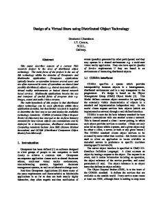
Figure 1 summarizes our database design methodology. This methodology uses three levels of representation. We will refer to them as the high, middle, and low levels. All three levels describe the same problem at different levels of abstraction. The initial, logical data High level (abstraction) Logical data model
+ I + I
Mapping of object structures to tables Candidate keys No-null attributes Domains Frequently accessed attributes
Middle level (ideal relational) DBMS-independent tables
Placement of tables within files Length of names Domain definitions Primary keys Secondary indexes
Low level (reality) Actual DBMS data definition commands
FIGURE 1. Three levels of Representation
Communications of the ACM
415
Computing Practices
model is successively converted into ideal relational tables and then into DBMS data definition commands. Multiple levels are a useful construct for encouraging logical database design while still addressing implementation realities. The high level focuses on the fundamental data structure. The high level is a subset of a graphical notation th.at was developed by Loomis, Shah, and Rumbaugh [5] for object-oriented programming. They call their notation the Object Modeling Technique (OMT). The authors of this paper do not take credit for developing the OMT. We have taken the OMT and extended it into the realm of databases. An object-oriented database design presents a simple and concise logical abstraction of data that is straightforward to implement with a commercial DBMS. We found that non-DBMS application experts were able to read OMT diagrams after a few hours of explanation. The middle level contains generic, DBMS-independent tables. The motivation for the middle level is to decouple the general problem of mapping objects to tables from the idiosyncrasies of each DBMS. The middle level is wordier and less effective at conveying the overall structure of the model than the high level but documents more details. The middle level addresses issues such as the mapping of object structures to tables, domains, and keys. The low-level is the data definition language of the target DBMS. This level contains the actual DBMS commands that create tables, attributes, and indexes. The low-level considers DBMS-specific details such as placement of tables within database files, a limited set
Pump
Representation
An object is a thing that exists and has identity. Examples of objects are items such as the chair in the corner, room 101, and George Washington. A group of similar objects form an object class. Chair, room, and people are examples of object classes. An object is an instance of an object class described by attributes or fields. The notion of an object is synonymous with entity in the ER and LRDM methods. The boxes in Figure 2 denote object classes. The equipment class has equipment name, cost, and weight fields. Pump has suction pressure, discharge pressure, and flow rate fields. Relationships A relationship is a logical binding between objects. There are three types of relationships: generalization, aggregation, and association. We indicate a relationship with a line or lines between objects. Special symbols at the ends of a relationship line indicate how many objects of one class relate to each
Surface area Tube pressure Shell pressure Tube diameter
Pump type
Diaphragm pump Impeller diameter Number of blades Axis of rotation
High-Level Objects
Heat exchanger
Suction pressure Discharge pressure Flow rate
A
of data types, and choice of performance tuning mechanisms. It also deals with the arbitrary restrictions such as size limitations. The mapping between levels is mechanical except for that presented in the two boxes in Figure 1. These boxes contain decisions that the data modeler must make during the mapping process. We perfor:med most of the conversion manually, but an automatic conversion is possible.
Diaphragm material
. . .
Plunger pump Plunger length Plunger diameter Number of cylinders
FIGURE2. Generalization Relationship
416
Communications of the ACM
April 1988
Volume 31
Number 4
ComputingPractices
Car Name Year Color
CAR-DOOR
CAR-ROOF
Number of windows
FIGURE3. Aggregation Relationships
Company Name Address
WORKS-FOR
Job title
3 Name Social security number Address
MANAGES o
FIGURE4. Association Relationships
object of another class. We call this the multiplicity of the relationship. For instance, a small solid circle means many. Many, in this context, is zero or more. A small hollow circle means zero or one. A straight line ending without a symbol denotes exactly one. The ER method uses the term relationship in a different and much narrower sense than LRDM and OMT. The ER relationship is equivalent to the association relationship of the LRDM and OMT. The ER method has no construct that corresponds to generalization and aggregation. Generalization Relationship
A generalization or is-a relationship partitions a class into mutually exclusive subclasses. Generalization may have an arbitrary number of levels. The heavy triangles in Figure 2 symbolize generalization. A piece of equipment can be a pump, heat exchanger, tank, or something else. Pumps subdivide into centrifugal, diaphragm, plunger, and other. For the top generalization, equipment is the superclass; pump, heat exchanger, and tank are subclasses. The superclass stores general data like name, cost, and weight. The subclasses store data particular to each type of equipment. Similarly, for the lower generalization, pump is the superclass while centrifugal pump, diaphragm pump, and plunger pump are subclasses. Each box in Figure 2 corresponds to an object class. Each box does not correspond to an object. The same object is being represented at each level of the generalization. Existence dependency holds; a pump cannot be entered into the centrifugal pump table unless entries are also made in the pump and equipment tables. Attri-
April 1988
Volume 31
Number 4
butes are inherited from the top level down. Each centrifugal pump has an equipment name, cost, weight, suction pressure, discharge pressure, flow rate, impeller diameter, number of blades, and axis of rotation. Note that the OMT supports multiple inheritance. Each object may participate in more than one generalization hierarchy. Aggregation Relationship
Aggregation is an assembly-component or a-part-of relationship. One well known example of this relationship is the “bill-of-materials” or “parts explosion” problem. Aggregation combines low level objects into composite objects. Aggregation may be multilevel and recursive. For example, a data structure may recursively refer to itself. As shown in Figure 3, a roof is a part of a car; many doors are part of a car. The same type of door and roof can be used for a variety of cars. In this case, car is an assembly and door and roof are components. Note that the arrows point towards the composite object. Aggregations often exhibit existence dependency. Association Relationship
An association relates two or more independent objects. Associations do not exhibit existence dependency. Figure 4 shows that many employees work for a company and an employee manages other employees. We arbitrarily restricted an employee to working for one company. In some contexts, multiple companies may be more appropriate. The precise choice of objects, relationships, and multiplicity of relationships depends on the problem domain. Associations may have one or more properties. These are circled in the diagram.
Communications of the ACM
417
Computing Practices
Qualification
of Relationships
Qualification adds information about the many end of a relationship. Figure 6 presents an aggregation, with and without qualification. A plant has many pieces of equip:ment that are distinguished by equipment name. Equipment name is a qualification field. Either form, qualified or unqualified, supports storage and retrieval of equipment data. The notion of qualification refines the notation. Qualification has two benefits: improved semantic accuracy and more visible navigation paths. Both forms state that a plant has many pieces of equipment, however, t.he qualified form adds a unique name to each piece of equipment in a given plant. To find a piece of equipment, we first choose a plant and then specify an equipment name. Qualification is a major advange of the OMT approach. Qualification frequently occurs and is worthy of special semantic support.
I
Plant
second normal form. Earlier, we defined objects as things that exist and are distinguishable. Objects have a unique key when provided with the distinguishing information Relationships are between objects. Thus relationships also have a unique key-the combined keys of participating objects. Our claim for third normal form is a bit weaker. Most violations of third normal form seem to occur when extraneous information is introduced into a table or a table lacks focus. Relational tables allow unrealistic constructs and are at too low a level for design. The object paradigm is at a higher level of abstraction and tends to block unreasonable designs. Objects are less flexible and less dangerous than relational tables. Building a data model from a small number of coherent entities is superior to the traditional approach of collecting all the attributes, ferreting out the functional dependencies, and synthesizing tables.
Plant
I
q
Plant name Supervised by
Equipment name
Not qualified
Qualified
FIGURE 5. Aggregation Relationships
410
Middle Level Representation
Objects
The middle level maps high-level object structures into generic tables. The middle level decouples the general problem of mapping objects to tables from the idiosyncrasies of a DBMS. This improves documentation and easesporting to a new DBMS. In our applications we have observed that the resulting tables tend to be in third normal form. Third normal form is an intrinsic benefit of object modeling. Normal fo.rms improve data integrity. A table is in first normal form when each attribute value is atomic and does not contain a repeating group. A table is in second normal form when it satisfies first normal form and each row has a unique key. A table is in third normal form when it satisfies second normal form and each non-key attribute directly depends on the primary key. One meets first normal form by decomposing complex objects. The extent of this decomposition depends on the meaning of atomic and the application. For example, it may be perfectly reasonable to consider an array an atomic object when it stores the composition of a fluid. In a different context, however, an array may require decomposition. It is ‘easyto see why object-derived tables satisfy
Each object class maps directly to one table. .A11object fields become attributes of tables. Note that Figure 6 introduces an additional attribute: “Plant ID”. Our data modeling methodology provides strong suppa’rt for the notion of object identity [a]. Each object has a unique ID; all references to objects are made via the ID. Object identity is implicit in object diagrams and must be made explicit in tables. There are many reasons for adopting a strong sense of object identity. One advantage is that object :IDs are immutable and completely independent of changes in data value and physical location. The stability of object IDS is particularly important for relationships since they refer to objects. Contrast this with referring to objects by name. Changing a name requires update of many relationships. Object identity provides a uniform mechanism for referencing all objects. The middle level controls the use of null values. Null means that an attribute value is unknown or not applicable for a given row. “N” forbids nulls; “Y” permits them. Attributes in candidate keys must not be null. This column gives the data modeler the optia’n of requiring values for additional fields.
Communications of the ACM
April 1988
Volume 31
Number 4
Computing Practices Middle level
High level
I Attribute
name
1 Nulls?
Candidatekeys: (Plant ID) Frequentlyaccessed: (Plant
1
Domain
(Plant name) ID) (Plant name)
FIGURE6. Middle Level for an Object
Each attribute has a domain or set of legal attribute values. It would be undesirable to give “plant name” a domain of long name in one table and short name in another. Consistency is important. Domains ensure consistent decisions on attribute length and prevent operations on incompatible entities. It does not make sense to add a cost to a weight. The concept of domain is similar to strong typing in a programming language. Figure 6 lists candidate keys. A candidate key is a set of attributes that uniquely identify each row. Each attribute may belong to zero, one, or more candidate keys. Figure 6 also lists groups of attributes that are likely to experience frequent access. These groups would be prime targets for indexing or hashing. We would expect IDS and names to be common references. The order of the attributes within a group may or may not be relevant to the low level implementation.
Generalization Relationship
A generalization relationship has one superclass table and multiple subclass tables. Figure 7 illustrates the general mechanism. For each piece of equipment, there is one superclass row and one subclass row with a common Equipment ID. Recall that literally the same object is being represented at each level of the generalization. Equipment type is the superclass discriminator field that partitions the subclasses. Each value of equipment type corresponds to one subclass table. Aggregation Relationship
Many-to-many relationships by necessity map to distinct tables. This is a consequence of normal form. Oneto-one and one-to-many relationships may be mapped to distinct tables or merged with a participating object. Our handling of one-to-one and one-to-many aggregations depends on the context. We merge existence de-
I High level
! I
Equipment
i
Equipment name cost Weight
I
h
Equipment
type
I I i
I
I I
Equipmeni
Attribute name
Nulls?
Domain
Equipment ID Equipment name Equipment type cost Weight
N N N Y Y
ID Long name Equip type Dollars Weight
Candidatekeys: (Equipment ID) Frequentlyaccessed: (Equipment
(Equipment name) ID) (Equipment name)
Candidate keys: (Equipment ID) Frequently accessed: (Equipment
ID)
FIGURE7. Middle Level for a Generalization Relationship
April 1988 Volume 31 Number 4
Communicationsof the ACM
419
Computing Practices
pendent aggregations with an object table to simplify integrity enforcement. Within the context of the application for Figure 8, every piece of equipment must be assigned to a plant. Freestanding aggregations are stored in distinct tables. In Figure 9, each type of roof is used for several car models. A roof is a part that exists independent of any particular car.
Low-Level
Representation
The low-level is the data definition language of the target DBMS. This level contains the actual DBMS commands that create tables, attributes, and indexes. This level exploits DBMS features and compensates for shortcomings and quirks. The specific details of the low level depend upon the choice of target DBMS. MIMER was the DBMS for the two applications that we will discuss later and will be the basis for discussion in this section. MIMER is an SQL-like, relational DBMS [6].
Associrztion Relationship
As a rule, we map associations to distinct tables, as in Figure 9. Properties of an association become attributes of the association table. We do not collapse associations with a corresponding object, as in Figure 8, except for performance bottlenecks. There are many reasons for externalizing associations. They are as follows: 1. Associations are between independent objects of equal syntactic weight. In general, it seems inappropria.te to contaminate objects with knowledge of other objects; 2. collapsing associations with descriptive properties into objects may violate third normal form; 3. it is difficult to get multiplicity right on the first few design passes.Choice of multiplicity is sometimes a rath.er arbitrary decision and may change as the subset of the world being modeled evolves. One-to-one and one-to-many associations may be externalized. Many-to-many associations must be externalized; and 4. a symmetrical representation simplifies search and update.
Prima y Keys
MIMER requires that each table have a primary key composed of one or more attributes. This desirable feature improves the integrity of MIMER databases. The primary key must be unique. None of the participating fields may be null. MIMER sorts each table on its primary key. The primary key is the fastest access path to a MIMER row. The middle level identifies candidate keys. One candidate key must be chosen as the primary ke:y. In general, our philosophy would be to use the object ID as the primary key for object tables. The primary key for relationship tables would be one or more IDS from participating objects. Unfortunately, MIMER interferes with this approach. We deliberately chose to make IDS the primary key even though they have no inherent meaning to the user. Most scientific applications are structurally com-
Middle level, merged tables
I
High level
Attribute
name
I Nulls?
I
Domain
I
Plant
I
Plant
I
Plant name Supervised by
I
1
1 Equipment na&T
! /
Candidatekeys: (Plant ID) Frequently accessed: (Plant
Attribute Equipment Equipment cost Weight
name
Equipment ID Plant ID Equipment name cost Weight
(Plant name) ID) (Plant name)
Nulls? N N N Y Y
ID ID Long name Dollars Weight I
i I
Candidatekeys: (EquipID) (Plant ID, Frequentlyaccessed: (EquipID) (Plant
Equipname) ID, Equipname)
FIGURE8. Middle Level for an Existence-Dependent Aggregation
420
Communications of the ACM
April 1988 Volume 31 Number 4
Computing Practices
Middle level, distinct tables
Car
i High level
I Candidatekeys: (Car ID) Frequently accessed: (Car
Attribute
(Name, year) ID) (Name) (Year)
name 1 Nulls?
1
Domain
1
CAR-ROOF
Candidate keys: ( Roof ID ) Frequently accessed: (Roof ID )
~1 Car-Roof
I
Candidate keys: ( Car ID ) Frequently accessed: (Car ID)
(Roof
ID)
FIGURE 9. Middle Level for a Free-Standing Aggregation
plex and difficult for the unassisted user to navigate. Furthermore, commercial DBMS lack proper support for integrity (specifically referential integrity [2]). Thus, complex applications must mediate user access with custom programs. If we are going to restrict database access through a program, we might as well do our access through IDS. IDS never change and they have a small fixed size (that can be implemented as an integer) that speeds selects and joins. Secondary Indexes
MIMER is deficient in its support for secondary indexes. Secondary indexes in most relational DBMS serve a dual role. They improve the performance of some queries by quickly finding the rows with a certain attribute value. Secondary indexes can also enforce the uniqueness of candidate keys. The problem is that MIMER restricts secondary indexes to a single attribute. This provides adequate performance but it damages integrity. MIMER secondary
April 1988
Volume 31
Number 4
indexes cannot enforce the uniqueness of multiattribute candidate keys. Only primary keys may be multiattribute. To compensate for this anomaly, we were forced to compromise some choices of primary key. An example may clarify this point. In Figure 8 for the equipment table, we wanted to make “Equipment ID” the primary key. “Plant ID” + “Equipment name” becomes a unique secondary index. This satisfies our desire for object identity and meets candidate key and performance specifications. Since MIMER does not support a unique secondary index, we were forced to compromise. Our ultimate decision was to make “Plant ID” + “Equipment name” the primary key and “Equipment ID” a unique secondary index. This example illustrates some of the value of our multilevel modeling approach. The middle level enables us to clearly indicate our intent. The low-level generates executable code. A future software port to another DBMS with different features and problems will be more likely to honor our original intent.
Communications of the ACM
421
Computing Practices
principles of good software engineering. We ;are left with the ER, LRDM, and OMT for further discussion.
Other Details h4IMEIR regards a database as a collection of files. Each table is wholly contained within one file. The low-level assigns each table to a file. MIMER restricts names to a maximum of eight characters. One must specify a h4IME:R name for each table and attribute. MIMER provides some support for domains. Data modelers can assign data type, data length, default value, range check, and edit mask to domains.
Shortcomings
of Chen’s ER
The entity-relationship (ER) method has certainly been a useful and successful technique for database design. The ER method, however, leaves much room for improvement, especially in certain problem domains. ER lacks a substructure for entities. It has no counterpart to generalization hierarchies. Generalization allows one to refine the structure of entities and add detail as needed. One can choose the proper level of abstraction for each context. The resulting design is robust and extensible. Generalization and its extension to programming is the fundemental idea in objectoriented languages like Smalltalk, C++, and Objective C.
ANOTHER LOOK AT ALTERNATE METHODOLOGIES
Now, let us revisit our comparison of data modeling techn:iques. Recall that we reject the idea of directly designing a database with a DBMS language like SQL. A DBMS language is at too low a level and violates the
I
Site Location name Plant name @
a
Plant version Creation time Last update time Comment Section name
I
I
Equipment type
I
I
. . .
Heat exchanger Suction press Discharge press Flow rate
Surface area Tube pressure Shell pressure Tube diameter
R
Height I
FIGURE 10. Application 1, Aggregation Hierarchy
422
Communications of the ACM
April 1988
Volume 3:f
Number 4
Computing Practices
Generalization reduces the semantic gap between the data modeler and the database design language. Similarly, it reduces the semantic gap between the data model and applications. The addition of generalization to ER is a substantial step forward, in the same way that ER was from database languages. ER also lacks a substructure for relationships. Whereas ER only offers association, newer approaches support aggregation and association. For many database problems, the ER approach is sufficient. For many database problems, it would be the method of choice. Many design productivity products are available in the commercial marketplace to assist the ER data modeler. The ER approach has had the benefit of close scrutiny and much research. For large, complex problems, however, ER lacks power. Scientific applications are pushing the frontier of database research, and this requires all the help that is available. The two applications in the next section required about 20 dense pages of OMT diagrams and six months of database design work. It is not difficult to envision several hundred pages of OMT diagrams taking several years for more complex projects. A more effective tool directly affects the quality of the resulting design and the effort expended. Comparison of OMT with Teorey’s LRDM In their article, Teorey [9] and coworkers claim that their LRDM approach improves upon the ER method. We agree. LRDM has generalization and it has aggregation. Our OMT-based approach builds upon LRDM as follows: 1. Qualification further refines the structure of relationships; 2. the OMT directly extends into the realm of programming. (The OMT supports methods.) The OMT provides a consistent notation for database models and application programs; 3. the OMT graphical syntax appears to be cleaner than that of LRDM; and 4. an intermediate level between high level database design and a DBMS language is provided. This is more flexible than Teorey’s direct mapping between graphical diagrams and a DBMS language. Our work emanates from an industrial environment and has been refined by use on real problems. Our experience with database design cannot match that of the ER approach, but it is still significant. About 12 people have influenced the evolution of the OMT. More than one hundred have been trained in its use. APPLICATION OF THE METHODOLOGY These OMT applications were performed by two different people. The intent is to convey some measure of the size and complexity of these applications. Description of the First Application The first application is a chemical engineering problem. The objective was to integrate the data from many freestanding programs that include drawing programs, de-
April 1988
Volume 31
Number 4
sign programs, simulation programs, and cost programs. Most of these programs already exist. Current practice at best relies on converting and passing files. This is awkward, since n x n interfaces are required for n programs. Current practice often degenerates into manual data reentry. The solution is to exchange data with a database rather than more data between each pair of programs. Then for n programs, one requires 2n interfaces. Most of these programs are mature, carefully debugged code and to tamper with them is undesirable. Thus, these programs must use database services in batch mode. A preprocessor extracts information from the database and generates an input file. The application program runs. Then a postprocessor digests the output file(s) and updates the database. The application remains unchanged and runs as before, unaware that it is receiving database services. The first application is dominated by four aggregation hierarchies: equipment, piping, graphics, and mathematical simulation. The bulk of the data model refines these hierarchies and forms associations between the levels of the hierarchies. Figure 10 shows the equipment aggregation hierarchy. A site name uniquely identifies a site. For that site, a plant name identifies a plant. The plant has multiple versions. Selecting a plant version and a section name locates a particular section. A section combined with an equipment name finds a piece of equipment. A piece of equipment may be a pump, heat exchanger, tank, or some other object. Description of the Second Application The second application focuses on electrical engineering. The goal was to develop an interactive graphical editor for electric power diagrams. Typical operations include creating, deleting, moving, copying, cutting, and pasting of buses, circuits, and devices. This program must run fast despite frequent interaction with a database during its course of execution. The database provides a neutral format for interfacing to other applications, crash recovery, and multiuser concurrency. As of this writing, we have designed the database. We are preparing to implement the procedural code. We will be using an in-house object-oriented language called DSM [?‘I that is built on top of C. This application decomposes a diagram into a series of sheets. Each sheet corresponds to one piece of paper upon output. Nearly all information can be assigned to a single sheet. This application runs in real time. It cannot pause for a database operation. We plan to boost performance by shadowing the database in memory. The user selects some sheets for study and the system reads them into memory. All read requests are satisfied through RAM data structures-a quick response. Update operations are accumulated in memory and posted to the database upon an explicit save request. This save request spawns an asynchronous process with a series of database commands.
Communications of the ACM
423
Computing Practices
There are three major components of the second application data model: a geometry aggregation hierarchy, a simulation model, and user interface. The bulk of the data model fleshes out the geometry and simulation subsections and relates the two. Figure 11 is a fragment of the geometry aggregation model. Buses and circuits have two ends. A device has an arbitrary number of pins. These possible points of contact generalize into a pin. We improve integrity and performance by associating pin with a connection rather than with other pins. This model can quickly answer the following types of questions: I.. What connects to the following electrical object?; 2. What connects to a particular pin on an electrical object?; and 3. What electrical objects connect at a screen location?.
Connection
on. So instead of storing material name, we store an ID or pointer into a table of material names. For 100 types of equipment there would be approximately 100 different references into a material list. This would skew the statistics. We felt that these references into a~material list were not of the same stature as associations between independent and freestanding objects. We should also comment on the multiplicity numbers. This issue arises for qualified aggregations and qualified associations. We counted the qualified aggregation between site and plant as one-to-many rather than the one-to-one shown in Figure 10. The ER approach, the traditional way of viewing data :models, does not qualify relationships. We felt that multiplicity statistics would have the most meaning if placed within the ER context. So, to summarize, we counted the mul-
Pin
-7
FIGURE11. Application2, ElectricPowerConnectivity
Application
Statistics
Table Xquantifies the complexity and diversity of the two applications. The statistics are purely a by-product of our application work. There was no deliberate attempt to warp the data models so the statistics would support a particular point. ’ The numbers in Table I are approximate. There is some subjectivity or discretion in how these statistics are compiled. The generalization fan-out for the first application is shown as 100. The equipment object in Figure 10 generalizes into many types of equipment: pumps,, tanks, columns, reactors, and so forth. There would be approximately 100 different types of equipment and hence about 100 subclass tables. We actually developed tables for two types of equipment. We counted 100 as the generalization fan-out and ttio towards the number of objects and tables. Table I does not count tables whose sole purpose was to remedy DBMS shortcomings and/or tighten integrity. An example may clarify this point. Each type of equipm.ent has one or more materials of construction. If the database stored material names, confusion could arise from abbreviations, synonyms, mistyping, and so
424
Communications of the ACM
TABLEI. ApplicationStatistics Appliition
-1 Total number of tables
2
71
108
Maximum attributes per table Total number of object classes Total number of relationships Distribution of relationship type: Qualified aggregation Unqualified aggregation Generalization Binaty, unqualiied association Qualified association Ternary association Distribution of relationship multiplicity: One-to-one One-to-many Many-to-many
100 48 66
50 82 45
21 18 4 20 1 2
11 1 7 25 1 0
5
44 ‘17
14 30 1
Maximum number of aggregation levels
6
4
Maximum levels below generalization symbol
1
1
100
50
Maximum generalization fan-out
April 1988
Volume 31
Number 4
Computing Practices
tiplicity for qualified relationships as if the qualification was not there. A site has many plants. Note the usefulness of qualified aggregation. The low count for generalization may be misleading. The large maximum fan-out is a better indicator of the importance of generalization. FUTURE DIRECTIONS Automate OMT-Based Database Design Currently, the transformation between levels is a combination of ad hoc tools and much manual effort. In the future we envision a fully automatic process. The data modeler draws OMT diagrams on the screen. The drawing software captures objects and relationships while actively supporting the semantics. Data flows forward to the middle and low-levels. In this scenario, the data modeler has an efficient, integrated data modeling tool. Tight control of redundant data enhances model integrity. A meta-data model and a DBMS lie at the core of such a system. Further Enrich the Semantic Support The OMT improves upon the ER and LRDM methods and provides richer semantic support. We see many opportunities for further improvements beyond that of the OMT: 1. versioning. Current databases are a snapshot of time. We also need the history of the data. We have made some crude attempts at capturing versions in our applications, but an elegant solution has been elusive; 2. accountability. Who provided the data? Who approved the data?; 3. data quality. How much confidence do we have in the data? This area becomes particularly murky as we combine data; and Appendix A. Textural format for object models A graphical model permits the designer to see the overall structure of an application at a glance and to easily trace out the relationships among various objects. Nevertheless, there are times when a linear textual format is useful, particularly when object classes have many fields or methods. It is also necessary to have a textual format if the object model is to be compiled for use with an object-oriented language or automatically converted into a database schema. The following examples are taken from the object-oriented language DSM (Appendix B). The authors and colleagues have implemented a graphical editor for the OMT which generates DSM declaration text as an output. A typical object class is declared with the format:
define fields
class
equipment
equipment-name:text cost:money weight:weight This class is implicitly
April 1988
Volume 31
a subclass of the predefined
Number 4
4. expert knowledge. How do we merge implicit knowledge with an explicit database? Knowledge based system are one answer, but they only handle small amounts of data. CONCLUSION Our OMT-based approach to database design has many advantages. It is: 1. intuitive, easy to use, and easy to understand. NonDBMS application experts were able to read OMT diagrams after a few hours of explanation; 2. expressive. It provides a richer set of constructs for modeling data than alternative approaches. 3. extensible. It accommodates changes in the scope of the data model and ports to other DBMS. 4. a useful level of abstraction. It matches real world problems well and maps naturally to a relational DBMS. 5. good performance. It is easy to visualize patterns of access to the data when using the OMT. 6. promotes database integrity. Object-derived tables tend to be in third normal form. 7. improves integration. The object paradigm helps bridge the semantic gap between databases and applications. 8. has been tested. The OMT has been applied to real problems. It has suffered critical review and several iterations of refinement. The OMT is evolving and maturing. This methodology is an improved version of that used for our past applications. Object modeling has improved the clarity of our thought and ability to communicate during the design process. At the same time, our application work has generated feedback to fine tune the methodology. This cycle continues. class objecf, the ultimate ancestor of all classes since no superclass has been specified. Each field has a name and a data type. The name must be unique within the class. The type declarations establish the domain of a data field. It is possible to declare a type as being objecf, in which case it can hold any kind of object. A type can specify a particular object class, in which case the object must be an instance of the class pr one of its descendent classes. A type need not be an object; for example, integer, boolean,or text are pure values, not objects. In this case, money and weight are user defined value types. Generalization relationships specify a superclass as part of a class declaration:
define task subclass fields diameter:length height:length
of equipment
Class tank inherits all the fields of class equipmenf plus two new ones of its own. A one-to-many aggregation is declared with the format:
Communications of the ACM
425
Computing Practices
ailed associations are declared in a similar ma C&P containa of only one car.
EiKh
‘. d by descendax% of he &as unles by another method with the same di@n to the class name and list c x can contam a list of methods , @list box. In IBM, each class declaration can d &tbti& StWion Of the following format:
the format:
fields The format is similar to the aggr tionship fields are values associate * .. #Z 4% r&l -El. .;. per .1 Field values are functionally dependetst.bn~~~.~~~: nent classes of the association, The fiel&‘eectmn is-~:: : optional; most associations do not have fiel~velnes, ” The multiplicity of a relationship can besRe&ied’by one of the following: *-* many-to-many *-I many-to-one f-* one-to-many l-l one-to-one Each component of an association can have an optional name to distinguish it from other components: define manages manager:employee employee
association I-* worker:
The component names managerand worker are called role names because they indicate the role that each component plays in the relationship. They are particularly useful for associations between objects of the same class. When objects are of different classes, class names serve to differentiate the components. A role name establishes a pseudo-field with respect to a class. For example, class empZoyeehas a pseudofield mlmager that yields an employeeobject and a pseudo-field worker that yields a set of employeeobjects. Unlike actual fields, the pseudo-fields generated by an association declaration are not independent; they are views on the relationship. A qualified aggregation is declared with the format: define aggregation plant [equipment-name:text] ment
l-l
equip-
In this case, equipment name qualifies a plant object to yield a unique piece of equipment; each pisce of equipment has a unique name within some plant, The role names for the plant and equipment have been omitted, as has the name for the relationship itself; a default relationship name is provided by the compiler. Quali-
426
Communications of the ACM
e?ch.method is implicitly an &dditional arguments are in v&e type must be specified. given to each argument. Meth$s ~~.~:im~rt~at .~,‘bbject-oriented programming. Database Sclmnnis tY$@c&llyomit any specification of the operations that are permitted on the data, in part because a database is supposed to hold data but not restrict its use, When model&g a database, we have nevertheless found it useful to consider and specify the operations that will be apblied to the data. Even if the operations will be implemented externally to the database, their specification permits the object model to be evaluated for logical completeness and correctness early in the design cycle. We have found the objectoriented paradigm useful for these specifications. Appendix B. D&t Structwre Manager IDSM) The Data Structure Manager (DSM) is a softw,are development system developed at GE-Corporate Research and Development and GE-Calma to support objectoriented programming in the C language. DSM implements all the concepts of a standard object-oriented system such as Smalltalk withii the context of the C language while adding a number of extensions that greatly extend its power, such as support for relationship& IBM comprises a set of preprocessors and a run-time object library w&ten in C. The user defines amobject class hierarchy with single or multiple inheritance and relationships between classes. Full metaclass hierarchy is supported including class fields and class methods. This is similar to Smalltalk. All system objects are ereated dynamically at run time and are fully extensible. The system manages memory but does not include a garbage collection scheme. Using class descriptor and relation descriptor objects, generic operations such as pretty printing, copying, destroying, and saving and restoring objects in a file are possible.
April 1988
Volume 31
Number 4
:
i : ;:~” _’;n nij
I_
oa~nbe called udng the tiur&me messagesearch mechagism btied on the dbject class ar called directly as a C futiction call if the object class is known. The DSM com$ler automates this decision in most cases. Object fields (instance variables in Smalltalk) can have C types as their values, so the overhead of objects is not necessary to hold pure values such as integers or structures of values. The object class hierarchy is a part of the C type hierarchy. This approach allows easy interfacing of DSM programs with existing non-DSM code written in C or other languages. DSM has been used for creating production software
Acknowledgments. We would like to thank Esin Ulug, Ashwin Shah, Mary Loomis, and the referees for their careful and constructive review of this document. REFERENCES 1. Chen, P.P. The entity-relationship model: Toward a unified view of data. ACM TODS I, 1 (Mar. 1976). 2. Date, CJ. Relational Database: Selected Writings. Addison-Wesley, Reading, Mass., 1966. 3. Goldberg, A., and Robson. D. Smalltalk-80: The Language and Its Implementation. Addison-Wesley, Reading, Mass., 1964. 4. Khoshafian, S.N., and Copeland. G.P. Object identity. In Proceedings of the ACM Conference on Object-Oriented Programming Systems, Languages, and Applications. (Portland, Oregon). SIGPLAN Not. 21,ll (1966). 5. Loomis, M.E.S.. Shah, A.V.S., and Rumbaugh, J.E. An object modeling technique for conceptual design. In Proceedings of the European Conference on Object-Oriented Programming. (Paris, France, June 1517). Lecture Notes in Computer Science, 276. Springer-Verlag, New York, 1967. 6. MIMER Information Systems AB. Uppsala, Sweden. 7. Rumbaugh, J.E. Data Structure Manager Reference Manual. GE internal document. Schenectady, New York, 1967. 8. Rumbaugh, J.E. Relations as semantic constructs in an objectoriented language. In Proceedings of the ACM Conference on Object-
JOURNAL OF THE ASSOCIATION FOR COMPUTING
MACHINERY
$W.OO/year for ACM members; $i%OO/year for nonmembers. Subscriptions
(Members please include member #)
in ~S~~~~fbut Bert be bootstrapped on a system that runs s&d&d C. It has been ported to several different systetip &&ding Sun/Unix, VAX/VMS, and Apollo/ Aegis workstations. The DSM system includes an object prettjr-pririter and an interpreter for displaying objects and data structures for debugging programs. The most significant novel feature of DSM as an object-oriented language is its support for relationships in both language syntax and run-time library [8). Users of the system have found relationships intuitive and. useful and have requested extensions to the language that have increased its power, such as the ability to treat relationships as pseudofields using role names.
Oriented Programming Systems, Languages, and Applications. (Orlando, Fla., Oct.). SIGPLAN Not. 22, 12 (1987). 9. Teorey, T.J., Yang, D.. and Fry. J.P. A logical design methodology for relational databases using the extended entity-relationship model. ACM Comput. Sure. IS,2 (June 1966). 10. Wiederhold. G. Modeling databases. Inform. Sci. 29, 2 (1983). CR Categories and Subject Descriptors: D.2.2 [Software Engineering]: Tools and Techniques; D.2.10 [Sonware Engineering]: Designmethodologies; H.2.1 [Database Management]: Logical Design: H.2.6 [Database Management]: Database Applications; J.2 [Physical Sciences and Engineering]: J.6 [Computer-Aided Engineering]:-computer-aided design General Terms: Design, Documentation Additional Key Words and Phrases: Entity-relationship method. normal forms. object, object-oriented, relational database Authors’ present Address: Michael R. Blaha, William J. Premerlani, and James E. Rumba@, GE, Corporate Research and Development, Schenectady, NY. Permission to copy without fee all or part of this material is granted provided that the copies are not made or distributed for direct commercial advantage, the ACM copyright notice and the title of the publication and its date appear, and notice is given that copying is by permission of the Association for Computing Machinery. To copy otherwise, or to republish, requires a fee and/or specific permission.
An excellent source to information on computer theory and research in.. Algorithm & complexity theory Artificial intelligence Combinatorics & graph theory Computer organization & design Systems modeling & analysis Database theory & structures Distributed computing Formal languages Computational models Numerical analysis 9 Operating systems and research Programming languages & related methodology Computational theory
Published four times a year (ISSN 0004-5411)
l
l
l
l
Write for an order form and your ACM Publications Catalog to: .
l
l
l
l
l
l
l
Catherine Yunqye, ACM, 11 West 42nd Street. New York, NY 10036
l
April
1988
Volume
31
Number
4
Communications
of the ACM
427