Tool of Interval Constraint Propagation. Brief review ... Interval arithmetic is a natural tool to deal with problems ... reduce the search domain by throwing out the.
Computation of Spectral Sets for Uncertain Linear Fractional-order Systems using Interval Constraint Propagation P. S. V. Nataraj & Rambabu Kalla Systems & Control Engineering IIT Bombay (India)
Outline Problem Formulation Interval Arithmetic Constraint Satisfaction Problems Interval Constraint Satisfaction Problems Interval Constraint Propagation HC4 filter (with an example) Outline of the Algorithm (Flow Chart) Theoretical Properties Application- Gas Turbine Plant Computation of Spectral Sets Conclusions
Problem Formulation for the Computation of Spectral Sets FO pseudo polynomials , where q is the vector of system parameters and varies over a bounding box
We address the problem of computing the spectral set of defined as
Spectral Set computation contd.
Variable set : Constraints : =0
Initial Search Domain:
x 0 ={r0 , θ0 , q0 }
Tools for problem solving We use the following tools to solve the problem of computing the Spectral Set for Uncertain Linear fractional-order pseudo-polynomial Tool of Interval arithmetic Tool of Interval Constraint Propagation
Brief review of above mentioned tools follows.
Another Arithmetic Paradigm Interval Arithmetic Well known computing paradigms are Fixed & Floating point computer arithmetic paradigms. Today, researchers are seriously considering another computer arithmetic paradigm—namely, interval arithmetic. Interval arithmetic started with the work of Moore in 1966. Interval arithmetic is a natural tool to deal with problems involving uncertainty such as Robust systems analysis & Control.
Interval Arithmetic In interval arithmetic, if we add two intervals, we get, [a,b] + [c,d] = [a+c, b+d]. Then the lower bound of the result is rounded down to (a+c)- and the upper bound rounded up to (b+d)+. In this way, the computed result C = [(a+c)-,(b+d)+] is an interval that is known to contain the correct result.
Virtues of Interval Arithmetic Methods based on interval mathematics, in particular interval-Newton methods, can enclose any and all solutions to a nonlinear equation system. Also can find the global optimum of a nonlinear function. These methods provide a mathematical and also computational guarantee of reliability.
Constraint Satisfaction Problems A Constraint Satisfaction Problem is characterized by : A set of variables {v1 , v2 ,.., vn } , For each variable vi with domain Di with possible values for that variable, and A set of constraints, i.e., relations, that are assumed to hold between the values of the variables. The constraint satisfaction problem is to find, for each i from 1 to n a value in Di for vi so that all constraints are satisfied. Applications : AI & Operations Research
Interval Constraint Satisfaction Problem Set of variables
v = {v1 , v1 ,..., vn }
Set of Constraints
c = {c1 , c2 ,..., cm }
Initial search domain or box Example : x 2 + y 2 = 1
D = {x1, x2 ,..., xn}
x ∈ [−10,10]
v = {x, y} c = {x 2 + y 2 = 1} D = x× y = [−10,10] × [−10,10]
y ∈ [−10 ,10]
Solving an ICSP Constraint Propagation (Pruning) Propagating through the constraint tree to reduce the search domain by throwing out the infeasible region Constraint branching (Splitting) Creating sub problems from the main problem and solving those sub problems.
HC4 Filter (For Pruning) Forward Evaluation Backward Propagation
2 2 x + y = 1 x ∈ [−10,10] Example :
v = {x, y} c = {x 2 + y 2 = 1} D = x× y = [−10,10] × [−10,10]
y ∈ [−10 ,10]
y
+10
+1
-1
+1
-10 -1
-10
x
+10
HC4 Filter (Tree Construction) =
+
1
^
[-10,10]
X
^
2
[-10,10]
Y
2
HC4 Filter (Forward Evaluation) =
[0,200]
[0,100]
[-10,10]
X
+
1
[0,100]
^
2
[-10,10]
Y
^
2
HC4 Filter (Backward Propagation) = [0,200]
+
[1,1]
1
[1,1]
X1 + [0,100] = [1,1] X1 = [-99,1]
[0,100]
^
[-10,10] X [-1,+1]
X1 = [0,1]
2
[0,100]
[-10,10]
X1 = [-99,1] ∩ [0,100]
^
Y [-1,+1]
Y1 = [0,1]
2
X1 = [0,1]
Y1 + [0,1] = [1,1] Y1 = [0,1] Y1 = [0,1] ∩ [0,100] Y1 = [0,1]
y
+10
+1
-1
+1
-10 -1
-10
x
+10
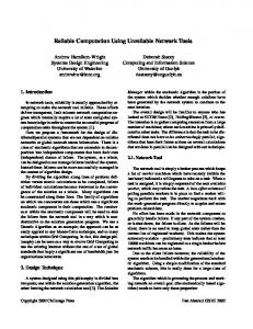
START
Algorithm
v,c, x 0 , ε
L ←x 0 , Lsol ←{}
L ≠ {}
N
Y
Pick up last box x from L Prune the box using HC4
Bisect x to x1 & x2 L ← L∪x ∪x 1
2
N
width ( x) ≤ ε Y
Lsol ← Lsol ∪ x
output Lsol
END
Theoretical Properties No need for approximation of FO system. Reliable in the face of computational errors. We do not miss out any spectral root in the given search domain. Accuracy guaranteed within user’s specification. The maximum error in the computed spectral point cannot be more than accuracy tolerance. Computationally efficient (HC4 filter)
Gas Turbine Engine A critical system in aircraft is the gas turbine engine. A gas turbine engine provides thrust under all conditions enveloping flight spectrum of altitude And speed. It is a is a complex machine consisting of a number of rotating and stationary components having aerodynamic and thermodynamic properties.
Schematic of Gas Turbine
Compressor Variable Geometry ( VG)
Hydromechanical
Nozzle
Fuel in
Main Burners
Reheat MainFuel
Systems
Nozzle actuators
Afterburner flow Distributor
VG
Gearbox Digital Electronic Control Unit
PLA
Manual Fuel Control Linkage
Various Gas Turbine Configurations A Single Spool Turbojet Power Plant consists of an intake, a compressor, a combustion chamber, a turbine and a propelling nozzle. A Twin Spool turbofan power plant consists of an intake, a low pressure compressor, high pressure compressor, a combustion chamber, a high pressure turbine, a low pressure turbine, a mixer, and a propelling nozzle.
Schematic of a Twin Spool Gas Turbine Engine
FLOW IN
LPC
Variable Geometry
HPC
Combustor
HPT
LPT
N O Z Z L E
FLOW OUT
Fuel Flow LPC: Low Pressure Compressor HPC: High Pressure Compressor LPT: Low Pressure Turbine HPT: High Pressure Turbine
23
Application to a Twin Spool Gas Turbine Plant Operating Regime : 90% to 93% high pressure spool speed demand. Input : Fuel rate to the gas turbine Output : High pressure spool speed Steady state values for i/p & o/p are 0.2442 Kg/sec & 20,620 rpm for 90% HP spool speed.
Identification at 90% HP spool speed Input : PRBS signal Sampling Time : 0.01 sec Method : Output-Error Identification Model Orders : OE221 to OE999 Identification- fractional and integer order models are obtained using output-error identification technique.
FO Model Identification FO model Structure used
b1 p ( s ) = α1 α2 a1s + a2 s + 1
OE identification technique with GL approximation and N = 25.
Gas Turbine Plant Cont. (Input Perturbation, 90% HP spool speed )
Gas Turbine Plant Cont. (Output, 90% HP spool speed)
FO Model Identified (90% HP spool speed) FO Model Identified is 103.9705 p( s) = 0.00734s1.6807 + 0.1356 s 0.8421 + 1
Model Validation (Input, 90% HP spool speed)
Model Validation (90% HP spool speed)
Respective MSEs for FO & IO are 2.34e-04 & 2.57e-03
FO Model Identified (93% HP spool speed) Similarly at another operating regime of 93% HP spool speed, the FO Model identified is 110.9238 p( s) = 0.0130 s1.6062 + 0.1818s 0.7089 + 1
Combined FO Model for 90-93% HP spool speed Combined model for 90-93% HP spool speed obtained by identification is b1 p( s) = , α1 α2 a1s + a2 s + 1 b1 ∈ [103.9705,110.9238], a1 ∈ [0.00734,0.0130], a2 ∈ [0.1356,0.1818], α1 ∈ [1.6062,1.6807],
α 2 ∈ [0.7089,0.8421],
Computation of spectral Set for combined FO Model of GT Denominator pseudo polynomial for the combined model of GT for 90-93% HP spool speed is
The uncertain parameter vector ‘q’ consists of a1 ∈ [0.00734,0.0130], a2 ∈ [0.1356,0.1818],
α1 ∈ [1.6062,1.6807], α 2 ∈ [0.7089,0.8421] ε = 0.025 r0 = [0,20], θ0 = [-π ,+π ] x0 = (r0 × θ0 × q0 )
Search domain and accuracy Initial search domain r0 = [0,20], θ0 = [-π ,+π ] x0 = (r0 × θ0 × q0 )
Spectral set is computed to an accuracy of ε = 0.025
Computed Spectral Set of combined FO Model of Gas Turbine
Analysis of Spectral Set for the combined FO model of the Gas Turbine Time taken for computation = 85 seconds No. of boxes generated = 539,497. Structural roots are found to be stable (All roots lie in the Riemann main sheet and their real parts are negative) From spectral set plot, the minimum damping factor is obtained as
Example-2 Non linear parametric uncertainty
Specifications ε = 0.1 r0 = [0,20], θ0 = [-π ,+π ] x0 = (r0 × θ0 × q0 )
Spectral Set (Ex-2)
Ex-2 Contd. Time taken for computation = 10 seconds No. of boxes generated = 30,743. Structural roots are found to be stable. From spectral set plot, the minimum damping factor is obtained as
Conclusions
Algorithms for computation of spectral sets for linear uncertain FOS. Problem is formulated as ICSP and HC4 filter is used for pruning the search domain. Demonstrated on practical application of a Gas Turbine plant.