J. Sütő et al. / Carpathian Journal of Electronic and Computer Engineering 5 (2012) 117-120 117 _____________________________________________________________________________________________________
Remote controlled data collector robot József Sütő*, S. Oniga**
*University of Debrecen/Faculty of Informatics, Debrecen, Hungary,
[email protected] **University of Debrecen/Faculty of Informatics, Debrecen, Hungary,
[email protected] Abstract - Today a general need for robots assisting different human activities rises. The goal of the present project is to develop a prototyping robot, which provides facilities for attaching and fitting different kinds of sensors and actuators. This robot provides an easy way to turn a general purpose robot into a special function one.
Key words: FPGA, Microcontroller, Android, Robot
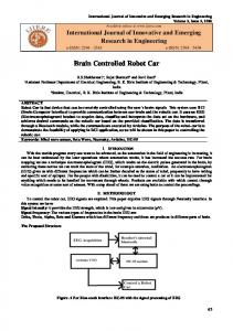
Fig. 1. Scheme of the project
I. INTRODUCTION Today a general need for robots assisting different human activities rises. The goal of the present project is to develop a general purpose framework, which provides facilities for attaching and fitting different kinds of sensors and actuators. This general purpose framework provides an easy way to turn a general purpose robot into a special function one. The final concrete goal of the present development is to develop an autonomous robot assisting clinical patients and/or elderly persons. The attached sensors collect information from the surrounding world and send it to a FPGA board. The FPGA board will controls the sensors and processes the measured values. Using the measured data the FPGA board can controls the robot’s movement. The implementation platform chosen is Nexys Spartan-6 FPGA Board. The sensors (light, humidity, temperature) attached to the board and the processed values appear on the graphic display. Finally, the robots can communicate to each other with the PmodRF2-IEEE 802.15 RF Transceiver. Fig. 1 shows the scheme of the robot. ISSN 1844 – 9689
The project consists in two major components: robot and cell phone. Between the robot and the cell phone communication is achieved using Bluetooth modules. The software implementation was done using Verilog hardware description language and java (android SDK) programming language. The PmodOLED’s controller code is written in C programming language and it runs in the PIC18F45K20 microcontroller. The robot is equipped with a Nexys3 FPGA Board with XILINX SPARTAN 6 FPGA, which controls the attached peripheral devices. It has two analog sensors: a light “sensor” (photo-resistor) and a humidity sensor (SYH-2R). A PmodAD1 converts the analog signals into digital values and then the FPGA can process the measured values. A DS18S20 digital thermometer measures the temperature. It has a 0.5 C accuracy from 10 C to +85. The FPGA board collects the measured values and then evaluates those. Using an ISD1760 voice record and playback device the robot play back template voices according to the measured values. A PIC18F45K20 microcontroller communicates with the FPGA board and handles the PmodOLED display, which displays the evaluated humidity and light information. Moreover, it includes a BTM-222 Bluetooth module. It can communicates with a cell phone (on the phone there is an android operation system) and according to the received information from the cell phone, the FPGA will handles the movement of the motors.
Fig.2. The robot
J. Sütő et al. / Carpathian Journal of Electronic and Computer Engineering 5 (2012) 117-120 118 _____________________________________________________________________________________________________
II. DESIGN Users can handle the robot with their cell phone that acts like a remote control. Moreover, users can set reference values (limits) for evaluation. FPGA receives the collected information from the environment and compares those with the limits. If the measured data are within the prescribed limits, the ISD1760 device will play back a template voice, for example: “The temperature is appropriate”. However, if the measured data are out of the limits, the device will play back another template voice, for example: “The temperature is inappropriate.” On the interface of the android application there is a button, which instructs the robot to process the measured information and play back the appropriate template voice if the user pushes a button. Nowadays, android system is present on many cell phones and it gives a lot of opportunities to developers. We used a Samsung cell phone with android 2.2 system and we created an android application, which handles the robot’s movement using the accelerometer of cell phone. Another possibility offered by the application is handling of the robot movement by touch screen. In the currently program code there are four activity classes. The first activity class handles the TabLayout, another handles the Bluetooth device list and the remaining two handle the user interfaces. In addition, there are three threads, responsible for Bluetooth connection and communication. Fig. 3 indicates the control scheme.
Fig. 3. Scheme of control
III HARDWARE The robot includes a Bluetooth module in order to give the users the ability of reaching the robot in 100 m area by cell phone or computer. The applied Bluetooth module is the BTM-222. This device provides full ISSN 1844 – 9689
Bluetooth data rate over UART and USB. The FPGA communicates with the BTM-222 over UART. Bluetooth modules accept AT commands. AT commands set the Bluetooth properties. The main properties are the baud rate, data bit, parity bit and stop bit. The control program of robot uses the factory settings. The communication speed is 19200 bit/sec. The sender and receiver routines send and receive eight data bits without parity bit and with one stop bit. If signal is detected, a service routine will be executed. The service routine processes the received data, commands the robot movement and sends back information to the user. Using an appropriate android program, which is able to handle the Bluetooth module of the cell phone, users can modifies the actuator’s direction and the speed of motors by their private cell phone. Fig. 4 shows the diagram of Bluetooth module.
Fig. 4. Block diagram of BTM-222
The used ISD1760 IC is a multi message chip which can record and play messages. The FPGA communicates with the IC via SPI. It can work in standalone or SPI mode. Sampling frequency of the IC is controlled by an external oscillator resistor. For a general application an 80 kΩ resistor is used, thus the sampling frequency is 8 kHz. Messages are contained in a circular memory. The FPGA accesses the circular memory, so it can play back messages from any memory location. By taking advantage of this availability, the robot can provide warning and indicator messages. In the currently conception of the robot it evaluates the temperature value and if there is within the limits ISD will plays back a template voice otherwise another template voice. Fig. 5 shows the SPI connection of ISD1700 series devices. In SPI mode control of the device is achieved through the 4-wire serial interface. The SPI mode allows full control of the device and the ability to perform complex message management. In order to perform functions normally correct numbers of data bytes are required to shift into the MOSI pin. Depending on the command
J. Sütő et al. / Carpathian Journal of Electronic and Computer Engineering 5 (2012) 117-120 119 _____________________________________________________________________________________________________
type, the format may be from two bytes to seven bytes long. The first byte sent to the device is always the command opcode byte, which determines the operation to be performed. MISO returns the status generated by the last command and current row address. Some commands provide additional information in the subsequent bytes. In SPI mode the user has the option to direct addressing with the SET_PLAY, SET_REC, SET_ERASE commands, which are capable of going around this structure. This is an advantage, if user wishes to implement a fragmented memory management scheme onto one of ISD1700 series device.
Fig. 5. Connecting the SPI interface
The robot includes a PIC microcontroller, which control the PmodOLED display. The microcontroller receives the data (16 bytes) from the FPGA board using UART protocol and then transmits the received bytes to the OLED display. A C program code controls the microcontroller. It contains header files to PmodOLED and other devices. In order to use the OLED display convenient, we had to modify the linker file. A main feature of the PIC microcontroller is the sequential instruction execution. Unlike the FPGA, in some cases the microcontroller provides an easier and more convenient way to solve tasks. PmodOLED requires lots of delay and the use of microcontroller is a better decision. The measured light and humidity values appear on a PmodOLED display. It is a 128x32 pixels graphic display and it has standard SPI interface, internal display buffer and 10 MHz clock speed. The graphic display panel uses the Solomon System SSD1306 display controller. SSD1306 embeds with contrast control, display RAM and oscillator. Data or commands are sent from parallel interface, in this case through SPI interface. It has GDDRAM a bit mapped static RAM, which holds the bit pattern to be displayed. The RAM is divided into pages, which are used for monochrome dot matrix display. ISSN 1844 – 9689
On the robot there is a PmodAD1 analog to digital converter, which converts the analog signals into digital values. It has some important properties: • • • •
One million samples per second Two 2-pole Sallen-Key anti-alias filter Two simultaneous AD conversion channels Converts into a 12-bit digital value
The device uses the SPI/MICROWIRE serial bus standard to send converted data to the host system. PmodAD1 include two AD7476A AD converter chips. The reference of AD7476A is derived from the power supply and it requires low power consumption. The used PmodAD1 receives the analog signals from the photo-resistor and the humidity sensor. In the program code a method gets the digital values and gives back the relative humidity value. A DS18S20 digital thermometer measures the temperature. This IC applies an one wire communication protocol and can measure the temperature with 0.5 C accuracy. The device can be powered from data line in parasite power mode. The supply range is 3V to 5.5V. It measures temperature from -55 C to +125 C. The conversion time of the device is maximum 750ms. In our solution the DS18S20 is sampling the temperature in every second. The temperature data is stored as a 16 bit extended two’s complement number in the temperature register. DS18S20 has a complex read and write timing. Fig. 6 shows the DS18S20’s read and write timing.
Fig. 6. DS18S20 read and write timing
IV. CONCLUSION The movement of the remote controlled data collector robot is not smooth and the resulting trajectory is curve. A significant requirement of the prototype robot was the low cost and the cause of the irregular motor
J. Sütő et al. / Carpathian Journal of Electronic and Computer Engineering 5 (2012) 117-120 120 _____________________________________________________________________________________________________
movement problem is the low quality of the motors. The BTM222 has an excellent range without antenna and it can communicate with the smart phone inside a huge area. Aside from shown little disadvantages the robot is working correctly. Moreover, the developed hardware elements and the implemented methods are used in other developments as well. In the future some additional devices will be attached to the framework, for instance: a WIFI module.
ACKNOWLEDGMENT THE PUBLICATION WAS SUPPORTED BY THE TÁMOP4.2.2.C-11/1/KONV-2012-0001 PROJECT. THE PROJECT HAS BEEN SUPPORTED BY THE EUROPEAN UNION, COFINANCED BY THE EUROPEAN SOCIAL FUND.
ISSN 1844 – 9689
REFERENCES [1] Digilent Inc., Nexyx3 Board Reference Manual. December 28, 2011. [2] Digilent Inc., Digilent PmodAD1 Analog To Digital Module Converter Board Reference Manual. December 6, 2011. [3] Digilent Inc., PmodOLED Reference Manual. October 9, 2011. [4] Digilent Inc., PmodRF2 Reference Manual. May 09, 2011. [5] Microchip Technology Inc., PIC18F23K20/24K20/25K20/26K20/43K20/44K20/45K20/46K20 Data Sheet. 2009 [6] Samyoung S&C Co., SYH-2R Series Specifications. 2011 [7] Texas Instruments, L293D Quadruple Half-H Drivers. November 2004 [8] Rayson Technology Inc., BTM222 Bluetooth Module data sheet. 11/10/2005 [9] Winbond, ISD1700 Multi Message Single Chip Voice Record & Playback Devices. January 22, 2007 [10] Dallas Semiconductor, DS18S20 High Precision 1-Wire Digital Thermometer data sheet 043001 [11] Microchip Technology Inc., MPLAB C18 C Compiler User’s Guide. 2005. [12] Pong P. Chu. FPGA Prototyping By Verilog Examples. A JOHN WILEY & SONS, INC., PUBLICATION. 2008