Reorder Buffer: An Energy-Efficient Multithreading Architecture for Hardware MIMD Ray Traversal Won-Jong Lee∗ Youngsam Shin† Seok Joong Hwang‡ Seok Kang § Jeong-Joon Yoo¶ Soojung Ryu k SAMSUNG Advanced Institute of Technology
Abstract In this paper, we present an energy- and area-efficient multithreading architecture for Multiple Instruction, Multiple Data (MIMD) ray tracing hardware targeted at low-power devices. Recent ray tracing hardware has predominantly adopted an MIMD approach for efficient parallel traversal of incoherent rays, and supports a multithreading scheme to hide latency and to resolve memory divergence. However, the conventional multithreading scheme has problems such as increased memory cost for thread storage and consumption of additional energy for bypassing threads to the pipeline. Consequently, we propose a new multithreading architecture called Reorder Buffer. Reorder Buffer solves these problems by constituting a dynamic reordering of the rays in the input buffer according to the results of cache accesses. Unlike conventional schemes, Reorder Buffer is cost-effective and energy-efficient because it does not need additional thread memory nor does it consume more energy because it makes use of existing resources. Simulation results show that our architecture is a potentially versatile solution for future ray tracing hardware in low-energy devices because it provides as much as 11.7% better cache utilization and is up to 4.7 times more energy-efficient than the conventional architecture. CR Categories: I.3.1 [Computer Graphics]: Hardware Architecture—Graphics processors; I.3.7 [Computer Graphics]: Three-Dimensional Graphics and Realism—Raytracing; Keywords: ray tracing, GPU, mobile, multithreading
1
Introduction
The continuous growth of the mobile market segment in recent times has resulted in ray tracing being highlighted as a new rendering algorithm to produce high-quality images for mobile graphics applications such as UX/UI, Game, and AR/VR. However, realtime ray tracing in current mobile GPUs is not possible because of limited computing performance, memory bandwidth, and power constraints. Thus, various hardware-based ray tracing solutions such as fully dedicated hardware [Nah et al. 2014b], hardwaresoftware hybrids [Lee et al. 2013], and GPU IPs [McCombe 2014] are being proposed to solve these problems in mobile devices. One key feature of recent ray tracing system is its capability to take advantage of the MIMD ray traversal approach [Kopta et al. 2010; ∗ e-mail:
[email protected] † e-mail:
[email protected] ‡ e-mail:
[email protected] § e-mail:
[email protected] ¶ e-mail:
[email protected] k e-mail:
[email protected]
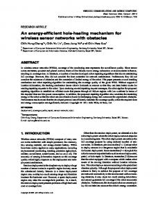
Nah et al. 2011; Kim et al. 2012a; Lee et al. 2013; Nah et al. 2014b; Nah et al. 2014a; Keely 2014]. Because the MIMD approach can enable efficient parallel processing of incoherent rays by resolving branch divergence, it was extensively utilized in shared and distributed memory machines in past research [Cleary et al. 1986; Gaudet et al. 1988; Kobayashi et al. 1988; Priol and Bouatouch 1989], and has seen renewed interest owing to its possible utilization in mobile ray tracing hardware. However, MIMD traversal cannot resolve the memory divergence problem that still remains a critical issue, even though it can handle branch divergence. Recent architectures have tackled the memory divergence problem in two ways. In the first approach, ray scheduling is used to control memory access patterns in order to improve the cache locality [Kopta et al. 2013; Keely 2014]. This approach decomposes a tree into small sub-trees, called treelets [Aila and Karras 2010], which fit into the local cache, and reschedules the processing order of rays, which eventually contributes to performance improvement. In the second approach, hardware multithreading is used to efficiently hide the memory latency caused by cache misses [Nah et al. 2011; Lee et al. 2013; Kwon et al. 2013; Nah et al. 2014b; Nah et al. 2014a]. By immediately processing the subsequent rays whenever a ray encounters a cache miss, pipeline stalls are avoided and hardware utilization is increased. The multithreading approaches used in ray tracing hardware are advantageous in terms of cost, because they use fewer register files than conventional GPU multithreading. However, the multithreading architecture used in conventional ray tracing hardware has problems that results in extra memory being required to store the ray threads that miss the cache [Nah et al. 2011; Lee et al. 2013; Nah et al. 2014a], or additional energy/power being consumed to bypass ray threads that miss the cache to the pipeline [Nah et al. 2014b]. Figure 1 shows the profile results of the energy consumption (without that of the DRAM) for rendering on our baseline ray tracing hardware (Section 4). The figure shows that the traversal and intersection logic modules are responsible for 83% of overall consumption. This trend can become worse as a result of the pipeline bypassing, which increases the number of circuit switches and memory accesses. Thus, we propose a new energy- and area-efficient multithreading architecture for MIMD ray tracing hardware. The key idea underlying our solution is dynamic reordering of the processing rays stored in the input buffer according to the result of cache access, which is inspired by the out-of-order non-blocking cache [Farkas and Jouppi 1994]. If the ray fetched from the input buffer encounters a cache miss, the input buffer holds the corresponding thread and subsequent ray threads are scheduled to be processed. The rays that missed the cache in the buffer are retained only during the time of miss penalty, which minimizes unnecessary re-accesses to the cache. Moreover, our scheduler logic in the buffer improves ray coherency by ensuring that rays with the same address are processed contiguously, which can also reduce the off-chip traffic and the energy consumed. Unlike the conventional architecture, our architecture is cost-effective because it does not incur extra memory cost for storing threads, and is also energy-efficient because it does not bypass the rays that miss the cache. The concept of this architecture was previously proposed in an extended abstract [Lee et al. 2014b]. We verified the validity of the proposed multithreading architec-
Energy consumption ratio (%)
80
60
in the professional graphics arena, rather than real-time applications such as the PC/video games field because they are still not fast enough yet.
58.16
40 27.19 20
7.59
6.26
0.81
0 Traversal
Intersection
L1 cache
L2 cache
Etc.
Figure 1: Decomposition of power consumption results for one frame rendering on our baseline T&I unit RTL architecture (with the exception of DRAM). The numbers were obtained via gate-level simulation and evaluation with Synopsys PrimTime PX [Synopsis 2015].
ture via the cycle-accurate simulation integrated energy model. The model provided various simulation results on cache and pipeline utilization and performance and energy efficiency after running the diffused path tracing of four test scenes. The simulation results show that our architecture achieves up to 11.7% better cache utilization and up to 4.7 times the energy-efficiency of the conventional architecture1 . These results reflect the minimal usage of memory resources and efficient usage of hardware that characterize our proposed architecture. Thus, our architecture is a potentially versatile solution for future ray tracing application, particularly latencycritical applications such as Virtual Reality [SAMSUNG 2015] in the mobile SoC environment [Exynos 2015]—which is subject to memory latency, energy, and area constraints.
2
Background
The traditional ray tracing algorithm in the PC environment has evolved to using parallelization supported by target platforms. High performance SIMD architectures have been developed for desktop CPUs/GPUs to support massive data parallelism, and ray tracing algorithms have aggressively utilized this SIMD feature. Packet tracing [Wald et al. 2001; Overbeck et al. 2008; Garanzha and Loop 2010], in which multiple rays intersect in a single box, and multibranching BVH [Ernst and Greiner 2008; Wald et al. 2008; Tsakok 2009], in which multiple boxes can be tested with a single ray, are all algorithms developed to efficiently utilize the SIMD architecture. In the past, when the computing power of CPUs/GPUs was insufficient to support real-time rendering, researchers naturally considered dedicated hardware solutions [Schmittler et al. 2004; Woop et al. 2005]. These specialized hardware were designed as SIMD architectures and realized real-time ray tracing at a low-cost by combining the features from GPU (such as SIMD multithreading and latency hiding) and the benefits of the dedicated hardware (such as traversal and intersection pipeline, and multi-level cache systems). However, rapid advances in desktop GPUs and an increasing number of cores and SIMD lanes in CPUs and computing coprocessors such as Many Integrated Core (MIC) resulted in software-based real-time ray tracing a reality. Software ray tracing solutions that adopted this technology were released into the market and made a huge contribution to high-quality rendering [Parker et al. 2010; Wald et al. 2014]. However, these solutions are mainly being used 1 In this paper, the “conventional architecture” means the architecture using previous multithreading methods, the RAU and the Retry. In contrast, the “baseline architecture” means the single-thread architecture not employing any multithreading method (without non-blocking cache).
In contrast, the explosive growth of the mobile market has continued unabated and various realistic and immersive graphics applications, including UI/UX, Game, and VR/AR are being developed for the various mobile gadgets such as smartphones, tablet/phablet, and wearable devices. With the growth of the market and the increasing demands for photorealistic graphics, real-time ray tracing in the mobile domain has become an attractive option. Ray tracing, in particular, is being considered a potential rendering algorithm that will facilitate a new immersive experience for Head Mount Display (HMD)-based VR applications that enable users see the rendering through the lens in the near-eye field, because it can provide physical light effects such as reflection, refraction, and shadow without distortion [Fujita and Harada 2014; Harada 2014]. However, mobile computing is currently still not able to realize real-time ray tracing. The practical computing power of recent mobile GPUs released in the market have not scaled linearly as had been expected. The theoretical peak performance (for the computing power of 32 bit floating point) of the current mobile flagship GPUs in smartphones is in the range 200∼300 GFLOPS [ARM 2015; Qualcomm 2015], and is estimated to attain a mere 400∼500 GFLOPS even when the future mobile GPUs to be released in the next one to two years are considered. Moreover, only one-half of the stated speed can be available in terms of practical performance because of power and heat limitations. In contrast, real-time ray tracing of real-world applications such as games requires computing power in the range 5∼6 TFLOPS (WQHD, 30 fps). This means that a performance gap of over 20 times the current speed exists. Consequently, interest in dedicated hardware [Lee et al. 2013; McCombe 2014; Nah et al. 2014b] for the mobile domain has naturally been renewed with a view to satisfying market demands for highquality graphics using high performance and low-power solutions. The key feature of the recently proposed ray tracing hardware is its design on an MIMD architecture, instead of SIMD, which is widely utilized in traditional CPU/GPU based ray tracers. This feature can be shown in not only mobile targeted [Kim et al. 2012a; Lee et al. 2013; Nah et al. 2014b] but also PC targeted hardware [Nah et al. 2011; Nah et al. 2014a; Keely 2014], because the MIMD architecture is more advantageous for branch-intensive incoherent ray tracing by independent parallel processing of ray threads. Conversely, software ray tracers have been developed with the parallelization method, i.e., SIMD, and supported by existing platforms. The ray tracing architecture has also evolved to be more advantageous as designers design new hardware platforms. However, even though MIMD architecture improves on parallelism by resolving the branch divergence, the performance degradation by memory divergence still remains an unresolved problem in the MIMD architecture. On the other hand, the latency hiding has been a major concern in computer architecture fields, which has driven a variety of the non-blocking cache architectures. Standard non-blocking caches employ an array of miss status holding registers (MSHRs) to track the mapping between identification tags received from the client and outstanding requests sent to the next level cache. According to the ways to organize the MSHR, a several architectures have been proposed˙Implicitly addressed MSHRs [Kroft 1981] is allocated per primary miss and is recorded at most one identification tag for each individual word in the cache line. Explicitly addressed MSHRs [Farkas and Jouppi 1994] is allocated per primary miss and is recorded a total identification tags regardless of which word they reference. Inverted MSHRs [Farkas and Jouppi 1994] is allocated statically for each possible identification tag and are enumerating
rays
rays
rays
Input Buffer 0x8 0x4 0x1
Ray Accumulation Unit
R13 R11 R10
miss
Buffer
Control
0x8 0x4 0x1
Non-Blocking
data
CACHE
rays R0
R3
R7
R9 0x1
4
N
R2
…
...
0x2
3
N
0x3
1
N
0x4
2
N
.. …
…
R13 R11 R10
Non-Blocking
data
CACHE
hit
hit
or
miss
Pipeline latch
counter ready addr. data
rays
Input Buffer
Pipeline latch
miss
Logic
Logic
hit
TRV Pipeline
TRV Pipeline
Pipeline
Pipeline
(Traversal or Intersection)
(Traversal or Intersection)
(a) Ray Accumulation Unit
(b) Retry
Figure 2: Two conventional multithreading architectures for MIMD ray tracing hardware. (a) Ray Accumulation Unit (RAU): the ray thread that miss the cache is stored in the dedicated memory buffer, called the Ray Accumulation Buffer (RAB), and is scheduled for latency hiding. If the ray (R10) is cache-missed and an RAB row with the same address (0x1) is already full, RAB cannot be used and the pipeline has to be stalled even though the other row has an empty slot. (b) Retry: even though the pipeline stall can be avoided because the ray thread that missed the cache is invalidated and fed to the pipeline, thread bypassing can cause additional energy consumption by logic switching or data movement in-between pipeline registers.
using a n-way comparator when the data arrives from the next level cache. The traditional approach to alleviating the performance degradation by memory divergence is to aggressively use latency hiding as well as improve the cache locality. To achieve this, recent MIMD ray tracing hardware have increased hardware utilization with unique latency hiding methods that are all able to conduct subsequent ray processing without pipeline stalls via zero-overhead thread switching whenever cache misses occur. In next section, we describe the hardware multithreading scheme for MIMD ray traversal which is main topic of this paper.
3
H/W Multithreading for MIMD Ray Tracing
The multithreading architecture for recent MIMD ray tracing hardware was designed in order to overcome the limitations of GPU ray tracers. Modern GPU architectures support hardware multithreading to achieve massive parallelism. In this approach, several hundred to thousand threads are concurrently executed, and even if some threads stall, others can execute during the next cycles. However, incoherent ray traversal with this SIMD-friendly multithreading architecture can increase random memory access and make cache utilization worse. The register area per streaming multiprocessor (SM) in NVIDIA GPUs is much greater than the compute area per SM [Kopta et al. 2010]. To minimize this inefficiency in terms of area and cache utilization for hardware multithreading, two architectures, called Ray Accumulation Unit (RAU) and Retry, were proposed. In this section, briefly we describe this multithreading architecture.
3.1
Ray Accumulation Unit
Nah et al. [2011] proposed a unique multithreading architecture, called RAU (Figure 2(a)), in their desktop-level ray tracing hardware accelerator called the T&I Engine. The RAU consists of a dedicated memory buffer, called the Ray Accumulation Buffer (RAB), and control logic. The RAB consists of several fields for storing thread information, ray data, cache address, occupation counter,
and ready bit, and is structured using two-dimensional representation to group rays that have the same address. The cache is designed as a non-blocking type to service subsequent requests even after a cache miss has occurred. The operational flow of the RAU is as follows. Initially, the pipeline accesses the cache for a ray thread. If a cache miss occurs, the RAU allocates space and stores the corresponding ray thread. If the cache address of the rays fetched from the input buffer is the same as the address among the rays stored in the RAU, the corresponding ray is stored in the same row in an RAB, which improves the cache locality by subsequently fetching these rays when the requested data arrive at the cache. Subsequently, the pipeline first searches the row of “ready rays” in the RAB, that is, the rays for which the miss is complete and the requested data have arrived at the cache. If this has occurred, the rays in the corresponding row are fetched in a cycle-by-cycle manner; otherwise, the next ray waiting in the input buffer is fetched. The RAU borrowed the concept of the explicitly addressed MSHRs [Farkas and Jouppi 1994], each row of the RAB corresponds to one outstanding cache line address and collects up to N rays (requests). The RAU can efficiently hide the latency by accumulating the ray thread that missed the cache in the dedicated buffer, and immediately process the other rays. Moreover, the rays that reference the same cache line are accumulated in the same row in an RAB, which can achieve ray reordering effects. However, there are two disadvantages to using the RAU. First, it requires additional buffer memory for the RAB (3 KB per pipeline, 60 KB in the case of the T&I unit [Lee et al. 2013] (i.e., 3 KB per pipeline × 20 pipelines (5 pipelines–comprising four traversals and one intersection–per core × 4 cores))). Second, the RAB can overflow in the early stage when it is adapting to environments that require relatively long DRAM latencies (100∼300 cycles), such as mobile SoC. In particular, there can be an inappropriate case, such as if the ray (R10) is cachemissed and an RAB row with the same address (0x1) is already full–in which case the RAB cannot be used and the pipeline has to be stalled even though the other row has an empty slot (Figure 2(a)). Thus, the pipeline stall resulting from this early RAB overflow cannot be avoided.
3.2
The Retry Method
As an alternative solution, Kwon et al. [2013] proposed a new multithreading method, called Retry, that efficiently hides the latency in texture fetches for Coarse Grained Reconfigurable Arrays (CGRA) based mobile GPUs that schedule the kernels in compile time. The Retry architecture does not store the threads when access to the texture cache is missed. Instead, it invalidates the cache-missed threads and executes the kernels with valid and invalid threads in order to avoid pipeline stall. If the texture cache miss is complete, kernel execution is retried for the invalid threads. A mobile GPU is also based on this retry approach [ARM 2015]. The recent ray tracing hardware RayCore [2014b] uses the same idea for latency hiding, called in this case “looping for next chance,” which invalidates the ray threads that missed the cache and feeds them to the pipeline. The invalidated ray threads are bypassed in the pipeline stages and re-entered into the input buffer through a feedback loop, and then cache access is retried (Figure 2(b)). This architecture is easily implementable with a single-threaded pipeline and nonblocking cache and the state machine for control logic is quite simple. In particular, it does not require any additional memory because the pipeline register can be reused for thread storage. However, this architecture has a critical disadvantage in that it can increase the amount of energy consumed because pipeline bypassing of the invalidated threads causes increased circuit switching and access to internal memory elements. In particular, if the DRAM latency increases, the number of bypasses can also increase because the miss penalty is not complete, even though the invalid ray threads have re-entered the pipeline through the feedback loop. For example, if a ray tracing pipeline with 20 stages (T&I units in RayCore [2014b]) is adopted to mobile SoC, in which the DRAM latency usually requires 100∼300 cycles, the ray threads that meet the miss in the level-one (L1) and level-two (L2) cache have to bypass the pipeline at least 5∼15 times meaninglessly. Moreover, whenever an L1 cache miss occurs, it is simply fed to the pipeline for the next chance; thus, the corresponding thread is bypassed even when the L2 cache is a hit. This can increase the number of pipeline bypasses and access to the cache, which increases the amount of energy consumed. As a result, this feature of the Retry architecture can be a crucial disadvantage in systems targeted at mobile devices. We propose a new multithreading architecture for MIMD ray tracing hardware that solves the problems experienced by the RAU and Retry architectures, and provides latency hiding without additional energy and memory consumption.
4
Proposed Architecture
The goal of our research is to develop a low-cost and low-energy hardware multithread architecture for MIMD ray traversal that can be adopted for use by dedicated hardware [Nah et al. 2014b], hardware-software hybrid solutions [Lee et al. 2013], and ray traversal hardware integrated into existing GPUs [McCombe 2014; Keely 2014]. We begin with a baseline architecture, called the T&I unit [Lee et al. 2013] (Figure 3), which is an accelerator hardware for traversal and intersection operation that is used in a ray tracing GPU, called Samsung reconfigurable GPUs based on Ray Tracing (SGRT), targeted at mobile SoC. The T&I units have been implemented at the level of RTL with verification at the FPGA and ASIC levels [Lee et al. 2014a], and also have a flexible cycleaccurate simulation model to enable easy and fast architecture exploration [Kim et al. 2012b; Lee et al. 2014b; Lee et al. 2014a]. The baseline MIMD architecture model, i.e., T&I units, consists of a ray dispatch unit (RD), multiple traversal units (TRVs), and an intersection unit (IST). Each unit is connected to an internal buffer
From Shader (Rays)
Ray Dispatch Unit
TRV Units Input Buffer
Pipe
L1$
Input Buffer
Pipe
Stack
Input Buffer
L1$
Pipe
Stack
To Shader (Hit points) IST Unit
L1$ Stack
Input Buffer
Pipe
L1$
L2 Cache
Stack
Input Buffer
Pipe
L1$
Figure 3: Our baseline hardware architecture, T&I units.
that passes rays between units. The RD fetches rays from the ray buffer if it is used in the shader core of GPUs [Lee et al. 2013; McCombe 2014; Keely 2014] or dedicated hardware [Nah et al. 2014b], and dispatches them to idle TRVs. MIMD ray traversal is performed by the TRVs, each of which consists of a memory processing module (input buffer, L1 cache, stack) and a computation pipeline. The L2 cache for multiple TRVs between off-chip memory and the L1 cache reduces memory traffic and facilitate scalable performance. The computation pipeline includes the general operation for BVH traversal such as node test, ray-nodeAABB intersection test, and stack operation. The output of the TRV pipeline branches into three paths: a feedback loop path to the input buffer for iterative visits to the inner nodes; an output path to send rays to the IST when they reach a leaf node; and an output path to send rays to the shader when they have completed BVH tree traversal. The IST unit is identical to the TRV unit except for the operation in the pipeline and the existence of the stack. The goal of our multithreading architecture is to efficiently disguise long memory latency at low-cost and low-energy consumption. To prevent unnecessary energy consumption without incurring additional memory cost, we reuse the existing resources, such as the input buffer, of the baseline architecture. If the ray fetched from the input buffer misses the cache, it is simply retained in its place in the input buffer. In other words, the storing and buffering of the ray threads that miss the cache are accomplished in the same space. By adding a small field (28 bits per entry) to the input buffer, we satisfy these requirements. This new input buffer is called the Reorder Buffer, because the processing order of the ray is dynamically reordered in this buffer. The Reorder Buffer is cost-effective because it does not need dedicated memory for storing threads, and is also energy-efficient because it does not bypass the invalidated rays. Moreover, the priority-based scheduler of the Reorder Buffer can improve the cache locality and minimize re-access to the cache. Modern GPUs based on the sort-last fragment approach also use a reorder buffers which exists between shader and raster operation (ROP) units, as described by Ragan-Kelley et al [2011]. Strict ordering is enforced using reorder buffers of hundreds or thousands of entries before the ROP units that update the framebuffer. This allows fragments to be kept asynchronous and independent to as late as possible in the pipeline, maximizing available parallelism at the cost of fine-grained global synchronization. Unlike the reorder buffer in GPUs, the purpose of our reordering is not to keep strict ordering but to energy-efficiently hide latency.
rays
valid ready addr.
rays
Found a ray on cache event?
ray
.
…
…
…
1 0 0
0 0
0x8 0x4 0x1
R13 R2 R0
Reorder Buffer Buffer
Control
data
CACHE
Found a new ray?
(ready ==‘1’)
Yes No
Non-Blocking
hit
(valid==‘1’)
Cache request:
Wait
the shape address of the ray Pipeline latch
First stage
Logic
Second stage Cache hit?
TRV Pipeline
Output the ray to the pipeline Pipeline
Retain the ray (ready ‘0’, valid ‘0’)
(a) Output scheduling
(Traversal or Intersection)
Is the buffer full?
Figure 4: Reorder Buffer–the proposed architecture
4.1
Input a new ray (Rn) to the buffer
Reorder Buffer
Figure 4 shows a hardware unit in the ray tracing hardware of the proposed multithreading architecture, Reorder Buffer. Similar to the RAU and the Retry, the cache is designed as non-blocking in order to service subsequent requests even after a cache miss has occurred. The cache system passes several signals to the control logic in the Reorder Buffer. These signals include not only the results of L1 cache access (hit/miss) but also other cache events such as the results of L2 cache access (hit/miss) and notification of miss completion. The Reorder Buffer is inspired by the inverted MSHRs [Farkas and Jouppi 1994] that handle the outstanding miss requests in standard non-blocking cache architectures.
Found a ray (Rs) has the same addr. as Rn?
• Address (26 bits): The cache address is used to reference the data. The Reorder Buffer has a cache address for two reasons.
(valid ‘1’, ready null)
Wait
(b) Input scheduling
Figure 5: Operational flow of the Reorder Buffer (a) output (b) input.
First, when the cache miss is complete and the requested data arrive at the cache block, the cache searches for the ray that requested the corresponding data in the Reorder Buffer with this address as a key. Second, when a new ray arrives at the Reorder Buffer, the control logic tests whether there is a retained ray that has the same address as that of the new ray (Section 4.2). The address field does not need to store the cache line offset (6 bits) because it can guarantee the uniqueness as a key with the tag and the set part. The cached data can be a BVH tree node [Lee et al. 2013] or a primitive AABB [Nah et al. 2014a] if the pipeline is the TRV unit, and a primitive if the pipeline is the IST unit.
To schedule the rays in the Reorder Buffer, we add the following information (28 bits per entry) to the input buffer:
• Ready (1 bit): This is a Boolean value that indicates whether a retained ray is ready to enter the pipeline when the cache miss is complete. If a ray has missed cache access, it is retained and its Ready bit is set to “0.” When the requested data arrive at the cache from lower level memory and the corresponding cache line is filled with the arrived data, the cache searches the retained rays that have the same address and sets their Ready bits to “1.” In the next cycle, the pipeline fetches the rays that have their Ready bits set to “1” and enters them with the cache data into the pipeline.
Initialize Rn
Update Rn from Rs
(valid ‘0’, ready ‘0’)
The Reorder Buffer, a key component in our multithreading architecture, consists of buffer memory and simple control logic. The buffer memory holds and retains the threads, and the control logic manages ray scheduling. The pipeline is the computation logic that performs traversal or intersection operations. The TRV and the IST units can be designed either as separate units [Schmittler et al. 2004; Woop et al. 2005; Lee et al. 2013] or as one integrated unit [Nah et al. 2014b]. The Reorder Buffer can be applied to both types. As can be seen in Figure 4, the dedicated memory and the bypass path are eliminated, as per our goal.
• Valid (1 bit): This is a Boolean value that indicates the type of ray stored in the buffer. If the ray has newly arrived in the buffer and has not yet accessed the cache, the control logic sets this value to “1.” If the ray has accessed and missed the cache, the value is set to “0.” This value is used for ray scheduling (Section 4.2) with the Ready bit.
Yes No
The overhead that is added to the Reorder Buffer is minimal. As stated previously, only 28 Bits (address, ready, and valid bits) are needed per entry. If the size of the Reorder Buffer is 32, the required additional memory is 112 Bytes (32 × 28 bits). This additional overhead is negligible compared with the baseline and Retry architectures. In contrast, the additional memory size for RAU, i.e., RAB, from the baseline architecture is 2,976 B (32 × ray payload + 8 × (cache address, cache data, occupation counter, ready bit) = 32 × 84 B + 8 × 36 B) if the combination is a 4 × 8 array, which is the optimal size in terms of performance per unit size [Nah et al. 2011]. Thus, the Reorder Buffer can conserve up to 26.6 times more memory than with the RAU.
4.2
Ray Scheduling
In this section, we describe the principle of ray scheduling and the operation of the Reorder Buffer. In the Reorder Buffer, if any ray fetched from the buffer has missed the cache, the corresponding ray
. . (R3, 0x4) (R2, 0x3) (R1, 0x2)
valid ready addr
. . (R3, 0x4) (R2, 0x3) ray
valid ready addr
. . (R3, 0x4) ray
Cache -
0x1
ray
request
request
1
valid ready addr
. .
R0
1 0
0
0x2 0x1
R1 R0
R0 Miss
valid ready addr request
Cache
1 0 0
0 0
0x3 0x2 0x1
R2 R1 R0
R1 Miss
Cache
R1 Retained
R0 Retained
ray
1
-
0x4
R3
0 0
0 0
0x2 0x1
R1 R0
R2 Hit!
Cache
R2 dispatched R2 + cache data
(a)
(b)
(d)
(c)
(R11, 0x5) valid ready addr
1 0 0 0
0 0 1
0xA 0x5 0x2 0x1
valid ready addr
ray
R10 R4 R1 R0
Cache cache event (miss complete at 0x1)
1 1 0 0 0
0 0 1
ray
0x5 0xA 0x5 0x2 0x1
R0 Selected
R11 R10 R4 R1 R0
valid ready addr cache event (miss complete at 0x2)
Cache
request
. . .
. . .
(e)
(f)
1 1 0 0
0 0
ray
0x5 0xA 0x5 0x2
R11 R10 R4 R1
valid ready addr
updated
R0 Hit!
request
R0 dispatched
R0 + cache data
. .
(g)
Cache
0 1 0
0 0
ray
0x5 0xA 0x5
R11 R10 R4
R1 Hit!
Cache
R1 dispatched R1 + cache data
R0 + cache data
. .
(h)
Figure 6: Operation of the Reorder Buffer: (a) Rays R1–R3 are entering the buffer, R0 arrives and accesses the cache with address 0x1. (b) In the next cycle, R0 misses access and is retained (valid/ready is set to “0”). At the same time, R1 arrives and accesses the cache with address 0x2. (c) In the next cycle, R1 misses access and is retained and R2 also accesses the cache. (d) In the next cycle, R2’s access is a hit in the cache and R2 is dispatched to the pipeline with cache data, while R0 and R1 are still retained. (e) After several hundred cycles, the retained and new inputted rays are mixed in the buffer. The cache event (miss complete) occurs and the “ready bit” of the rays with the address 0x1 is set to “1.” (f) R0 is selected with high priority (ready bit is “1”) by the pipeline and accesses cache again. (g) In the next cycle, R0’s access is a hit in the cache and it is dispatched to the pipeline. (h) New input ray R11 references the same address with retained ray R4 in (g); thus, R11’s valid/ready bit is set to “0.” Rays R4 and R11 are set to be processed subsequently after the miss is complete.
is retained and the next ray is processed in order to avoid a pipeline stall. Therefore, the retained rays and the newly inputted rays coexist in the buffer. The priority with which rays are selected from among them can affect the overall performance. Figure 5(a) is the operational flow of the output scheduling in the Reorder Buffer. The operation primarily comprises two stages. In the first stage, a ray is selected and a request is made to the cache. In the second stage, the ray is processed in accordance with the results of cache access. This is similar to the scheduling scheme of the RAU [2011], but the algorithm (and control logic) is much simpler. If there are rays to be processed in the Reorder Buffer, the pipeline selects a ray using the following priority scheme. 1. The “ready rays” with ready bit set to “1” by the cache events (L1 cache miss completion (cache line fill) or L2 cache hit) are selected first, because their requested data exist in the cache. 2. “New rays,” which have valid bit set to “1,” are selected. Once a ray is selected by the pipeline, the corresponding ray accesses the cache and, if a cache hit occurs, the ray is immediately dispatched with the cached data and removed from the buffer. Otherwise, the ray is retained in the buffer and its valid/ready bit is set to “0.” If a cache miss has occurred, the request is transferred to the next-level memory and the non-blocking cache prepares to accept the next requests. Thus, the pipeline does not have to be stalled
during miss penalty. Figure 5(b) depicts the operational flow of input scheduling in the Reorder Buffer. When a new ray is inputted to the buffer, the buffer might already have rays that reference the same address as the new ray, which implies that the data referenced by the new ray were already requested by a certain ray in the buffer. Thus, the new ray does not have to access the cache, and just waits for arrival of the data. In this case, the valid/ready bit of the new ray is set to “0” without any cache access. Once the cache miss is complete and the cache signals to the Reorder Buffer, the cache searches the rays in the buffer that have the same address and set their ready bits to “1.” Two rays that have the same address become ready at once, and are subsequently fetched in the next cycle by the selection algorithm (Figure 5(a)). Thus, the Reorder Buffer can achieve the reordering effect to improve ray coherency, which is a feature of the RAU. In the RAU, there was a problem when a ray missed the cache and the RAB row that had the same address was already full; the RAB could not be used even though the other row may have had an empty slot. Unlike the RAU, the Reorder Buffer can maximize the reordering effect as long as there is space in the buffer and no overflow is likely to occur. Our scheduling algorithm has a similar purpose to that of the inverted MSHR [Farkas and Jouppi 1994] in the non-blocking cache. The MSHR is a hardware data structure that holds various pieces
Table 1: Comparison of the cache miss ratio with varying the DRAM latencies.
Test scene Conference (282K tri.)
Fairy (174K tri.)
Hairball (2.9M tri.)
San Miguel (7.8M tri.)
DRAM latency 10 100 200 300 10 100 200 300 10 100 200 300 10 100 200 300
L1 cache Multithreading method Baseline RAU Retry Reorder 10.45 10.03 9.68 9.22 11.94 10.18 9.71 9.12 12.21 10.51 9.83 9.15 13.71 11.29 10.38 9.55 15.24 14.64 13.80 13.53 17.55 14.90 13.83 13.49 17.58 15.13 13.84 13.45 17.62 15.27 13.84 13.43 34.99 33.41 27.66 27.42 42.35 35.54 28.76 28.47 66.05 42.84 32.21 31.69 48.63 43.73 32.51 32.01 58.95 35.88 28.59 28.17 64.55 36.64 28.94 28.51 66.68 37.07 29.15 28.73 67.93 37.48 29.21 28.80
Reduction from RAU Retry +0.82 +0.46 +1.06 +0.58 +1.35 +0.68 +1.74 +0.84 +1.10 +0.27 +1.40 +0.34 +1.68 +0.39 +1.84 +0.42 +5.99 +0.24 +7.07 +0.29 +11.15 +0.52 +11.72 +0.51 +7.72 +0.42 +8.13 +0.43 +8.35 +0.42 +8.68 +0.41
of information about miss requests and facilitates a successful return to those requests. In particular, unnecessary memory requests are prevented by combining multiple requests to the same cache block into one. The cache control logic stores an array of additional descriptors (MSHRs), allocated statically for each identification tag in MSHR. When a new request wants to access a cache line that is already being fetched, a new descriptor is created but no request is sent to the next level cache. When data arrives from the next level cache, a n-way comparator is employed to enumerate the requests referencing the cache line. Even though this inverted MSHR scheme is applied to the Reorder Buffer, the Reorder Buffer can make benefits and be also applicable to the general nonblocking cache, because the functions of retaining and scheduling it provides. If the non-blocking cache uses the implicitly addressed MSHRs [Kroft 1981], the Reorder Buffer can perform buffering, retaining and scheduling. If the cache uses the inverted MSHRs, the Reorder Buffer can perform buffering and retaining. Because the ray reordering effects comes from not only the retaining but also the scheduling, the performance and power efficiency can be obtained separately from each of these functions. Thus, we can get advantages of the combination of the Reorder Buffer and the nonblocking cache with MSHRs of any type. Figure 6 illustrates the operation of the Reorder Buffer. The ray that misses the cache is retained and invalidated in the buffer (a)∼(c), and the ray that hits the cache is immediately dispatched (d). After several hundred cycles, the retained and new inputted rays are mixed in the buffer (e). A ray is selected by priority (f). If the new inputted ray references the same address as the retained ray (g), the two rays are set to be processed subsequently by resetting their valid/ready bits (h).
5
Results and Analysis
In this section, we describe the functional validation and evaluation of the proposed multithreading architecture. We explain the simulation setup and analyze the simulation results in terms of the cache, pipeline utilization, and energy efficiency, compared with the baseline, the RAU and the Retry architectures.
5.1
L2 cache Multithreading method Baseline RAU Retry Reorder 28.84 20.04 26.98 22.30 39.15 22.60 27.88 22.72 40.16 25.43 28.79 23.30 45.51 28.49 31.65 25.33 30.10 26.86 25.88 24.89 40.99 29.65 26.76 25.38 41.32 31.89 27.51 25.76 41.62 33.16 28.04 25.97 53.56 55.21 52.23 51.81 63.04 58.01 55.26 54.75 81.74 66.60 67.61 67.00 83.45 67.38 68.95 68.39 81.05 59.72 60.42 59.74 84.52 60.66 60.78 60.13 86.08 61.19 60.96 60.35 87.06 61.11 61.05 60.42
Reduction from RAU Retry -2.26 +4.68 -0.12 +5.15 +2.13 +5.49 +3.16 +6.32 +1.96 +0.99 +4.27 +1.37 +6.13 +1.75 +7.19 +2.07 +3.40 +0.42 +3.26 +0.51 -0.40 +0.61 -1.00 +0.57 -0.02 +0.68 +0.53 +0.65 +0.85 +0.62 +0.68 +0.63
2013]. This simulator provides rendered images, total execution cycles, hardware utilization, cache statistics, and expected performance. In this simulation model, a GDDR3 memory simulator from GPGPUsim [Bakhoda et al. 2009] is adopted to execute accurate memory access. The default configuration of this simulator is RAU multithreading. Therefore, we first converted it to the baseline architecture, i.e., single threaded, and then extended it to the RAU, the Retry, and the proposed Reorder Buffer architecture. Further, we integrated an energy model into the simulator model, based on the method in the architecture of Kopta et al. [Kopta et al. 2013], to evaluate the energy consumption for each architecture. During the simulation, the access counts to the memory elements (registers, buffer, SRAM, L1/L2 cache, DRAM) were traced and the energy consumption analyzed using CACTI 6.5 [Muralimanohar et al. 2007]. Table 2 shows energy estimates for each memory element from Cacti 6.5. We also modified the DRAM section of the simulator to enable parameterizable latency in order to evaluate the impact of various DRAM latencies. The hardware setup was structured as follows. Most of the configuration of the baseline T&I unit architecture was reused. The number of T&I units was four; the ratio of TRV to IST unit was 4:1; clock frequency was 500 MHz; and cache configuration was TRV L1 (16 KB, 2-way set associative), L2 (8-banked 128 KB 2-way set associative), L1/L2 cache latencies (1/20), TRV pipeline depth (20), IST(32). The buffer size was set to 32 because fair comparison can be difficult and the throughput can be affected by the backpressure if the size is less than 32. The software setup was structured as follows. We rendered using diffused inter-reflection ray tracing, because there is more chance for latency hiding (i.e., cache misses) based on our goals. All the scenes were rendered at a resolution of 1024 × 768. We selected four test scenes with different complexities: Fairy (174 K triangles), Conference (282 K triangles), Hairball (2.9 M triangles), and San Miguel (7.8 M triangles), as shown in Figure 7. The Hairball scene was selected for stress testing because it has extremely dense, finely
Table 2: Estimated energy per access in nanojoules for various memories used in our experiment. Estimates are from Cacti 6.5.
Simulation Setup
To verify and evaluate the proposed architecture, we utilized the cycle-accurate simulation model of the T&I unit in SGRT [Lee et al.
Reg. File (128B) 0.008
SRAM (8KB) 0.0166
L1 cache (16KB) 0.0255
L2 cache (128KB) 0.108
DRAM 16.3
Memory Size
L2-32KB
L2-64KB
L2-128KB
L2-256KB
L1 Miss
L2-32KB
L2-64KB
L2-128KB
L2-256KB
800
80
700
70
600
60
500
50
400
40
300
30
200
20
100
10
0
5.2
Cache Utilization
We analyzed the impact on cache utilization of various multithreading architectures. Each architecture manages the rays that miss the cache in a different way; hence, the processing order of the rays can differ. Table 1 tabulates the miss ratio of the L1/L2 cache in the MIMD TRV units for baseline and multithreading architecture with varying the DRAM latencies (10, 100, 200, and 300). The baseline (single threaded) architecture surprisingly records the highest miss ratio of L1 (10.45∼67.93%) and L2 cache (30.10∼87.06%), because it has no ray reordering effects. For the multithreading architecture, in the case of Conference, and Fairy of the L1 cache, the miss ratio of the RAU is the highest (10.03∼15.27%). The Retry (9.68∼13.84%) and the Reorder (9.12∼13.53%) have a similar level. Incoherent ray tracing with longer DRAM latency makes the utilization of RAB lower and more frequent pipeline stalls. As a result, the ray reordering chance can be decreased. In contrast, the Reorder Buffer records the lowest miss ratio because it can retain the ray that misses the cache and schedule rays that reference the same address to be processed subsequently, which results in improving the cache localities. This feature is the reason that the miss ratio is not increased (even decreased, Fairy) even if the DRAM latency gets longer, unlike to the RAU. In the case of Hairball, the cache miss ratio is high in all three multithreading architectures (33% on average), as expected. The miss ratio of RAU sharply increases as the DRAM latency increases. In contrast, the Reorder Buffer minimizes these trends and achieves a lower miss ratio of up to 11.72% compared with the RAU (at DRAM latency 300). In the case of the San Miguel, the cache miss ratio is also high in all three multithreading architectures (31.4% on average) due to the scene complexity. The Reorder Buffer achieves a lower miss ratio of up to 8.68% compared with the RAU (at DRAM latency 300).
L1 Miss
4
L2-32KB
8
16
L2-64KB
32
64
128
L2-128KB
L2-256KB
L1 Cache Size (KB) L2-128KB L2-32KB L2-64KB
L2-256KB
800
80
Total Memory Size (KB)
San Miguel 700
70
600
60
500
50
400
40
300
30
200
20
100
10
0
L1 Miss Ratio (%)
detailed geometry. This presents challenges to the cache system as rays must traverse a more complex tree, and incoherent rays access large regions of the geometry footprint in unpredictable patterns. We also expect a bottleneck in the IST unit as the very complex geometry results in the leaf node having many more primitives, compared with the MIMD TRV unit with each of the multithreading architectures in this extreme case.
0 1 2 Memory Size
Figure 7: Test scenes: Fairy (174 K triangles), Conference (282 K triangles), Hairball (2.9 M triangles), and San Miguel (7.8 M triangles).
L1 Miss Ratio (%)
Total Memory Size (KB)
Conference
0 1
2
4
8
16
32
64
128
L1 Cache Size (KB)
Figure 8: Tradeoff between the cache miss ratio and the memory size for the Reorder Buffer architecture (Conference (up), San Miguel (down), DRAM latency is 200).
The L2 cache also tends to show the superior locality of the Reorder Buffer architecture, with 6.13% less miss ratio (Fairy, at DRAM latency 200) compared to the RAU, and 6.32% less miss ratio (Conference, at DRAM latency 300) compared to the Retry. In order to find an optimal L1/L2 cache configuration for the Reorder Buffer architecture, we conducted a cache simulation with varying the size of the L1/L2 caches. Figure 8 shows the influence of the size of memory on the miss ratio of the L1 cache (i.e. the performance). Cache size is varying from 1KB to 128KB (L1) and from 32K to 256KB (L2). The size of memory is obtained by the four L1 caches (from the four TRV units) and a L2 cache. This amount gives a rough estimate of the minimum size a cache should have. In the case of the low complex scene (Conference), the (16KB-L1, 32KB-L2) is the optimal configuration. However, for the high complex scene (San Miguel), the L2 cache needs to be enlarged because the higher scene complexity presented challenges to the cache system as rays must traverse a more complex tree, and incoherent rays access large regions of the geometry footprint in unpredictable patterns. This is the reason that we applied a 128KB-L2 cache to the system.
Execution
Retry
100% 17.6
Conference
80%
44.0 63.1
60%
82.4 56.0 36.9
46.4
73.9 73.2
40% 20%
30.5
69.5
53.6
26.1 26.8
60.7
Stall
8.2 10.6 16.4 11.2 16.3 22.4 32.5 34.8 17.8 19.1 20.4 28.1
74.0 70.3
63.2 60.6
83.7 77.6
67.5 65.2
39.3
0% 10
100 200 300
10
100 200 300 Execution RAU
Baseline 100% 80%
30.3 52.8 72.3
Fairy
60%
20%
69.7
0% 10
47.9
18.4 63.4
23.8
21.4
100 200 300 Reorder
35.2
23.0
31.0
44.0
22.1
72.6
72.5
52.1
36.6
18.1 13.3
100 200 300
10
Stall Retry
55.2
21.1
47.2
27.7
100 200 300
9.1 13.4
81.9 86.7
40%
10
Retry
10
77.0 54.0
27.4
100 200 300 Execution RAU
Baseline
65.2
10
Retry
43.8
100 200 300
10
Stall Retry
100%
69.0
56.0
44.8
100 200 300 Reorder
16.2 11.4
Hairball
80% 60%
89.4 95.0 92.5 93.0
79.9 86.5
65.9 68.0 93.7 95.6
66.5 72.2
78.8 83.8 82.1 83.1
40%
13.2
20%
0%
10.6 10
5.0
7.5
20.1 13.5 7.0
100 200 300
10
6.3
100 200 300
Execution RAU
Baseline
4.4
10
Retry
100%
15.8
21.0 16.2 17.3 16.3 21.2 16.2 17.9 16.9
0.4
100 200 300
10
Stall Retry 0.2
0.1
100 200 300 Reorder
0.1
San Miguel
80% 60%
87.7 88.6 89.1 89.5
79.8
87.0 91.9 94.3
74.3 75.2 76.1 77.2 73.3 74.2 75.1 76.2
40% 20% 0%
12.3 11.4 10.9 10.5 10
100 200 300
20.2 10
13.0
8.1
5.7
100 200 300
Baseline
RAU
25.3 24.6 23.8 22.7 26.7 25.8 24.9 23.8 10
100 200 300 Retry
10
100 200 300 Reorder
DRAM Latency (Cycles)
Figure 9: Breakdown of the cycles spent in the pipeline with varying DRAM latencies.
5.3
Pipeline Utilization
Figure 9 shows the breakdown of the cycles spent in the pipeline with varying DRAM latencies. It can be used to evaluate the impact on the pipeline utilization as DRAM latency increases. The breakdown consists of three types: • Execution: The ratio of the effective running time in the pipeline to the total time (i.e., pipeline utilization). • Retry: The ratio of the bypass time of the invalidated ray in the pipeline to the total time (only for the Retry architecture). This cannot be included in the effective execution time. • Stall: The ratio of the stall time of the pipeline to the total time (by the overflow of RAB/input/Reorder Buffer or the cache miss). As the DRAM latency increases, the effective utilization of the RAU becomes worse and Retry and the Reorder record a similar level. In the case of Retry, the stall occupies the smaller portion, but the retry ratio is high, which consumes time in the pipeline. In the case of the RAU, the pipeline utilization drops sharply as the
DRAM latency increases. When the latency moves from 10 to 300, the utilization decreases to less than one-half (Conference: 82→39 Hairball: 20→4%, San Miguel: 20→5%). If the DRAM latency is relatively short (< 100 cycles), the data can arrive at the cache within a suitable timeframe and the rays accumulated in the RAB can be consumed well; then, the ratio of the input to the output can be balanced. Otherwise, the consumption ratio of the RAB can gradually decrease, which results in the RAB and the input buffer overflowing and the ratio of the pipeline stall increasing. As a result, the DRAM latency cannot be hidden. A solution to this problem would be to enlarge the RAB, but this would incur additional cost. The Retry records the lowest ratio of the pipeline stall when the latency increases from 10 to 300. This is because bypassing can minimize the pipeline stall. However, the bypass time to the pipeline cannot contribute to effective utilization. In contrast, the Reorder Buffer retains the missed rays in the buffer for a minimal time without any retry time, which achieves better utilization of up to 25.9% (Conference, at latency 300, 39.3→65.2%) compared to the RAU, and 9.6% (Conference, at latency 10, 74.0→83.7%) compared to the Retry. In the case of the Hairball, the three multithreading architectures do not record high utilization (less than 21%) because the miss ratio of the incoherent ray tracing to the complex BVH tree is high, as mentioned in the previous section. In the case of the Retry, interesting results in which the ratio of the retry increases sharply (66.5%) when the latency is more than 200 can be seen. This is because the IST unit can be a bottleneck when the number of primitives per leaf node is increased and the long DRAM latency can affect the IST unit. The IST bottleneck makes the rays in the output of the TRV unit return to the TRV input on failing to enter the input buffer of the IST unit. As a result, the increased rays of the Retry result in more energy being consumed. This problem can be resolved by increasing the number of IST units, which also increases the hardware cost. Alternatively, the Unified T&I unit [Nah et al. 2014b] can adaptively handle this case, but this design increases the area of the unit pipeline because integration of the different hardware units (TRV and IST) requires that the arithmetic units used in both units become a union set. In contrast, the Reorder Buffer can achieve the same utilization as that of the Retry under the same condition without any of its unnecessary operations. In the case of the baseline architecture, it records the lowest utilization because it does not hide the latency as expected. This trend is similar in the case of the San Miguel. Especially, the high complexity of this scene with the Retry architecture causes to the highest ratio of the retry regardless to the DRAM latency (more than 74%), which eventually is translated into the high energy consumption.
5.4
Energy Efficiency
Figure 10 compares the energy consumption with varying the DRAM latencies, which is separately conducted for both on-chip (registers, buffer, SRAM, L1/L2 cache) and off-chip (DRAM). We consider the energy consumption for on-/off-chip memory (except pipeline logic) because the value for switching pipeline logic is similar in each architecture (We assumed that the pipeline bypassing in the Retry architecture occurs between the pipeline registers, not in the logic). In the on-chip case (Figure 10(up)), the Retry records the highest consumption because the bypass makes the number of accesses to the pipeline register and the SRAM buffer increases, as expected. Moreover, the increasing ratio becomes high as the DRAM latency increases, because the retry ratio gets higher, as described in Section 5.3. In the case of Hairball, the retry ratio sharply increases in more than 200 cycles, which causes 3.4 times more energy to be consumed when the latency moves from 100 to 200. In contrast, the baseline, RAU, and Reorder consume relatively less energy because they retain the missed rays in the buffer and the
On-chip Energy Consumption (Joules)
Baseline
Retry
Baseline
Reorder
RAU
Retry
Baseline
Reorder
RAU
Retry
Reorder
Baseline
0.6
5
0.8
0.5
4
2
3
1.5
0.4
0.6
RAU
Retry
Reorder
2.5
0.3 0.4
0.2
0.2
0.1
0
0 10
Off-chip Energy Consumption (Joules)
RAU
1
100
200
300
2
1
1
0.5
0 10
100
200
300
1.2
1
15
1
0.8
12
0.6
9
0.4
6
0.2
3
0.8
0 10
100
200
300
10
100
200
300
10
100
200
300
8 6
0.6
4
0.4
0.2 0
0 10
100
200
300
2
0 10
100
Conference
200
300
0 10
100
Fairy
200
300
San Miguel
Hairball
DRAM Latency (Cycles)
Figure 10: Comparison of energy consumption with varying the DRAM latencies: (up) on-chip, (bottom) off-chip.
(MRPS/Joules)
Relative Performance / Energy
Baseline
RAU
Retry
Reorder
Baseline
6
6
5
5 3.79
4 3.03
3 2
1.76 1.73 1.23
2.67 2.14
2.81 2.69
3.91 2.58 2.12
1
Retry
Reorder
Baseline
5.04
4.59 3.70
2.93 2.53
3
3.84
3.57 2.59
2.58
1.86 1.62 1.53
100
200
Conference
300
Reorder
4.09
4
3.49 3.07
Baseline
3
2.05 1.81 1.78
4.21
4.06 2.71
1.35
1
0 10
Retry
100
200
300
Retry
3
5.23
4.26 3.03 2.85
3.28
3.43
3.42
2.27
2 1.02
Reorder 5.16
4.90
5
4 2.73
0 10
RAU
6
5
2
1
0
RAU
6
4
2
RAU
1.50
1.11
1
0 10
Fairy
100
200
Hairball
300
10
100
200
300
San Miguel
DRAM Latency (Cycles)
Figure 11: Comparison of the relative performance per unit energy to the baseline with varying the DRAM latencies.
increasing ratio is not high compared with the Retry (except Hairball). The RAU has additional accesses to SRAM (RAB), but it is negligible because the long latency makes the RAB overflow early. As a result, the Reorder Buffer consumes less energy, up to 30.9% at low complex scene (Fairy, at 300 cycles) and 79.45% at high complex scene (Hairball at 300 cycles) compared to Retry, which is proof of the energy-efficiency of our architecture. In the off-chip case (Figure 10(bottom)), the energy consumption is purely proportional to the miss ratio of the L2 cache, i.e., the ratio of the access of the DRAM. Thus, it is affected by the cache locality for each multithreading architecture. As mentioned in Section 5.2, the locality of the L2 cache of the baseline architecture is the worst because it has no ray reordering effects which increase the off-chip energy consumed. In the next, the locality of the L2 cache of the RAU decreases relatively and the miss ratio increases as a result of fewer reordering effects with longer DRAM latency, which increases the off-chip energy consumed. By contrast, the Reorder Buffer adapts to the locality by effective ray reordering, the increasing ratio of the miss rate is tolerable with longer DRAM latency, which results in the Reorder Buffer consuming less energy. As a result, the Reorder Buffer could reduce the power consumption up to 27.5% (0.53→0.38 Joules) at low complex scene (Fairy, at latency 300) and 9.4% (3.2→2.9 Joules) at high complex scene (San Miguel at latency 300) compared to the RAU, which is proof of the energy-efficiency of our architecture. Finally, we describe the performance per unit energy in order to
evaluate the energy efficiency of the proposed architecture. Figure 11 compares the performance per unit energy which is the relative number to the baseline architecture. We consider the energy consumption for on-/off-chip memory except pipeline logic as mentioned previously. The throughput performance for rendering one frame (i.e., MRPS) was measured. As shown in the figure, all multithreading architecture outperformed the baseline architecture due to the latency hiding. Among the multithreading architecture, the Reorder Buffer outperformed the RAU and the Retry, and the performance gap increases as the DRAM latency increases. When the latency moves from 10 to 300, the Reorder Buffer records the best efficiency ranged 1.73∼5.23 times compare to the baseline. In contrast, the RAU records the efficiency ranged 1.62∼3.07 times and the Retry records ranged 1.23∼3.84 times. As mentioned in Sections 5.2 and 5.3, the RAU records much lower throughputs with more pipeline stalls caused by early overflow of the RAB. Further, the RAU consumes slightly more off-chip energy for lower cache locality. The Retry records a similar throughput to that of the Reorder Buffer, its bypassing feature consumes much more on-chip energy, which is the reason why it cannot achieve better efficiency. As a result, the proposed Reorder Buffer architecture can achieve up to 4.7 times the energy efficiency of the RAU, and up to 1.5 times that of the Retry (San Miguel at latency 300). Thus, the proposed Reorder Buffer achieves our objective of being a low-energy and low-cost multithreading architecture.
6
Discussion
Buffer memory size: A limitation of the proposed Reorder Buffer is that it requires the input buffer to be a certain size. In our experiment, the buffer needed to be able to accommodate at least 16 entries for latency hiding and ray reordering. If the buffer size is less than 16, frequent backpressure results in buffer overflow, which results in its performance against the RAU with the same-sized input buffer being lower. In the case of the Retry, this backpressure problem is less serious because it does not retain the ray, but the bypassed rays return to the input buffer via the feedback path in a short time (i.e., the cycles of the number of pipeline stages, 20∼30 cycles); therefore, it is not completely free from this problem. However, the Retry can save up to eight entries. Thus, if the memory cost is a more important issue than the energy consumption, as a design constraint, we can consider a hybrid Reorder-Retry type. In such a scenario, when the Reorder Buffer overflows, the missed ray thread can be bypassed to the pipeline without being retained, as in the Retry architecture. The missed ray can be retained again when the Reorder Buffer has an empty slot. These partial bypasses can increase the energy consumption, but this enables us to use the Reorder Buffer with benefits coming from saving much memory (32→8 entries). Treelet-based ray scheduling: Even if our scheduling algorithm can partially improve the locality by reordering in the buffer, the proposed approach is not the method that enhances the cache locality itself; thus, it cannot perfectly hide the latency in complex scenes like Hairball. As explained in the introduction, the other solutions for preventing performance degradation by memory divergence is to use the treelet-based scheduling scheme [Kopta et al. 2013; Keely 2014]. This approach decomposes a tree into small treelets that fit into the local cache, and reschedules the processing order of rays, which eventually increase the cache hit ratio and conserves energy. This treelet-based scheduling and our Reorder Buffer can be used exclusively. We can eliminate the auxiliary offchip traffic by increasing the hit ratio with treelet scheduling and achieve latency hiding by low-energy multithreading with our Reorder Buffer when the cache is missed. We believe that this synergy can be achieved in not only the dedicated ray tracing system [Nah et al. 2014b] but also the traversal hardware tightly integrated in legacy GPUs [Keely 2014].
7
Conclusion and Future Work
In this paper, we presented an energy- and area-efficient multithreading architecture for MIMD ray tracing hardware targeted at low-power devices. The proposed multithreading architecture, called Reorder Buffer, constitutes a dynamic reordering of the rays in the input buffer according to the results of cache accesses. Unlike conventional schemes, the Reorder Buffer is cost-effective and energy-efficient because it does not incur additional thread memory nor energy consumption as it utilizes existing resources. Furthermore, our scheduler in the Reorder Buffer can also enhance ray coherency by enabling rays that have the same address to be processed contiguously. Simulation results show that our architecture provides better cache utilization of up to 11.7% and energy-efficiency up to 4.7 times better than the previous architecture. Thus, our architecture is a potentially versatile solution for future ray tracing applications, particularly latency-critical applications such as VR, on the mobile SoC environment–limited by memory latency, energy, and area constraints. There are many avenues for future work. First, we will test the various memory configurations in more detail by using a more accurate simulator [Wang et al. 2005], implement the proposed architecture at the RTL level, and integrate it with SGRT [2013] and ana-
lyze more accurate simulation with PrimTime PX [Synopsis 2015]. Second, we will explore more architecture space by integrating the other configurations, as we mentioned in Section 6 (Retry + Reorder, Treelet scheduling [Kopta et al. 2013; Keely 2014]). Third, we will test and analyze the impact on the Reorder Buffer with a new traversal unit, called a 2-AABB TRV unit [Lee et al. 2014a], to reduce the latency per ray and improve the throughput.
Acknowledgements Models used are courtesy of Ingo Wald (Fairy Forest), Anat Grynberg and Greg Ward (Conference Room), Samuli Laine and Tero Karras (Hairball), and Guillermo M. Leal Llaguno (San Miguel). We would like to thank the anonymous reviewers for their valuable comments and suggestions to improve the quality of the paper.
References A ILA , T., AND K ARRAS , T. 2010. Architecture considerations for tracing incoherent rays. In Proceedings of ACM High Performance Graphics (HPG) 2010, 113–122. ARM, 2015. ARM flagship mobile GPU, Mali-T760. http://www.arm.com/products/multimedia/mali-performanceefficient-graphics/mali-t760.php. BAKHODA , A., Y UAN , G. L., F UNG , W. W. L., W ONG , H., AND A AMODT, T. M. 2009. Analyzing CUDA workloads using a detailed GPU simulator. In Proceedings of IEEE International Symposium on Performance Analysis of Systems and Software (ISPASS) 2009, 163–174. C LEARY, J., W YVILL , B., B IRTWISTLE , G., AND WATTI , R. 1986. Multiprocessor ray tracing. Comput Graph Forum (CGF) 5, 3–12. E RNST, M., AND G REINER , G. 2008. Multi bounding volume hierarchies. In Proceedings of IEEE Symposium on Interactive Ray Tracing (IRT) 2008, 35–40. E XYNOS, 2015. Samsung http://www.samsung.com/exynos.
application
processor.
FARKAS , K. I., AND J OUPPI , N. P. 1994. Complexity/performance tradeoffs with non-blocking loads. In Proceedings of IEEE International Symposium on Computer Architecture, 211–222. F UJITA , M., AND H ARADA , T. 2014. Foveated real-time ray tracing for virtual reality headset. Tech. rep., Light Transport Entertainment Research. G ARANZHA , K., AND L OOP, C. 2010. Fast ray sorting and breadth-first packet traversal for GPU ray tracing. Computer Graphics Forum (Proceedings of EUROGRAPHICS 2010) 29, 2, 289–298. G AUDET, S., H OBSON , R., C HILKA , P., AND C ALVERT, T. 1988. Multiprocessor experiments for high-speed ray tracing. ACM Transactions on Graphics (TOG) 7, 151–179. H ARADA , T. 2014. Foveated ray tracing for VR on multiple GPUs. In Proceedings of ACM SIGGRAPH Asia 2014, Course - GPU Compute for Graphics. K EELY, S. 2014. Reduced precision for hardware ray tracing in gpus. In Proceedings of ACM/EG High Performance Graphics (HPG) 2014, 29–40.
K IM , H.-Y., K IM , Y.-J., O H , J., AND K IM , L.-S. 2012. A reconfigurable SIMT processor for mobile ray tracing with contention reduction in shared memory. IEEE Transactions on Circuits and Systems (TCS) 1, 99, 1–13. K IM , J.-W., L EE , W.-J., L EE , M.-W., AND H AN , T.-D. 2012. Parallel-pipeline-based traversal unit for hardware-accelerated ray tracing. In Proceedings of ACM SIGGRAPH Asia 2012, Posters, Article No. 42. KOBAYASHI , H., N ISHIMURA , S., K UBOTA , H., NAKAMURA , T., AND S HIGEI , Y. 1988. Load balancing strategies for a parallel ray-tracing system based on constant subdivision. The Visual Computer 4, 197–209. KOPTA , D., S PJUT, J., DAVIS , A., AND B RUNVAND , E. 2010. Efficient MIMD architectures for high-performance ray tracing. In Proceedings of the 28th IEEE International Conference on Computer Design (ICCD) 2010, 9–16. KOPTA , D., S HKURKO , K., S PJUT, J., B RUNVAND , E., AND DAVIS , A. 2013. An energy and bandwidth efficient ray tracing architecture. In Proceedings of ACM High Performance Graphics (HPG) 2013, 121–128. K ROFT, D. 1981. Lockup-free instruction fetch/prefetch cache organization. In Proceedings of the 8th International Symposium on Computer Architecture (ISCA) 1981, 81–87. K WON , K., S ON , S., PARK , J., PARK , J., W OO , S., J UNG , S., AND RYU , S. 2013. Mobile GPU shader processor based on non-blocking Coarse Grained Reconfigurable Arrays architecture. In Proceedings of IEEE International Conference on FieldProgrammable Technology (ICFPT) 2013, 198–205. L EE , W.-J., S HIN , Y., L EE , J., K IM , J.-W., NAH , J.-H., J UNG , S.-Y., L EE , S.-H., AND H AN , H.-S. P. T.-D. 2013. SGRT: A mobile GPU architecture for real-time ray tracing. In Proceedings of ACM High Performance Graphics (HPG) 2013, 109–119. L EE , J., L EE , W.-J., S HIN , Y., H WANG , S. J., RYU , S., AND K IM , J. 2014. Two-AABB traversal for mobile real-time ray tracing. In Proceedings of ACM SIGGRAPH Asia 2014, Symposium on Mobile Graphics and Interactive Applications (MGIA), Article No. 14. L EE , W.-J., S HIN , Y., L EE , J., H WANG , S. J., RYU , S., AND K IM , J. 2014. An energy efficient hardware multithreading scheme for mobile ray tracing. In Proceedings of ACM SIGGRAPH Asia 2014, Symposium on Mobile Graphics and Interactive Applications (MGIA), Article No. 1. M C C OMBE , J. 2014. New techniques made possible by PowerVR ray tracing hardware. In Game Developer Conferecne (GDC) 2014, Technical Talk. M URALIMANOHAR , N., BALASUBRAMONIAN , R., AND J OUPPI , N. 2007. Optimizing NUCA organizations and wiring alternatives for large caches with CACTI 6.0. In Proceedings of the 40th Annual IEEE/ACM International Symposium on Microarchitecture, 3–14. NAH , J.-H., PARK , J.-S., PARK , C., K IM , J.-W., J UNG , Y.-H., PARK , W.-C., AND H AN , T.-D. 2011. T&I Engine: traversal and intersection engine for hardware accelerated ray tracing. ACM Transactions on Graphics (Proceedings of ACM SIGGRAPH Asia 2011) 30, 6 (Dec). NAH , J.-H., K IM , J.-W., PARK , J., L EE , W.-J., PARK , J.-S., J UNG , S.-Y., PARK , W.-C., M ANOCHA , D., AND H AN , T.D. 2014. HART: A hybrid architecture for ray tracing ani-
mated scenes. IEEE Transactions on Visualization and Computer Graphics (TVCG), 21, 3 (Nov.), 389 – 401. NAH , J.-H., K WON , H.-J., K IM , D.-S., J EONG , C.-H., PARK , J., H AN , T.-D., M ANOCHA , D., AND PARK , W.-C. 2014. RayCore: A ray-tracing hardware architecture for mobile devices. ACM Transactions on Graphics (TOG) 33, 6, Article No. 162. OVERBECK , R., R AMAMOORTHI , R., AND M ARK , W. R. 2008. Large ray packets for real-time whitted ray tracing. In Proceedings of IEEE Interactive Ray Tracing (IRT) 2008, 41–48. PARKER , S. G., B IGLER , J., D IETRICH , A., F RIEDRICH , H., H OBEROCK , J., L UEBKE , D., M C A LLISTER , D., M C G UIRE , M., M ORLEY, K., ROBISON , A., AND S TICH , M. 2010. OptiX: a general purpose ray tracing engine. ACM Transactions on Graphics (Proceedings of ACM SIGGRAPH 2010) 66, 4, Article No. 66. P RIOL , T., AND B OUATOUCH , K. 1989. Static load balancing for a parallel ray tracing on a MIMD hypercube. The Visual Computer 5, 109–119. Q UALCOMM, 2015. Qualcomm flagship mobile GPU, adreno 430. https://www.qualcomm.com/products/snapdragon/gpu. R AGAN -K ELLEY, J., L EHTINEN , J., C HEN , J., D OGGETT, M., AND D URAND , F. 2011. Decoupled sampling for graphics pipelines. ACM Transactions on Graphics (Proceedings of ACM SIGGRAPH 2011) 30, 3, Article No. 17. SAMSUNG, 2015. Galaxy Gear http://www.samsung.com/global/microsite/gearvr/.
VR.
S CHMITTLER , J., W OOP, S., WAGNER , D., PAUL , W. J., AND S LUSALLEK , P. 2004. Realtime ray tracing of dynamic scenes on an FPGA chip. In Proceedings of ACM SIGGRAPH/EUROGRAPHICS Graphics Hardware, 95–106. S YNOPSIS, 2015. Primetime PX: Power analysis tool. http://www.synopsys.com/Tools/Implementation/SignOff/ Pages/PrimeTime.aspx. T SAKOK , J. A. 2009. Faster incoherent rays: Multi-BVH ray stream tracing. In Proceedings of ACM High Performance Graphics (HPG) 2009, 151–158. WALD , I., S LUSALLEK , P., B ENTHIN , C., AND WAGNER , M. 2001. Interactive rendering with coherent ray tracing. Computer Graphics Forum 20, 3, 153–165. WALD , I., B ENTHIN , C., AND B OULOS , S. 2008. Getting rid of packets - efficient simd single-ray traversal using multibranching bvhs -. In Proceedings of IEEE Symposium on Interactive Ray Tracing (IRT) 2008, 49–57. WALD , I., W OOP, S., B ENTHIN , C., J OHNSON , G. S., AND E RNST, M. 2014. Embree: A kernel framework for efficient CPU ray tracing. ACM Transactions on Graphics (Proceedings of ACM SIGGRAPH 2014) 33, 4, Article No. 143. WANG , D., G ANESH , B., T UAYCHAROEN , N., BAYNES , K., JALEEL , A., AND JACOB , B. 2005. DRAMsim: A memorysystem simulator. In Proceedings of SIGARCH Computer Architecture News, 100–107. W OOP, S., S CHMITTLER , J., AND S LUSALLEK , P. 2005. RPU: a programmable ray processing unit for realtime ray tracing. ACM Transactions on Graphics (Proceedings of ACM SIGGRAPH 2005) 24, 3, 434–444.