Software product families, or software product lines, as they are also called ..... analysed by applying the preceding constructs in case companies. Finally, as the ...
Representing Feature Models of Software Product Families Using a Configuration Ontology Timo Asikainen and Tomi Männistö and Timo Soininen1
Abstract. We study the possibility of applying configuration techniques developed for mechanical and electronics products to software. We analyse and compare the underlying concepts of three feature modelling methods and configuration modelling concepts. It turns out that most of the knowledge that can be captured using feature modelling methods can be represented using configuration modelling concepts, although the representation is not perfectly intuitive. This indicates that applying existing configuration tools and techniques to software is feasible, but requires careful work in adjusting these for use with software product families.
1
INTRODUCTION
Software product families, or software product lines, as they are also called, have emerged as an important trend in both software industry and software engineering research [1,2]. Most systematic of such families closely resemble configurable products in that they are composed of standard reusable assets and have a predefined architecture [2,3]. Further, the configuration task for software product families can be both error-prone and time-consuming if done manually; tool support could alleviate this condition [1]. As similar problems have previously been identified and successfully solved for non-software products, a natural approach is to apply the tools and techniques developed for non-software products in the configuration domain to software product families. In this paper, we study the possibility of following this approach. A prerequisite for applying existing tools to software product families is that the conceptualisations underlying the tools are compatible with those used to characterise software product families. Unfortunately, no single, generally accepted conceptualisation of software product families has emerged, but there exist a number of different modelling methods for this purpose. An important category of such methods consists of methods based on modelling the features of software product families [4,5,6]. In this paper, we analyse three feature modelling methods, namely FODA [4], FORM [5], and a method proposed by Czarnecki et al. [6,7]. These methods are representative of all feature modelling methods. FODA was the first such method to be reported, and has been explicitly mentioned as the basis of a number of other methods. FORM, in turn, extends FODA in some respects, and is perhaps the feature modelling method with most practical evidence. Czarnecki et al.’s method, on the other hand, is an exemplar of a relatively well-structured method. We compare these feature modelling methods with a conceptualisation of configuration knowledge [8], which synthesises prior conceptualisations of configuration knowledge, and is similar to another configuration ontology [9]. Further, we show how a significant subset of the feature modelling concepts can be represented using the concepts of [8]. 1
The remainder of this paper is structured as follows. In Section 2 we will discuss the notion of feature and feature modelling. Thereafter, in Section 3 we will discuss three feature modelling methods and discuss their relevant properties. We continue in Section 4 by comparing the feature modelling methods and the configuration ontology of [8]. In Section 5 we show that a subset of the concepts of [8] covers the most important feature modelling concepts, and outline a translation from feature modelling to configuration modelling concepts. Discussion and comparison to previous work follows in Section 6. Finally, conclusions and an outlook for further work round up the paper in Section 7.
2
FEATURES AND FEATURE MODELLING
In this section, we first briefly iterate on the definition of feature. Thereafter, we introduce feature modelling methods, and present a comparison framework to be used in the remainder of this paper. There is no single, commonly accepted definition for feature. However, according to [6], the two most popular definitions are: 1) an end user visible characteristic of a system, and 2) a distinguishable characteristic of a concept (e.g., system, component, and so on) that is relevant to some stakeholder of the concept. A comparison between the definitions reveals some interesting differences, along with a number of similarities. A similarity in both definitions is that the genus of a feature is characteristic. However, they disagree on the differentia. The first definition is more restrictive: it requires that a feature is end user visible, whereas in the second case, relevance to any stakeholder suffices. Further, the definitions associate features with different entities, systems and concepts, respectively. Finally, the second definition requires that a feature must be distinguishable. A feature model is a description of the commonalities and differences between the individual software systems in a software product family. In more detail, a feature model defines a set of valid feature combinations. Each such valid feature combination can serve as a specification of a software system. We use the following framework for analysing and comparing feature modelling methods: 1) definition of feature, 2) classification of features, i.e., are features somehow distinguished from each other, and if so, how; 3) possible relations between features, and 4) the kind of constraints that may be written.
3
FEATURE MODELLING METHODS
In this section, we analyse three feature modelling methods: FODA [4], FORM [5], and a feature modelling method suggested by Czarnecki et al. [6,7].
Helsinki University of Technology, Software Business and Engineering Institute, P.O. Box 9210, FIN-02015 HUT, Finland. Email: {Timo.Asikainen, Tomi.Mannisto, Timo.Soininen }@hut.fi
4-1
3.1 Feature-oriented Domain Analysis (FODA)
Car
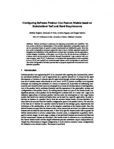
Feature-oriented domain analysis (FODA) [4] could well be termed the mother of all feature modelling methods: the authors of many other feature modelling methods presented in this report define their methods as an extension of FODA. Further, FODA is the de-facto standard reference feature modelling method. FODA was developed at the Software Engineering Institute of Carnegie Mellon University in 1990 as a method for discovering and representing commonalities among related software systems. FODA consists of three phases, namely context analysis, domain modelling, and architecture modelling. The purpose of feature modelling is to capture the end-user’s understanding of the capabilities of applications in the domain. The FODA definition for feature is an “attribute of a system that directly affects end-users”. Therefore, FODA subscribes to the first definition of feature discussed in the previous section. In FODA, features are organised into a feature diagram that is a tree. The basic relationship that can occur between features is the consists-of relation. The semantics of consists-of is that in order for a system to have or, in other words, to deliver a feature A, the system must deliver all the features of which A consists. Optional features can be used to represent the fact that a feature may, but is not required, to contain another feature. Example. Figure 1 (a) contains a FODA-style feature diagram that will be used to illustrate the concepts of FODA. Figure 1 (b) contains a legend of the notation used. The feature model depicts a simplistic feature model of a car. The Car feature consists of Transmission and Horsepower features. Further, a car may or may not contain an Air conditioning, modelled as an optional feature. ■ Alternative features can be used to represent a form a specialisation. The semantics of an alternative feature is that exactly one of the features in the set of alternative features must be selected whenever the parent of the set of alternative features is selected. Example. In Figure 1 (a), the Automatic and the Manual features can be considered as specialisations of the generic Transmission feature. The semantics is that a car must have a transmission mechanism that is either manual or automatic. ■ In addition to the above-discussed hierarchical structure of features, there can exist other elements in feature models: composition rules and rationales. Composition rules can be used to restrict the possible feature combinations. There are two kind of composition rules: requires and incompatible rules. The requires rules are of the form A requires B, and the semantics is that whenever feature A is delivered by a system, B must be delivered as well. Further, the structure of incompatible rules is A incompatible with B, and the semantics is that a system in the domain may not deliver both A and B. However, [4] is not entirely consistent with the forms composition rules may take: Figure 1 (a) includes a consistency rule that is not of the above-described form. Rationales are statements about the relations between features. Unlike composition rules above, they are not hard in the sense that they would have direct implications on the valid feature combinations induced by a model. Instead, rationale contain information about the target domain that should be taken into consideration when engineering systems in the domain. Example. The composition rule in Figure 1 (a) is a requires rule saying that at least hundred horsepowers are required from a car with air conditioning. Further, the rationale captures the fact that a car with a manual transmission is more efficient than one with an automatic one; should a customer require a fuel-efficient car, one with manual transmission should be recommended. ■
4-2
Transmission
Horsepower
Air conditioning
Composition rule: Air condition requires Horsepower > 100
Manual
Automatic
Rationale: Manual more fuel efficient (a) Alternative features A and B A
B
B
Feature B
C
Optional feature C
Consists of
(b) Figure 1.
(a) FODA-style feature model. (b) Legend of the notation. [4]
3.2 Feature-oriented Reuse Method (FORM) Feature-oriented reuse method (FORM) [5] is an extension of FODA. While FODA is mainly aimed at development for reuse, the goal being to create a set of reusable assets; FORM, in turn, is purported to cover development for reuse as in FODA and, in addition, development with reuse, i.e., the deployment of software systems in the domain of study using the assets developed. In addition, FORM includes some modelling concepts that are not present in FODA. In the following, we will discuss these concepts in some detail. FORM is authored by a group of Korean researchers from both academia and industry. Some of the authors were involved in developing FODA. A feature is defined as an essential characteristic of an application in a domain. Therefore, FORM adheres mostly to the second definition discussed in Section 2. Features are classified into four layers. A feature in the capability layer “literally characterises a distinct service, operation, function, or performance that an application (for the given domain) may possess”. Operating environment layer, in turn, contains features that “represent attributes of the environment in which an application is used and operated”. Finally, feature in the Domain technology layer, and Implementation technique layer “represent implementation details at lower and more technical levels. Three kinds of relations may exist between features: generalisation/specialisation, composed of, and implemented by. Unfortunately, neither [5] nor other papers on FORM give detailed semantics for these relations, or guidelines when to use them. However, lexically the composed-of relation seems to pertain to the consists-of relation of FODA, and to be used between features on the same layer. Further, the generalisation relation seems to represent a kind of classification between features, and likewise to be used between features on the same layer. Finally, the implementedby relation seems to be used between features on different layers. A distinction between mandatory, optional, and alternative features is made. The semantics is: a mandatory feature must exist in all applications in a given domain, whereas an optional feature may not be necessary in some applications of the domain; alternative features indicate that no more than one feature can be selected for an application from each set of alternative features. [10]
Capability layer
Service
... Public message board Edit
Operating environment layer
S/W structure
Distributed
Centralised
Domain technology layer Full screen edit
Implementation technique layer Full screen editor
vi
pico
Door
Gateway door
Captive door
(a) Mandatory feature
Distributed
Optional feature
Door
Alternative feature vi
pico
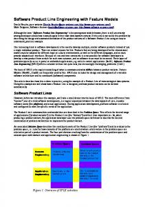
Generalisation/specialisation Composed of Implemented by (b) Figure 2. (a) FORM-style feature model (b) Legend of the notation used. Adapted from [5].
Example. Figure 2 (a) contains a FORM-style feature model; Figure 2 (b) contains a legend of the notation used. In Figure 2 (a), there is a generalisation/specialisation relation between the features vi and Full screen editor and pico and Full screen editor. The semantics is that both vi and pico are Full screen editors. Further, there is an implemented-by relation between the features Full screen edit in the Domain technology layer, and Full screen editor in the Implementation technique layer. ■ An important observation that can be made based on Figure 2 is that the structure (in terms of the union of all three relations) of the feature model is not a tree, but rather a forest. Example. In Figure 2 (a), neither of the features Door and S/W structure have a parent feature in any of the three relations. ■
3.3 Czarnecki et al. Czarnecki and a number of other researchers have presented their view of what features are [6,7]. For simplicity, we refer to this
4-3
group of researchers as Czarnecki in the following. Similarly as FORM, their conceptualisation of features is based on FODA. The work done by Czarnecki related to features is part of their work in developing a new programming paradigm called generative programming; generative programming is a set of programming techniques that aim at automating the software development process when deploying systems in a family or systems, or a domain [6]. Therefore, the background of the work of Czarnecki is similar to that of the authors of FODA and FORM. This section on Czarnecki’s work is structured as follows. First, we present the conceptualisation of features presented in [6] as the baseline for Czarnecki’s view on features. Thereafter, we discuss the extensions made to the conceptualisation in [7]. Czarnecki follows the second definition for feature: a feature is a distinguishable characteristic of a concept that is relevant to some stakeholder of the concept. Thus, in Czarnecki’s view, features are related to concepts. A concept is any element or structure that is of interest in the domain of study. A feature model represents the common and the variable features of concept instances, and the dependencies between the variable features. A feature model consists of a feature diagram and additional information: descriptions of each feature, stakeholders and client programs related to features, default dependency rules, binding sites and times, etc. In the following, we will discuss the information that is represented using feature diagrams; the interested reader should refer to [6] for additional information. The structure of a feature diagram must be a rooted tree. The root of the tree is a concept. The children nodes of the concept are features. The children of features are called subfeature. Unlike in FODA and FORM above, the edges of the feature diagram are not given any semantics as such; they simple define a tree, and the semantics of a feature diagram is defined in terms of the tree. In common terms, the semantics of the edges is close to that of composition. Featural descriptions of a concept can be derived from the feature diagram. A featural description is a set of features, and the semantics is that the concept provides exactly the features contained in the description. Czarnecki categorises features as mandatory, optional, alternative, and or-features. A mandatory feature is included in the description of a concept instance if and only if its parent is included in the description of the instance. On the other hand, an optional feature may be included in the description of a concept instance if and only if its parent is included in the description. That is, the inclusion of a parent of an optional feature gives the option of including the optional feature. Example. Figure 3 (a) depicts a simple feature diagram with mandatory and optional features; legend of the notation used is in Figure 3 (b). In the diagram, concept C has two features, f1 and f4. Of these, f1 is a mandatory feature and f4 an optional one. Further, features f1 and f4 have subfeatures: f1 has a mandatory subfeature f2 and an optional subfeature f3; f4 has the mandatory subfeature f5. ■ Alternative features are grouped into non-empty sets. For each set of alternative features, if the parent of the set is included in the description, exactly one of the features in the set of alternative features must be included in the description of the concept instance. Finally, the semantics of an or-feature is similar to those of alternative features; the difference is that whereas the inclusion of a parent of a set of alternative features implies that exactly one of the features in the set must be included, for a set of or-features at least one must be selected. That is, two, three or even all the features in the set can be included in the description of the concept instance.
C’
C
f4
f1
f11 f3
f2
f13
f14
f15
(a)
f5
Alternative feature
(a) f2
f12
Or-feature (b)
Mandatory feature
f3
Optional feature
Figure 4. Alternative and or-features (a) Sample feature diagram (b) Legend of the notation used
(b) Figure 3 Mandatory and optional features. (a) Sample feature diagram (b) Legend of the notation used.
Example. Figure 4 (a) contains a feature diagram with alternative and or-features; Figure 4 (b) contains a legend of the notation used. The semantics of the diagram is that an instance of C’ has one of the features f11, f12, and f13, and at least one of f14 and f15. That is, { f11, f14, f15} is a valid combination of features, whereas { f11, f12, f15 } and { f11 } are not. ■ There are composition rules and rationales in Czarnecki’s feature modelling conceptualisation. The form and semantics of these constructs is the same as in FODA: a feature may require another, or a pair of feature may be mutually exclusive. Rationale are the soft form of composition rules. In [7], Czarnecki extends the feature modelling concepts presented above with cardinalities, attributes, and reference attributes. Cardinalities are used to specify the required number of a given subfeatures in a description of a concept instance. The semantics of cardinality is probably most easily understood by stating that a mandatory feature corresponds to cardinality 1, and an optional one to cardinality 0 to 1. In a set of alternative or or-features, each subfeature in the set is specified a cardinality of its own. The semantics is that if a subfeature is selected, the number of subfeatures must be within the cardinality bounds. Especially, if zero is included in the cardinality, zero features may be selected. Attributes are another extension mechanism. The idea is that features can contain additional information in the form of attributes, similarly as UML (Unified Modeling Language) classifiers can contain attributes. An attribute defines a name and a type. The motivation for attributes is that they enable more concise knowledge representation; the alternative would be to use subfeatures. Further, unlike features, attributes can be defined types: e.g. enumeration attributes enable the compact representation of a fixed range of values. Finally, features can contain reference attributes. A reference attribute parameterises a feature with another feature. In addition to name and type, a reference attribute includes a cardinality. The exact semantics of reference attributes is not specified in [7].
4
COMPARISON
In this section, we compare the feature modelling methods analysed above with the configuration ontology presented in [8]. In the following, we use the term configuration ontology when referring to this particular ontology.
4.1 Key Concepts and Relations The notion of feature is virtually the only ontological commitment that any of the feature modelling methods studied makes. The configuration ontology, on the other hand, does not include a concept with the same name. However, the configuration ontology does include a large number of other concepts (components, ports, resources, functions, constraints, contexts); it is worth studying, whether one of these would be equivalent or similar to features. The essence of features is that they can be related to other features. In FODA and in Czarnecki’s method, the semantics of the relation between features are similar: a feature, let us call it parent feature is related to a number of other features, or possibly sets of features (alternative and or-features). The well-formedness criterion is that whenever the parent feature is selected (included in a feature description), the related features must be selected as well. Hence, the semantics of the relation is a form of composition. In FORM, the semantics of optional features is different: an optional feature is a feature that may not be necessary in some applications of a given domain. In configuration ontology, there are two concepts that can be self-composed: components and functions. However, neither components nor functions are equivalent to features. First, in the configuration ontology, a distinction between types and instances is made for both components and functions; no similar distinction is made for features in any of the feature modelling methods analysed. Second, in a configuration (of a configuration model) each part of a component (function) has a designated role described by a name. For features, there is no similar name; on the other hand, each feature has a unique name. Finally, both component and feature instances in the ontology may have multiple parts with the same name; for features, this is only possibly in the extended version of Czarnecki’s modelling method.
4.2 Modelling Variability In this subsection, we first compare the mechanisms for modelling variability provided by the feature modelling methods to those of the configuration ontology. As a special case, we iterate on the constraint mechanisms embedded in them. FODA and Czarnecki’s feature modelling method provide similar mechanisms for modelling variability within the feature hierarchy, namely optional and alternative features, and Czarnecki additionally or-features and cardinalities. The configuration ontology, on the other hand, includes the possibility to specify cardinal-
4-4
ities in part definitions in both component and function types, and to specify multiple possible part types. There is a degree of similarity between these mechanisms. Both Czarnecki and the configuration ontology include cardinalities; optional and alternative parts are a special case of cardinalities and multiple possible part types. However, there is a fundamental difference in the semantics of in these methods: for Czarnecki, each feature in an alternative and or-feature set has a cardinality of its own. In the configuration ontology the cardinality definition is a property of a part definition, and the rule is that the number of each possible type must sum up to be within the cardinality bounds. Compared with the feature modelling concepts, configuration ontologies include more concepts that can be used for modelling variability: in addition to the possibility of modelling both components and functions, it is possible to model their interdependencies, ports (connection points of components), and resources. Both FODA and Czarnecki’s method include constraints as a modelling primitive; FORM does not discuss them explicitly. Constraints are of the form A requires B and A incompatible with B. In addition, it is possible to write rationale. They have the same form as constraints but are soft in the sense that disobeying them does not invalidate a configuration. The configuration ontology includes constraints as well, and their intended purpose is similar to the constraints in the two feature modelling methods: express conditions on configuration that cannot be reasonably expressed using other modelling constructs. Configuration ontology [8] itself does not explicate the kind of constraint that may be written, but, e.g., WeCoTin [11], an academic prototype configurator, allows writing constraints with references to the part structure of components and their attributes, and such references can be combined using standard propositional connectives. The configuration ontology does not include a notion similar to rationale. However, other work in the configuration domain has discussed soft constraints, notion similar to rationale.
4.3 Distinction between Types and Instances In the configuration ontology of [8], and in configuration modelling in general, the distinction between types and instances is one of the fundamental constituents of modelling methods. However, in the feature modelling methods studied, no such distinction is made.
5
REPRESENTING FEATURE MODELS USING PRODUCT CONFIGURATION CONCEPTS
In this section, we suggest a translation from the feature modelling concepts to those of the configuration ontology. In more detail, we will show how different concepts and relations in feature modelling methods are translated into configuration modelling concepts. Above, we pointed out that of the configuration modelling concepts, both components and functions could seemingly be used to capture features. At this point, we make the (arbitrary) choice to model feature with components. Features are translated into component types. A root feature type is translated into an independent component type, i.e., a component type the instances of which may be in valid configuration without being a part of some other instances; all other features are translated into dependent component types. The name of the feature becomes the name of the type. Subfeature-relationships (consists-of etc.) between features are translated into part definitions. We use the terms whole-feature and subfeature to refer to the feature containing a subfeature and the subfeature, respectively. The part definition is located in the com-
ponent type corresponding to the whole feature. The name of the part definition is the name of the subfeature. Cardinality is 1, if and only if the subfeature is mandatory, and 0..1 if the subfeature is optional. The set of possible part types contains a single type, namely the component type to which the subfeature is translated. Alternative features, as defined in FODA, are translated into part definitions. At this point, there is no obvious choice for the name of the part definition. The set of possible types consists of the types corresponding to the features in the set. Cardinality has always value one. There is no straightforward translation for alternative and orfeatures as defined by Czarnecki. The reason for this is the discrepancy in the use of cardinalities in [8] and [7], see above. Consequently, each feature in a set is translated like a single feature; we call the set of part definitions thus resulting g. Additionally a constraint is added with the following semantics: exactly (at least) one of the part definitions in g must have a cardinality within its bounds, and the remaining definitions must have cardinality zero. Attributes, as defined in Czarnecki’s method [7], can be translated into attribute definitions in component types. The name of the attribute definitions is simply the name of the attribute.
6
DISCUSSION, PREVIOUS WORK
In this section, we first discuss some issues, and thereafter compare our work to previous work. The fact that feature modelling methods make minimal ontological commitments results in anomalies when translating feature models into configuration modelling concepts. As an example, let us consider the translation of alternative parts: above, they were translated into multiple possible part type. However, sometimes translating them into is-a relations between types would be more appropriate: e.g., in Figure 1 (a), Automatic and Manual form a set of alternative subfeatures of Transmission. In this case, the intuitive semantics is that automatic and manual are kinds of transmission mechanisms, not parts of any transmission. On the other hand, it is intuitively clear that in some cases translating alternative feature sets into multiple possible part types is the most natural translation. Consequently, any formulaic translation from feature models to configuration complex will result in counterintuitive models. There seems to be no universal solution to the question whether to use components or functions for modelling features; the example in Figure 2 illustrates this point. Features located on lower layers, such as Vi or Pico, should intuitively be modelled as components, whereas features on higher layers, e.g., Public message board, seem to represent functions. To the best of our knowledge, feature modelling methods have previously not been compared with configuration modelling concepts. Consequently, we consider this to be the main contribution of our work. However, related research has been conducted earlier. A number of authors have considered the configuration of feature models, i.e., the problem of finding a combination of features matching specific customer requirements. Beuche et al. have introduce an approach called CONSUL for creating and configuring feature models [12]. In their approach, software product families are modelled not only using features, but components as well. In this sense, their approach resembles the coexistence of components and functions in configuration ontologies. However, what seems to differentiate their work from knowledge-based configuration is the lack of automated inference and its advantages. Some authors have acknowledged the need for supporting the user in the configuration process. In [13], von der Maßen et al.
4-5
introduce RequiLine, a requirements engineering tool for software product families. The intended functionality includes checking a feature configuration with respect to some well-formedness criteria, and supporting the customer in the configuration task. In [6], Czarnecki et al. describe cases in which valid configurations adhering to user-provided parameters can be automatically achieved. These cases are based on encoding the knowledge about valid configurations as procedural knowledge. The interrelations of software product families and configurable products have been studied earlier. Männistö et al. have pointed out the existence of the research area of configurable software and identified some key concerns within it [14]. Further, Hein and MacGregor [15] iterated on the idea of applying knowledge-based configuration techniques to software product families. However, they have not presented a holistic solution to the problem, or analysed the compatibility of the underlying conceptual bases. Similarly, Krebs and Hotz have iterated on the same idea, but have not given a detailed account about what concepts would be used for modelling software product families, and how would these be related to those intended for modelling configurable products. [16] In [17], Asikainen et al. study Architecture Description Languages (ADLs) and compare their underlying concepts with the configuration modelling concepts, using a research approach that is highly similar to that applied in this paper. However, what differentiates our work from theirs is that feature models and architectural models described using ADLs are complementary ways to describe software product families: while features can be used to describe software systems from various, even arbitrary viewpoints, ADLs typically have a much more restricted focus. Christian Kühn has presented an approach to configuring software based on its structure and behaviour [18]. However, neither of these dimensions is equivalent to feature models.
7
CONCLUSIONS AND FUTURE WORK
Above, we have presented an analysis of three feature modelling methods and compared their concepts to a configuration ontology. The aim has been to identify commonalities and differences between the concepts used for feature modelling and modelling configurable products, and exploiting the commonalities, to apply existing tools and techniques to configuring software. We found that both the concept of component and function, as defined in [8], are similar to the concept of feature found in feature modelling methods: most importantly, components, features, and functions can all be defined a compositional structure in terms of themselves. This observation enabled us to outline a translation from feature models to components. Although such a translation is encouraging with respect to the goal of transferring results from the configuration domain to software engineering domain, it is not a triviality: the translation is unintuitive in the sense that it is not always obvious, which configuration modelling concept is the most appropriate for representing, e.g., alternative features. There are a large number of closely related unresolved problems related to the topic of this paper. As a first step, a conceptual basis for configuring software product families based on features should be created by synthesising the existing feature modelling methods with the configuration modelling concepts. Thereafter, modelling languages, both textual and graphical ones, should be built based on these conceptualisations. Using these, it would be possible to try to apply existing modelling and configuration tools to software product families described in terms of their features, or to develop new ones. The practical applicability of the modelling method should be
analysed by applying the preceding constructs in case companies. Finally, as the computational tasks related to configuration are potentially very complex, the computational feasibility of configuring software should be analysed through practical experiments and theoretical complexity analysis.
ACKNOWLEDGEMENTS We gratefully acknowledge the financial support from the Academy of Finland (project number 51394) and National Technology Agency of Finland (Tekes).
REFERENCES [1] P. C. Clements and L. Northrop, Software Product Lines - Practices and Patterns, Addison-Wesley, 2001. [2] J. Bosch, Design and Use of Software Architectures: Adapting and Evolving a Product-Line Approach, Addison-Wesley, 2000. [3] M. Raatikainen, T. Soininen, T. Männistö, and A. Mattila, ‘A Case Study of Two Configurable Software Product Families’, in: Proceedings of the 5th International Workshop on Product Family Engineering (PFE-5). Lecture Notes in Computer Science 3014, 2004. [4] K.Kang, S.G.Cohen, J.A.Hess, W.E.Novak, and S.A.Peterson, Feature-Oriented Domain Analysis (FODA) - Feasibility Study. Technical report CMU/SEI-90-TR-21, Carnegie-Mellon University, 1990. [5] K. Kang, S. Kim, J. Lee, et al, ‘FORM: A Feature-Oriented Reuse Method with Domain-Specific Reference Architectures’, Annals of Software Engineering, 5, 143-168, (1998). [6] K. Czarnecki and U. W. Eisenecker, Generative Programming, Addison-Wesley, 2000. [7] K. Czarnecki, T. Bednasch, P. Unger, and U. W. Eisenecker, ‘Generative Programming for Embedded Software: An Industrial Experience Report’, in: Proceedings of GPCE, 2002. [8] T. Soininen, J. Tiihonen, T. Männistö, and R. Sulonen, ‘Towards a General Ontology of Configuration’, AI EDAM, 12, 357-372, (1998). [9] A. Felfernig, G. Friedrich, and D. Jannach, ‘UML as Domain Specific Language for the Construction of Knowledge-Based Configuration Systems’, International Journal of Software Engineering and Knowledge Engineering, 10, 449-469, (2000). [10] K. Lee, K. Kang, W. Chae, and B. W. Choi, ‘Feature-Base Approach to Object-Oriented Engineering of Applications for Reuse’, Software Practice and Experience, 30, 1025-1046, (2000). [11] J. Tiihonen, T. Soininen, I. Niemelä, and R. Sulonen, ‘A Practical Tool for Mass-Customising Configurable Products’, in: Proc. of ICED, 2003. [12] D. Beuche, H. Papajewski, and W. Schröder-Preikschaft, ‘Variability Management with Feature Models’, in: Proc. of Software Variability Management Workshop. IWI preprint 2003-7-01, Univ. of Groningen, 2004. [13] T. von der Maßen and H. Lichter, ‘RequiLine: A Requirements Engineering Tool for Software Product Lines’, in: Proc. of 5th International Workshop on Product Family Engineering, LNCS 3014, 2004. [14] T. Männistö, T. Soininen, and R. Sulonen, ‘Product Configuration View to Software Product Families’, in: Proc. of 10th Int. Workshop on Software Configuration Management (SCM-10) of ICSE, 2001. [15] A. Hein and J. MacGregor, ‘Managing Variability with Configuration Techniques’, in: Software Variability Management Workshop of ICSE’03, 2003. [16] T. Krebs and L. Hotz, 'Needed Expressiveness for Representing Features and Customer Requirements’, in: ECOOP 2003 Workshop on Modeling Variability for Object-Oriented Product Lines, 2003. [17] T. Asikainen, T. Soininen, and T. Männistö, ‘Representing Software Product Family Architecture Using a Configuration Ontology’, in: Configuration workshop of ECAI, 2002. [18] C. Kühn, ‘Modeling Structure and Behavior for Knowledge-Based Software Configuration’, in: Proc. of ECAI 2000 Workshop on New Results in Planning, Scheduling, and Design, 2000.
4-6