National Aeronautics and Space Administration AT01S George C. Marshall Space Flight Center Marshall Space Flight Center, Alabama 35812
NASA/TP—1998–208530
Reusable Rocket Engine Operability Modeling and Analysis R.L. Christenson and D.R. Komar Marshall Space Flight Center, Marshall Space Flight Center, Alabama
July 1998
The NASA STI Program Office…in Profile Since its founding, NASA has been dedicated to the advancement of aeronautics and space science. The NASA Scientific and Technical Information (STI) Program Office plays a key part in helping NASA maintain this important role. The NASA STI Program Office is operated by Langley Research Center, the lead center for NASA’s scientific and technical information. The NASA STI Program Office provides access to the NASA STI Database, the largest collection of aeronautical and space science STI in the world. The Program Office is also NASA’s institutional mechanism for disseminating the results of its research and development activities. These results are published by NASA in the NASA STI Report Series, which includes the following report types: • TECHNICAL PUBLICATION. Reports of completed research or a major significant phase of research that present the results of NASA programs and include extensive data or theoretical analysis. Includes compilations of significant scientific and technical data and information deemed to be of continuing reference value. NASA’s counterpart of peer-reviewed formal professional papers but has less stringent limitations on manuscript length and extent of graphic presentations. • TECHNICAL MEMORANDUM. Scientific and technical findings that are preliminary or of specialized interest, e.g., quick release reports, working papers, and bibliographies that contain minimal annotation. Does not contain extensive analysis. • CONTRACTOR REPORT. Scientific and technical findings by NASA-sponsored contractors and grantees.
• CONFERENCE PUBLICATION. Collected papers from scientific and technical conferences, symposia, seminars, or other meetings sponsored or cosponsored by NASA. • SPECIAL PUBLICATION. Scientific, technical, or historical information from NASA programs, projects, and mission, often concerned with subjects having substantial public interest. • TECHNICAL TRANSLATION. English-language translations of foreign scientific and technical material pertinent to NASA’s mission. Specialized services that complement the STI Program Office’s diverse offerings include creating custom thesauri, building customized databases, organizing and publishing research results…even providing videos. For more information about the NASA STI Program Office, see the following: • Access the NASA STI Program Home Page at http://www.sti.nasa.gov • E-mail your question via the Internet to
[email protected] • Fax your question to the NASA Access Help Desk at (301) 621– 0134 • Telephone the NASA Access Help Desk at (301) 621–0390 • Write to: NASA Access Help Desk NASA Center for AeroSpace Information 800 Elkridge Landing Road Linthicum Heights, MD 21090 –2934
NASA/TP—1998 –208530
Reusable Rocket Engine Operability Modeling and Analysis R.L. Christenson and D.R. Komar Marshall Space Flight Center, Marshall Space Flight Center, Alabama
National Aeronautics and Space Administration Marshall Space Flight Center
July 1998 i
Acknowledgments Many made contributions directly and indirectly to this effort that are much appreciated. These include Robert Beil, Ron Liston, Jennifer Ringelberg, Richard Brown, William D. Morris, Edgar Zapata, Russ Rhodes, Michael Nix, Fred Huffaker, and Barney Holt. A special thanks to Richard Ryan, who supported the requirements definition and to Bruce Fleming, who supported the extensive data collection necessary to conduct these analyses.
Available from:
NASA Center for AeroSpace Information 800 Elkridge Landing Road Linthicum Heights, MD 21090–2934 (301) 621–0390
National Technical Information Service 5285 Port Royal Road Springfield, VA 22161 (703) 487–4650
ii
TABLE OF CONTENTS
1.
INTRODUCTION ...................................................................................................................
1
2.
BACKGROUND .....................................................................................................................
3
3.
OPERABILITY ASSESSMENT METHODOLOGY .............................................................
4
A. Approach ............................................................................................................................. B. Key Concepts and Definitions ............................................................................................ C. Modeling and Uncertainty .................................................................................................. D. Process Flow Definition .....................................................................................................
4 7 8 9
4.
MODELING TOOLS ..............................................................................................................
10
5.
BASELINE ENGINE OPERATIONS DATA .........................................................................
11
A. Data Collection ................................................................................................................... B. Scheduled Processing ......................................................................................................... C. Unscheduled Processing ..................................................................................................... D. Baseline Requirements Database ........................................................................................
11 12 15 17
MODEL DEVELOPMENT AND RESULTS .........................................................................
19
A. Deterministic Model ........................................................................................................... B. Probabilistic Model .............................................................................................................
20 23
CONCLUSIONS .....................................................................................................................
32
Appendix A—Engine Operations Requirements Database .................................................................
33
Appendix B—Scheduled SSME Operations Data...............................................................................
45
Appendix C—Unscheduled SSME Operations Data ..........................................................................
66
Appendix D—Pertinent SSME Results From Analysis of Data Collected .........................................
73
Appendix E—Reliability of Engine Sets With Engine Out Capability ...............................................
77
REFERENCES ....................................................................................................................................
80
6.
7.
iii
LIST OF FIGURES
1.
Disciplines in design ...................................................................................................................
1
2.
Launch vehicle process flow—operational phase ......................................................................
4
3.
Operability assessment methodology .........................................................................................
5
4.
Design-to-operations analysis approach .....................................................................................
7
5.
Operations modeling and data collection process ...................................................................... 11
6.
OPF SSME postflight operations ............................................................................................... 12
7.
OMEF SSME operations ............................................................................................................ 13
8.
OPF post-SSME installation operations ..................................................................................... 13
9.
SSME VAB/pad processing operations ...................................................................................... 14
10.
Example of detailed model—HPFTP removal and replace ........................................................ 14
11.
SSME base R&R ........................................................................................................................ 16
12.
Requirements to process definition ............................................................................................ 17
13.
Engine operations processing ..................................................................................................... 20
14.
Hierarchical engine model .......................................................................................................... 21
15.
Extend reusable engine operations model .................................................................................. 25
16.
Operability measures by process time ........................................................................................ 28
17.
Impact of reliability on operability ............................................................................................. 29
18.
Operability metrics by reliability ................................................................................................ 29
19.
Engine operations manhours/cost analysis ................................................................................. 30
20.
Base MR accept .......................................................................................................................... 66
iv
LIST OF FIGURES (Continued)
21.
Base MR repair ........................................................................................................................... 66
22.
Base PR accept ........................................................................................................................... 67
23.
Base PR repair ............................................................................................................................ 67
24.
Base waiver/exception ................................................................................................................ 67
25.
Total SSME manhours by process type ...................................................................................... 73
26.
Scheduled SSME manhours by process type ............................................................................. 74
27.
Unscheduled SSME manhours by process type ......................................................................... 75
28.
SSME manhours by process type ............................................................................................... 76
v
LIST OF TABLES
1.
SSME PR classification summary .............................................................................................. 15
2.
OMRSD/OMI database with requirements rationale ................................................................. 17
3.
SSME unscheduled maintenance experience ............................................................................. 22
4.
Goal-oriented engine operations timelines ................................................................................. 23
5.
Results of probabilistic analysis ................................................................................................. 27
6.
Probabilistic model uncertainty impact ...................................................................................... 28
7.
Engine processing manhours and launch delay reduction .......................................................... 30
8.
Engine requirements database .................................................................................................... 34
9.
OPF SSME postflight planned operations .................................................................................. 46
10.
OMEF SSME planned operations .............................................................................................. 47
11.
OPF post-SSME installation planned operations ....................................................................... 48
12.
SSME VAB/pad processing planned operations......................................................................... 49
13.
OPF rollin to SSME removal tasks ............................................................................................ 50
14.
Engine shop turnaround tasks ..................................................................................................... 55
15.
Engine installation to OPF rollout tasks ..................................................................................... 56
16.
VAB rollin to launch tasks .......................................................................................................... 60
17.
Example of detailed data for scheduled processing in OMEF ................................................... 65
18.
SSME unscheduled processing summary ................................................................................... 68
19.
Example of detailed data for unscheduled processing................................................................ 72
20.
Engine out capability comparison .............................................................................................. 77
21.
Engine out and time of engine out comparison .......................................................................... 79
vi
ACRONYMS
CAPSS DAR ELV EMA gox GSE HPFTP
Computer-Aided Planning and Scheduling System deviation approval request expendable launch vehicles electromechanical actuator gaseous oxygen ground support equipment high-pressure fuel turbopump
HPOTP Isp
high-pressure oxidizer turbopump
KSC LH2 LO2 MDT MR MS MSFC MTBF MTBM MTTR NASA OMEF OMI OMRSD OPF PR PRACA R&R RLV SSME STS TVCA VAB
specific impulse Kennedy Space Center liquid hydrogen liquid oxygen mean downtime material review Microsoft® Marshall Space Flight Center mean time between failure mean time between maintenance mean time to repair National Aeronautics and Space Administration orbiter main engine facility Operations and Maintenance Instructions Operations and Maintenance Requirements and Specification Document orbiter processing facility problem report Problem Reporting and Corrective Action remove and replace reusable launch vehicle space shuttle main engine Space Transportation System thrust vector control assembly vehicle assembly building
vii
TECHNICAL PUBLICATION REUSABLE ROCKET ENGINE OPERABILITY MODELING AND ANALYSIS
1. INTRODUCTION
The reusable launch vehicle (RLV) cooperative development program between NASA and the aerospace industry demands the design of cost-effective vehicles and associated propulsion systems. In turn, cost-effective propulsion systems demand minimal and low recurring costs for ground operations. Thus, the emphasis early on in this program should be effective operations modeling supported by the collection and use of applicable operations data from a comparable existing system. Such a model could support the necessary trades and design decisions toward a cost-effective propulsion system development program. These analyses would also augment the more traditional performance analyses in order to support a concurrent engineering design environment.1–4 In this view, functional area analyses are conducted in many areas including operations, reliability, manufacturing, cost, and performance, as presented in figure 1. The design engineer is responsible to incorporate the input from these areas into the design where appropriate. The designer also has the responsibility to conduct within and between discipline design trades with support from the discipline experts. Design decisions without adequate information from one or more of these areas results in an incomplete decision with potential serious consequences for the hardware. Design support activities in each functional area are the same. Models are developed and data are collected to support the model analysis. These models and data are at an appropriate level of detail to match the objectives of the analysis. Metrics are used in order to quantify the output. This is an iterative approach that supports the design schedule with results updated from increasingly more detailed design information.
Cost
Performance
Design
Operations
Manufacturing Reliability
Figure 1. Disciplines in design.
1
Currently, in aerospace applications, there is a mismatch between the complexity of models (as supported by the data) within the various disciplines. For example, while good engine performance models with accurate metrics exist, the use of absolute metrics of reliability for rocket engine systems analysis is rarely supported. This is a result of the lack of good test data, lack of comparable aerospace systems, and a lack of comparative industrial systems relative to aerospace mechanical systems. Metrics also tend to be less credible for reliability. There is, as yet, not a comparable reliability metric that would allow one to measure and track reliability as the engine specific impulse (Isp) metric allows one to measure and track engine performance. Performance models such as an engine power balance model or a vehicle trajectory model tend to be of good detail, with a good pedigree, and the results well accepted by the aerospace community. The propulsion system designer has to be aware of these analysis fidelity disparities when it becomes necessary to base a design decision on an analysis. There is a need to develop models to obtain different objectives. Early in a launch vehicle development program, a top-level analysis serves the purpose of defining the problem and securing top-level metrics as to the feasibility and goals of the program. This “quick-look” model effort serves a purpose—it often defines the goals of the program in terms of performance, cost, and operability. It also is explicit about the need to do things differently in terms of achieving more stringent goals. A detailed bottom-up analysis is more appropriate to respond to the allocation based on an indepth study of the concepts. The “quick-look” model is appropriate if the project manager is the customer; the detailed analysis is directed more at the design engineer. Both are of value. The “quick-look” model also may serve the purpose of the allocated requirements model, the model to which comparisons are made to determine maturity of the design. It is inappropriate to use the data that supported the allocation of requirements to also support the detailed analysis. Although often done, this is inappropriate and could lead to misleading results. The acquisition of good data is a traditional problem for the definition of baseline systems for aerospace launch vehicle operations analyses. For all models developed here, the Space Transportation System (STS) and the space shuttle main engine (SSME) are used as the source of historical reusable vehicle and engine systems operations experience. For the detailed model, the approach demands the identification of the requirements for SSME ground operations and the root source of the requirements. From this, a reusable engine model is developed that is based on the SSME operations model. This is done through incremental modification of the baseline operations model based on the proposed changes from the SSME to the reusable engine. The modifications of these processing activities are based on changes in hardware configuration and technology, processing technology improvements, and operations philosophy. The reusable engine system model is then traceable to past requirements and historical experience. This modeling approach supports credible operations modeling and analysis. In this paper, the baseline SSME model and a demonstration of its utility are presented.
2
2. BACKGROUND
The lack of historical data in support of aerospace launch vehicle operations analyses is acute. Data are either unavailable due to not being collected or not public, or are so highly aggregated as to mask needed detail at the process level. Top-level models generated by existing data were generally useful only for supporting programmatic goal discussions. Discrete event simulation models have often been models of choice.5–7 One approach to aerospace launch vehicle operations analyses is to compare with aircraft data. This information is generally more readily available and in the proper format with data collected from a maintainability point of view. Several papers have taken this approach.8,9 While this data supports good model development, the question of applicability of results is more of an issue. This is especially true of rocket and aircraft propulsion systems with major differences in configurations, environment, and operating philosophy. Specifically, these differences include operating environment; operating temperatures, pressures, and thrust; ability to idle, taxi, and loiter aircraft engines and vehicles; use of cryogenic fuels on rockets; large performance margins on aircraft; nonintrusive health management of aircraft propulsion systems; and, perhaps the major difference, a philosophy of use with aircraft that tolerates test and operational failures (and even loss of life). Ground operations analyses have also been conducted for aerospace launch vehicles based on available STS operations data.10,11 Although the available data were found to be insufficient,12 existing databases can be augmented by other sources, such as the experience of launch site personnel. This study builds on this approach. The SSME is regarded as the most directly applicable baseline for comparison with future and similar liquid oxygen (LO2)/liquid hydrogen (LH2) rocket systems. Thus, for this effort, extensive data collection was undertaken for STS propulsion systems to augment the existing databases. A baseline set of propulsion systems ground operations databases has been developed with the goal of supporting detailed engineering analyses of process and manpower requirements for future propulsion system concepts.
3
3. OPERABILITY ASSESSMENT METHODOLOGY
A. Approach The operability assessment methodology described in this document reflects an end-to-end process flow model that models the uncertainties inherent in the attributes of the process flows. This approach attempts to substitute a rigorous and objective structure for more qualitative types of judgments and to focus design experiences to help determine areas of design confidence. It is to be used upfront in the design process and combines past flight vehicle experiences with design analysis to determine cost and schedule parameters of interest. It can be used in the analysis of any process flow where the goal is to optimize processing in order to minimize cost and schedule impacts. The continuum of process flow activities includes development through manufacturing, assembly, and operations. For this modeling effort, the emphasis will be on the operational phase only. Figure 2 presents the flows of the operational phase of a launch vehicle, a subset of which will be the focus of this analysis.
Mission Requirements
Mission Planning
Sustaining Engineering
Manufacturing and Refurbishment
Assembly and Checkout
Launch Operations
Flight
Recovery
Evaluation
Evaluation
Evaluation
Evaluation
Evaluation
Vendor and Part Obsolescence
Figure 2. Launch vehicle process flow—operational phase.
4
The process flow model avoids estimates of cost and schedule parameters based upon nonspecific design characteristics such as weight and the use of integration “scale factors.” In this modeling effort, cost and schedule indicators will be based upon realistic, high-fidelity process flows targeted against the current design configuration. This approach incorporates past vehicle development experiences in terms of experience databases. These are critical parts of this methodology and are explicitly included in the approach. Since it is often difficult to obtain historical data to support these design decisions, a significant effort was undertaken to identify, incorporate, and appropriately structure this information for use with the process flow model. Figure 3 presents the input flowing to the proposed process flows of a new launch vehicle. The new vehicle requirements and design configuration contribute in the definition of flows as does information gathered relative to historical launch vehicle flows. Data and requirements that are applicable from past launch and flight vehicles, including aircraft, expendable launch vehicles (ELV’s), and the STS, may be used to generate or edit proposed flows and will be the main source of what is required (attributes) by these process flows in terms of manpower and schedule. The design and proposed flows will be continually updated, thus the approach is iterative. Also, historical data will be useful in providing insight into the traditional problems associated with the proposed process flow. Finally, new systems may require certain technology or special analyses to determine the operability of the system. This is also input to the process flow definition process. All of this information is, of course, subject to adaptation and interpretation by the design, manufacturing, and operations engineers. These groups and others must be involved at the outset in order for this to be a truly concurrent engineering effort.
Low-Level Analyses
Model Development Activities
Trade Studies Vehicle Configuration – Requirements and Design
Technology Requirements
Flight Vehicle Requirements Docs Other Delta Lessons Learned
Vehicle Proposed Process Flows and Attributes
Atlas Titan
Process Flow Modelng
Similarity & Engineering Judgment
STS
Quantifiable Performance Measures
Flight Vehicle Experience Databases
“Operability Assessment”
Other Delta Atlas Titan STS
Operability Allocation Design Alternatives End-to-End Performance Measures
Figure 3. Operability assessment methodology.
5
The lessons learned on other vehicles implicitly affects current design engineering efforts and also serves to organize the search for applicable historical data. For example, the problems of past hydraulic systems on flight vehicles may cause the design engineer to attempt to include an electromechanical actuator (EMA) subsystem into the current design. Also, this “lesson learned” can serve to organize the identification of historical process flows, requirements, and experiences. Organized appropriately, historic processes associated with hydraulics can be easily pulled from the database, thus facilitating the analysis of this problem area by an appropriate design engineering team. This step of the methodology involves more of a qualitative assessment than a quantitative one. However, there is a structure surrounding the use of “lessons learned” that reflects the need to evolve and iterate this process with the “lesson learned” information. Once the process flows and associated attributes have been defined, the modeling of the flows to generate quantifiable performance measures can be supported. The probabilistic nature of the system is clear due to the uncertain environment. Sensitivity studies, design change studies, and operability assessment studies are all supported. A top-down approach is utilized in identifying and tracing process flows. At the outset, this hierarchical method is useful in identifying major cost and schedule drivers and assists in the allocation of scarce resources in the further analysis of the lower-level process flows. The danger of low-level analyses is the danger of misallocation of scarce resources to analyses that are not clearly important cost or schedule drivers. A top-down approach creates traceability of functional flows at each level in the hierarchy. It also serves to document and allocate the top-level program requirements. Its usefulness is limited to a “quicklook” analysis and for comparison purposes with the detailed analyses. This methodology is designed to incorporate results from bottom-up analyses. Systematic evaluations of low-level process flows in terms of cost and schedule attributes will feed a detailed modeling activity. Once both models exist and comparisons are supported, both goals and actual timelines are subject to change: the top-down apportionment can be reallocated or changed; and the bottom-up reanalyzed and adapted to design changes resulting from changes incorporated into the design influenced by this modeling activity. Given this approach, the initial emphasis of this effort will be on supporting relative comparisons among design changes. Upon completion of an appropriate level of detail, accurate estimates can be generated. Figure 4 provides an overview of this two-pronged approach. First, a goal timeline is created from a future launch vehicle operations concept. Making this goal reflect an actual design is desirable if such a design exists. However, these are goals, and as such, are meant as comparison points for a bottom-up engineering analysis of a historical baseline system. The second prong is this bottom-up effort, which provides an experience base and supports traceability to design, technology, and process improvements for the future launch vehicle propulsion system. This bottom-up effort is the focus of this paper. A previous paper13 presented the goal-oriented approach, with both scheduled and unscheduled processing included in the goal flows. By nature, this approach is iterative. Comparing the historical estimates against the goals provides an identification of key differences. Design decisions will seek to lessen these differences— larger differences seeking the most design effort in an appropriate design manpower allocation process. The design will change and so also will the goals. Unrealistic goals and requirements will be identified and adjusted. Trades between performance and operations or cost and operations will be key for the overall risk assessment. A previous paper also laid out an example of such a bottom-up analysis based upon experience
6
Operations Concept Mission Ground Rules Requirements and Allocation
MPS Operations Requirements
Historical Lessons Learned and Experience-Base
Preliminary MPS Concept Definition and Design
Feedback MPS Proposed Timelines and Resource
Goal-Oriented Historical Experience
Experience-Based Timelines — Vehicle MPS Concepts
Technology-Derived MPS Timelines and Resources
• ID of Drivers • Special Studies • Alternatives • Ops Modeling – Sensitivities – Critical Path
P D
Technology Requirements
Feedback
Figure 4. Design-to-operations analysis approach. data.14 Yet another paper points out the need to begin with experience-based requirements for this type of bottom-up analysis.15 Performance requirements as defined in requirements documents are allocated to a lower level and serve as goals for the system designer. One of the purposes of this effort is for the quantification of operability measures to support the comparison of the design against the requirement. Thus, this methodology serves to verify the relationship between design decisions and the fulfillment of design objectives. Furthermore, an appropriate quantification can serve to support the analysis of the current design suitability against a previous design. In this sense, both absolute and relative measures of merit are generated in this modeling approach. However, before a fully detailed model supporting the generation of absolute measures can be generated, a top-down flow can support the relative model comparison of critical use to the designer. A designer involved in a specific area of design can “stub” in the other parts along with their schedule and cost estimates and work in detail in their appropriate design area. B. Key Concepts and Definitions Establishing good measurable metrics is key to any functional area analysis methodology. Following is a discussion of key operability definitions and metrics. Operability—the ability to support required flight rates and schedules and to meet a variety of operational characteristics while minimizing cost and risk. In this definition, operability is not directly
7
measurable. Common metrics for operability include availability, turnaround time, and dependability. The definition of operability touches upon several key ideas including those of minimizing cost and risk. Risk may be defined as an expression of the likelihood and consequence of an event of interest. Risk involves an attempt to understand the uncertainty in and between the functional areas of the design. This emphasizes the need to model an end-to-end system. Dependability—probability of achieving a given launch without sliding the schedule on the next launch, given that the system is not in postfailure standdown; if hardware, the ability for the hardware to perform as needed when needed. Often defined in terms of probability of launching within x days of the originally scheduled launch date. Availability—fraction of time the system is operational rather than in standdown or delay; the probability that a piece of equipment will be capable of performing its mission when needed rather than being unserviceable due to failure, delays, or intentionally or unintentionally removed from service for maintenance or testing; is useful as metric for both hardware and processes; inherent is mean time between failure (MTBF)/(MTBF + mean time to repair (MTTR)); operational is mean time between maintenance (MTBM)/(MTBM + mean down-time (MDT)); also, scheduled time/(scheduled + unscheduled time). This latter definition is more aerospace-oriented given its acknowledgment of few vehicles that require extensive processing due to leading-edge technologies and cryogenic fuel operations. The traditional definition of availability is directed more at the military and commercial aircraft operations where there are large fleets of vehicles and preflight operations are relatively minimal. The process definition of availability is more suitable for this discussion and will be referred to throughout this analysis. Also, in this definition, a system is penalized only for unscheduled maintenance activities that occur on the critical path. Turnaround Time—a measure of maintenance having to do with time from last recovery to next launch. Reliability—probability of successfully concluding a mission segment; probability that an item will perform a required function under stated conditions for a stated period of time. Though metrics for reliability are not often included in operations analyses, reliability of the components and systems plays a critical role in determining the operability of the system. The operability study in this paper will include engine reliability measures. C. Modeling and Uncertainty The goal of any modeling activity is to accomplish accurate quantification in as realistic an environment as possible. This involves the need for quantifying in the presence of uncertainty. Thus, the model should ultimately be reflective of a probabilistic approach. Uncertainty is not only reflected in the accuracy of the information that exists but also in the availability of information that may lead to an inability to effectively model the system. These are both important pieces of information—manpower can be allocated to obtain the data or to complete the analysis that is required to lessen the uncertainty. The analyses cannot entirely eliminate the uncertainty associated with a process flow but are intended more to understand the extent of the uncertainty. Indeed, if no uncertainty exists in a design, no decisions are necessary.
8
There are several sources of uncertainty inherent to a process flow, including variation of nominal processing; that is, a process scheduled for 5 hr may actually take 4 hr one time and 6 hr the next. This can be modeled through the selection of an appropriate process time distribution supported by empirical evidence. Other realistic scenarios that will affect the schedule and cost include process failures, equipment failures, and associated unscheduled maintenance activities. Also, delays due to repair times, queuing delays, and waiting for resources can affect the planned schedule. The weather is a major source of delay at time of launch. D. Process Flow Definition The types of documents and databases used to generate the process flow for this analysis may be identified. In the case of the world’s only RLV, the space shuttle, the documents that describe the requirements and the implementation of the requirements are the Operations and Maintenance Requirements and Specification Documents (OMRSD) and the Operations and Maintenance Instructions (OMI), respectively. Applicable process requirements and flows have been obtained from these sources for the specification of new vehicle operations process flows. Some attributes of the proposed flows can be obtained from the electronic database system in use by the STS program. The STS Computer-Aided Planning and Scheduling System (CAPSS)16 contains the nominal schedule and manpower requirements while the Problem Reporting and Corrective Action (PRACA)17 supplies the information on the problems and off-nominal flows that occur throughout STS processing. Other commercial launch vehicle data such as Titan, Atlas, and Delta operations requirements documents and operations experience databases, if available, can also support this type of analysis. Data requirements include both nominal and off-nominal process times and resource requirements. Mean time to repair along with incidence of repair are typical performance measures derived from such databases. As stated earlier, the data that supports the allocation process and the data that supports the detailed design evaluation should come from separate sources. In aerospace analyses, this is often not the case, primarily due to the lack of good data. While rough parametrics from one detailed source may feed the allocation process that uses several sources, this kind of analysis should be discouraged. At best, this kind of analysis is redundant and provides little confidence that the conclusions reached are correct. It could lead to inaccurate and misleading conclusions, resulting in a misallocation of design resources.
9
4. MODELING TOOLS Several good off-the-shelf software packages fit the need to support operations model development. A process flow model is the model of choice: it allows the analysis of timelines, schedule dependencies, resource requirements, and supports the generation of measures of operability including recurring costs, availability, and dependability. The models used here utilize Microsoft® (MS) Project18 for deterministic flow analysis and Imagine That!® Extend™ software19 for probabilistic support. The benefit of MS Project™ as a process modeling tool is its ability to graphically represent detailed tasks in Gantt charts, allocate and track resource levels, and filter project information. Inputs to the model include the task description, resource allocation, task duration, and establishment of task precedence. MS Project™ is generally all that is required to do the “quick-look” analysis—layout top-level requirements and allocations to subsystems and components. Charts, tables, or reports can be customized to output the level of detail desired by the user. Extend™ allows us to apply the model in a discrete-event simulation format. It supports ease-of-input (icon-based), provides good report-generation capabilities, is well supported and tailorable with source code available, and provides animation capabilities useful for display and debugging purposes.
10
5. BASELINE ENGINE OPERATIONS DATA A. Data Collection The data collection process was a considerable part of this activity. This section will discuss this process and the data in some detail. Data were collected from a task-by-task point of view: what is required to complete only this task. Often times data are collected from a time-reporting point of view, making it difficult to determine actual task time. Appendices are provided to this document that will contain the data collected. An overview of the SSME data collection in support of the operations modeling approach is shown in figure 5. The analysis consisted of three parts: deterministic model of allocated processing, deterministic model of unscheduled processing, and the probabilistic model. This section discusses the baseline SSME model in the context of the deterministic modeling approach (both scheduled and unscheduled) and the baseline requirements database that is the foundation for all SSME processing activities. A complete presentation of the SSME operations database resides in appendices A (requirements), B (scheduled), C (unscheduled), and D (results). Detailed Definition of Unscheduled O&M – Define MTTR’s – Layout Generic Corrective Action Processes for Common Dispo-Types – Layout Detailed Corrective Action Processes for R&R’s and Repair’s – Build Excel Workbook to Tabulate and Calculate Resource & Duration Data
MSProject Deterministic Model – Unscheduled Processing PR Frequency Input Data Table Allocate Process to 4D PR Records
PRACA Database
Process PR Classifications Input Data Table
SSME PR Classification Process
Detailed Layout of Unscheduled Processing Ops in MSProject
SSME PR Classification Input Data Table (Master)
Processing Model Input & Output Requirements
Probabilistic Modeling Process
Extend Probabilistic Model
User Input
SSME Operations Extend Model
MSProject Deterministic Model – Unscheduled Processing CAPSS Database
Layout Flow Chart of Scheduled Processing Operations
Detailed Layout of Scheduled Processing Ops in MSProject
Scheduled Processing Input Data Table
Probabilistic Model Output
Detailed Definition of Scheduled O&M – Obtain Scheduled & As-Run CAPSS Data – Outline Processes to OMRSD-Level – Build Excel Workbook to Tabulate Process-Level Data
Figure 5. Operations modeling and data collection process.
11
B. Scheduled Processing The first step was to define the nominal SSME processing flow. This was accomplished with flowcharts that identified the OMI-level processes and the location/facility in which the process was performed. SSME component life limit issues dictate that engine removal be scheduled each processing flow to allow the SSME’s to be processed offline in the orbiter main engine facility (OMEF). Thus, in addition to the every flight requirements defined by OMRSD, nominal processing, for the purposes of the model, included SSME removal in the orbiter processing facility (OPF); SSME processing off-line in the OMEF; high-pressure turbopump removal and installation in the OMEF; and SSME installation in the OPF. Data collected relative to SSME processing is presented in figures 6–9. Figure 6 identifies the OMI’s and the serial and parallel nature of the process flow for the events that occur immediately after flight in the OPF. The engines are then moved to the OMEF. Figure 7 presents the processes and flow for this facility. After processing in the OMEF, the engines are returned to the OPF to be reinstalled on the vehicle. This process is shown in figure 8. After installation, the engine processing steps that occur during the vehicle assembly building (VAB) and pad operations are defined (see fig. 9). The detailed SSME scheduled data that matches the OMI’s in figures 6–9 appears in appendix B. These data are quite extensive, breaking out process flow dependencies, clock hour, and manpower requirements by type for each engine process. It should be noted that not all engine processing is fully represented here. Some routine and periodic actions associated with minor OMI’s, job cards, or deviation approval requests (DAR’s) were excluded in order to present a system that can be represented in a model as an operational system. It is arguable as to whether or not the Shuttle system is a fully operational system. There are too many things that are done that are not necessarily repeatable from a modeling point of view. For example, the exact order of engine processing in the OMEF is subject to visibility, manpower available, and priorities in place at the time of repair, making this aspect difficult to model. KSC Landing
V1011.01/V5057 HPFTP Bearing Drying Operations
Orbiter Roll to OPF
S0028 Install SSME Environmental Covers
V1011.03 Run 1 LPFTP Postflight Torque Check
V1011.02 SSME Inspections
V5087 Engine 2 Removal Handling GSE Preps
V9002.06 SSME Hydraulic QD Demate Operations Move Engines to VAB Engine Shop
V5058 Engine 2 Removal
V5058 SSME Removal Postops
V5087 SSME Removal Handling GSE Postops
V5087 Engine 3 Removal Handling GSE Preps
V5058 Engine 3 Removal
V5058 Engine 1 Removal
V5087 Engine 1 Removal Handling GSE Preps
Figure 6. OPF SSME postflight operations. 12
V1011.01 Engine Propellant System Drying Operations
V41/V80 JC’s Heat Shield Removal Operations
V5058 SSME Removal Preps
V5057 SSME TVCA Disconnect Operations
V1011.03 Run 1 LPOTP Postflight Torque Check
V1263/V5057/ V9001VL4 Helium Baggie Leak Check & Remove
OPF Open for Nominal Work
Move Engines to VAB Engine Shop
V1294.005 Noozle Tube Leak Checks
V5087 Transfer Engine to Vertical Stand
V1011.03 Run 2 HPOTP Postinstallation Torque Check
V1294.004 G3 Leak Check
V5E02 HPOTP R&R
V1011.03 Run 1 Postflight HPOTP Torque Check
V1011.02 SSME Inspections
V1011.03 Run 2 HPFTP Postinstallation Torque Check
V1294.004 G6 Leak Check
V5E06 HPFTP R&R
V1011.03 Run 1 Postflight HPFTP Torque Check
Surveillence/ Routine Visual Inspections
V1294.003 SSME HEX & MCC Leak Checks
Data Review
V1294.005 Fuel & Hot Gas System Leak Checks
V1294.006 Oxidizer System Leak Checks
V5087 Transfer Engine to Horizontal Handler
V1011.03 Run 2 LPOTP Preinstallation Torque Check
V1011.03 Run 2 LPFTP Preinstallation Torque Check
V1294.002 Flight Readiness Test & GOX System Leak Checks
V1294.007 Ball Seal & Encapsulation Leak Checks
New SSME Shipped to Launch Site
V6033 SSME Receiving Inspection
Move Engines to OPF for Installation
Figure 7. OMEF SSME operations.
V5087 Engine 1 Installation Handling GSE Preps
V5005 Engine 2 Installation
V5005 SSME Installation Preps SSME from VAB Engine Shop
V5005 Engine 1 Installation V5057 SSME Stiffarm Bracket & TVCA Support Installation
V5087 Engine 3 Installation Handling GSE Preps
Orbiter Rollout to VAB
V41-20003/V5057 SSME OPF Rollout Inspections
V5087 Engine 2 Installation Handling GSE Preps
V9002.06 SSME Hydraulic QD Mate Operations V5005 Engine 3 Installation
V1011.05 Orbiter/SSME Interface Verification V1063/V5057/ V9002.06 SSME Gimbal Clearance Checks
V41/G41/V80 JC's Heat Shield Installation Operation
V5005 SSME Installation Postops
V1011.04 SSME GOX System Leak Check
V9001VL4 Orbiter/SSME Electrical I/F Verification
V1011.03 Run 3 LPOTP Postinstallation Torque Check
V1011.03 Run 3 LPFTP Postinstallation Torque Check
Figure 8. OPF post-SSME installation operations. 13
S0008 Shuttle Interface Testing Orbiter Rollin to VAB
Shuttle Rollout to Pad
V1149/V5057 GN2 I/F Leak Checks & Trickle Purge Operations
S0007 Shuttle Launch Countdown Operations
Space Shuttle Launch
S1003 L02 System Propellant Loading Operations S1004 LH2 System Propellant Loading Operations
V9018.001 MPS & SSME Final Preps for Propellant Loading
S0009 Launch Pad Validation Operations
S1006 LH2 Propellant System Conditioning
V1046.001/V5057/ V9002.06/ V9001VL4 SSME FRT's
S1005/V5057 L02 Propellant System Conditioning
S1287/V5057 Orbiter Aft Closeout for Flight
V1046.002/.003/ V9002.06/V5057 Ball Seal Leak Checks
V9002.06 SSME Hydraulic QD X Rays
V1202 Helium Signature Test
V9018.001 MPS & SSME Initial Preps for Propellant Loading
Figure 9. SSME VAB/pad processing operations. The data that were collected were laid out into Gantt charts and task sheets to a lowest level of detail. Technician, quality control, and engineering resources were identified for each detailed task and the task duration was quantified based upon National Aeronautics and Space Administration’s (NASA’s) SSME engineering experience at Kennedy Space Center (KSC). Figure 10 exemplifies the level of detail outlined in each deterministic process; in this case, the high-pressure fuel turbopump (HPFTP) removal and replacement. In figure 10, many tasks have been rolled up to subtasks for brevity of presentation. ID 1 2 4 5 17 32 37 38 39 40 41 42 56 58 59 60 61 62 63 64
Aug 6, ‘95 Aug 13, ‘95 Aug 20, ‘95 Aug 27, ‘95 Man-hr Jul 23, ‘95 Jul 30, ‘95 TWT F S SM TWT F S SMTWT F S S M T W T F S S M T W T F S S M T W T F S S HPFTP Removal and Replacement 375.75 HPFTP Removal GSE Preps 4 QC Call to Station 0.25 HPFTP Removal Preps 36 HPFTP Removal Operations 31.25 Pump-Out Powerhead Inspections 29 HPFTP Internal Inspections 42 Tech [2], QC Remove HPFTP Bellows Shield 6 QC, Engr Perform HPFTP Inspections w/Bellows Shield Removed per V41BU0.080 8 Tech [2],QC Install HPFTP Bellows Shield 12 QC, Engr Perform HPFTP Internal Inspections per V41BU0.075 16 HPFTP Make to Powerhead 64.25 High Presure Fuel Duct Alignment 24 HPFTP Securing 23 Tech, QC Secure Low Pressure Fuel Duct Joint F3 4 2 Tech, QC Install Elliptical Plug Joint 64.3 12 Tech [2],QC Install Sensors, Sensor Mounts and Sensor Lines 1 Tech, QC Secure HPFTP Liftoff Seal Drain Line 4 Tech, QC Install Heat Shield Brackets to Nozzle 24 HPFTP Sensor Electrical Mate
Figure 10. Example of detailed model—HPFTP removal and replace.
14
Although serial and parallel relationships were established between the detailed tasks and OMI processes within the Gantt charts, it is difficult to accurately predict overall OMI durations or end-to-end vehicle or SSME subsystem processing times. Reasons for this include: 1. Lack of all downtime data including logistic delay time, administrative delay time, and maintenance delays downtime. 2. Interdependence between SSME and other subsystems was not modeled. 3. Other vehicle subsystems not modeled. While accurate predictions of SSME processing are not always possible with this data, it is appropriate for future launch vehicle engine analysis since these kinds of attributes need not be modeled. Of interest for a future system analysis is the definition of an operational system. It is not desirable to model all the artifacts of the STS processing system as appropriate to the new system. While downtimes will occur for a future system as well, it is premature, without detail, to model those. Of course, a complete vehicle model should represent the engine-vehicle interface and other subsystem operations fully. The baseline SSME model will provide insight into the actual workload, required subtasks, and the overall processing flow. This actual manhour prediction method differs from top-down manhour estimates in that manhours of downtime are not accounted for. The utility of determining manhours in this fashion is that labor-intensive processing activities are readily identified whereas the actual impact of each processing activity can be masked by downtimes in the top-down approach. C. Unscheduled Processing An analysis of SSME unscheduled maintenance operations was performed using the PRACA database. Unscheduled maintenance information from the PRACA database was obtained for 30 STS flights between 1989 and 1994. During this period there were 3,785 problem reports (PR’s) that were processed. This is engine PR’s only, thus, ground support equipment (GSE), facility, and spares PR’s relative to the engine were not included. The PR’s were sorted and grouped by component, malfunction, and disposition code. This allowed the filtering of this database into 123 PR classes representing 84 SSME processing flows. PR’s were further classified into six types based upon processing action taken. The six types, the 123 classes, and the number of applicable PR’s are presented in table 1.
Table 1. SSME PR classification summary. PP Classification Type Remove and Replace MR Repair Repair MR Accept Accept Waiver/Exception
Number of Classes
Number of PR’s
70 13 19 6 7 8
795 79 1,121 156 137 82
15
This filtering processed 2,370 PR’s. PR’s that were eliminated from the database during this classification and filtering process included PR’s from incomplete processing flows and PR records with insufficient data to allow it to be classified. Each PR will fall into one of the six classification types. These types were categorized based upon the disposition code in the PRACA database and limited to the detail provided therein. These represent the most common actions required for each PR at the lowest level of detail possible. Each classification type was outlined to identify the basic tasks and resources associated with setup, performance, diagnostics, administration, review, and delay times. Figure 11 presents an MS Project™ view of the base remove and replace (R&R) classification type. In addition, an initial attempt at quantifying the resources required was conducted. Note that these are initial estimates until more accurate data can be made available and collected. The actual “hands-on” R&R time is represented by a milestone on line 4. This would be replaced in the model by the actual component R&R timeline. The classes identify the number of different PR’s that fall into each PR type. These are usually associated with components or hardware. In the case of an R&R PR type, the 70 different classes are mostly associated with different hardware or components that require R&R. However, this is not necessarily the case for the other PR types. For example, a large number of PR’s were generated due to contamination and corrosion on unidentified hardware. Because the detail in the database did not allow us to associate the corrosion problems with the hardware or component, the contamination and corrosion PR’s were separated into five different PR classification types based upon the nature of the disposition (repair, material review (MR) repair, accept, MR accept, or waiver/exception). The five other PR classifications as well as the standard R&R operations by component appear in detail in appendix C.
ID
Duration hr
1 2 3 4 5 6 7 8 9 10 11 12 13 14
8.97 0.25 0.25 0 2 1 1 8.48 0.5 2 4 1.5 1 0.5
y Wednesday Thursday Friday Saturday Sunday Man-hr 4 12 1 8 4 12 8 4 12 8 4 12 8 4 12 8 4 12 0.5 PR Performance Time! 0.5h 0.25h Determine PR Condition 0.25 0.25 0.25h Initiate PR Paperwork 0 Time/Resources for Corrective Action (Varies w/PR Class.) 2 2h PR Diagnostics Time! 1 1h Engr/Mgt Review, Assess PR 1 1h Engr/Mgt Determine Corrective Action 6.5 6.5h PR Administative Time! 0.5 0.5h QE Research/Validate PR 2h Engr Disposition PR 2 4h Engr Route PR Through Signature Logo 4 0 0h PR Delay Time! 0 0h Engr Disposition PR Closure 0 0h QE Close PR
Figure 11. SSME base R&R. This PRACA database is limited in that it does not provide resource or task duration information for unscheduled corrective actions. However, PRACA does provide data to determine the frequencies of PR’s as well as information to determine what malfunctioned and how the PR was dispositioned. Corrective action processes, including task descriptions, durations, and resource assignments, were defined and quantified by SSME engineering in the same manner as the scheduled processes for each PR classification.
16
A few low-level processes were set to a standard time for simplicity sake. For example, QC response time was set to one standard value, when in actuality, this value is more dynamic. The unscheduled data as it applies to the six PR classifications appears in appendix C and a summary of the results from the data (relative to SSME) in appendix D. D. Baseline Requirements Database Figure 12 describes how the data collected are being applied to the reusable engine analysis. The applicable requirements identified by the STS OMRSD’s are mapped to major corresponding STS OMI’s (see appendix A). An iterative review process identifies, task by task, the appropriate processing for the future engine operations. Future reusable engine-specific operations are added; SSME operations artifacts are removed; changes to processing facilities and support equipment is identified; and any dependency, timeline, or resource requirements are also specified. This leads to a traceable proposed operations flow prediction and resource estimate. Table 2 displays a sample of the OMRSD/OMI database with comments as to the applicability of the requirements to the reusable vehicle engine. Requirements Analysis
Processing Specification
SSME OMRSD’s
Adapt Timelines, Resources – Add – Remove – Change
SSME OMI’s
Predict Future Engine Operations Requirements, Processes, and Resource Requirements
Process Flow Model
Figure 12. Requirements to process definition. Table 2. OMRSD/OMI database with requirements rationale. OMRSD Number
New Engine Use
OMRSD Description (V41 File III Dated 9/15/95)
OPF OMI’s
Engine Shop OMI’s
VAB/PAD OMI’s
OMRSD Rationale/Root Causes
V41BL0.050
n
SSME Weld 22 & 24 Lk Ck
V1011.05 Seq 07 V1294.007 Seq 04 V1046.003 Seq 07
Due to poor processing, HPOTP balance cavity standoff welds are leak checked – No leaks ever verified, but lack of weld penetration up to 90% has been found on these welds. Standoffs have been suspected of leaking and caused return to Canoga.
V41BL0.060-A
n
E1 HPOTP Plug Weld Lk Ck
V1011.05 Seq 09 V1294.004 Seq 04 V1046.004 Seq 04
Plug weld leak occurred on a unit – Concern over these welds leaking either Gox/Helium/Hot gas into boat tail – therefore all external plug welds on the housing are checked
V41AX0.020-A
y
E1 LO2 Feed (Joint 01) I/F Lk Ck
V1011.05 Seq 07
V1046.003 Seq 05
Ensure joint integrity of LPOTP to pump inlet ducting after engine is installed
V41AX0.020-B
y
E1 LH2 Feed (Joint F1) I/F Lk Ck
V1011.05 Seq 05
V1046.002 Seq 04
Verify pump inlet joint integrity after installing the LPFTP
V41AX0.020-C
y
E1 GH2 Press (Joint F9.3) I/F LK CK
V1011.05 Seq 09
V1046.004 Seq 04
Joint integrity Post Engine Installation
V41BL0.033
y
SSME Encapsulation Oxid Sys ISO Test
V1294.007 Seq 04
System leak integrity check for launch – Mat. 1 or Weld Thru-Crack: Seal not Sealed - > Crit. 1
V41BL0.034
y
SSME Encapsulation Hot Gas Sys ISO Test
V1294.007 Seq 04
System leak integrity check for launch – Mat. 1 or Weld Thru-Crack: Seal not Sealed - > Crit. 1
V41BP0.010-A
n
E1 GO2/GCV Ext Lk Ck & Orifice Verif
V1011.04 Seq 07 V1294.002 Seq 17 V1046.005 Seq 05
Establishes leak test of all gaseous oxygen system joints from the AFV to the orbiter interface on an each flight basis
V41AQ0.010-A
y
E1 Sensor Checkout
V1011.06 Seq 02 V1294.002 Seq 06 V1046.001 Seq 04
Planned Preflight Checkout
17
From table 2, development or definition of an reusable engine operations concept is traced to the SSME experience. This database was developed to link propulsion system concepts and technology candidates to the SSME operations experience. The backbone of the SSME experience is the OMRSD database. Deterministic model data are linked to the OMRSD database for each requirement. Additionally, root causes and/or OMRSD rationales are provided that allow for rapid determination of those OMRSD’s affected by technology improvements or hardware configuration changes. From table 2, first row, a requirement was established for SSME weld and leak checks on the high-pressure oxidizer turbopump (HPOTP). The root cause of this requirement is a concern for weld integrity. The OMRSD number, three applicable OMI’s, and an applicability column for the new launch vehicle engine are provided. It is interesting to note that this requirement was generated well after the design of the SSME and its processing when potential problems with welds were identified. This specification of postdesign requirements is likely to occur in a new launch vehicle engine as well.
18
6. MODEL DEVELOPMENT AND RESULTS
The scope of the analysis for this document is a future launch vehicle ground operations analysis that includes shuttle-based uncertainties associated with scheduled and unscheduled maintenance. The emphasis is on propulsion systems and the specific topic is the engine which will be modeled in order to be responsive to the vehicle requirements. Of course, the engine processing is only one part of the overall vehicle processing. Interactions of the engine processing and other subsystems must be taken into account to get a proper estimate of vehicle and even engine flows. The results of this analysis reflect the impact of unscheduled processing on turnaround time in a deterministic model and on launch availability and dependability in a probabilistic model. The attributes of the maintenance activities will be limited to those supported by analysis of the STS PRACA, CAPSS, and Marshall Space Flight Center (MSFC) Propulsion Laboratory operations databases. Given ground rules and assumptions, key processes were laid out for a fully reusable future launch vehicle engine concept. To avoid proprietary data considerations and to simplify the presentation, a roughcut engine design is assumed for this analysis. It is essentially SSME-like;20 a pump-fed LO2/LH2 highthrust engine with pneumatic and EMA valve control (no hydraulics) and health monitoring capabilities. The proposed launch vehicle uses three such engines with engine processing conducted in parallel. From this, a logic model associated with the flow of ground processing is developed. A 40-hr, goal-oriented engine ground flow serves as a baseline to the defined flows. Effectively, this 40-hr timeline was provided as a requirement (baseline allocation) for this model activity. Figure 13 shows the engine flows and the success-oriented timelines by processing facility. Three facilities were assumed after landing—a single processing facility with five bays and two launch pads. From figure 13, engine ground operations processes include drying; access; visual inspections; leak checks; and closeout on each engine in the processing facility and purge; flight readiness test; and launch preparation on the engine set on the pad. An unscheduled maintenance timeline is supported in parallel with the scheduled timeline. Key assumptions and ground rules to this development were 30 flights per year, a five-vehicle fleet, and 7-day missions. Others included minimal and automated operations, separate payload processing, depot maintenance every 20 missions, and automated health monitoring. Manpower assumptions included two shifts per day, 5 days per week for processing facility operations and three shifts per day, 7 days per week for all other processing.
19
Engine Drying Operations
Access to Engine
Visual Inspections
Leak Checks
Move to Processing Facility
Landing
Closeout Access and Inspections Connect and Monitor Engine Health Mgmt. System and Data
Environmental Cover Installation
A
Closeout Access and Inspections
Move to Pad
Verify Corrective Action
Purge Sequences
Conduct Corrective Action
Flight Readiness Review
Access to Component(s)
Launch Prep
FD/FI Initate Corrective Action
Engine Start
“Unscheduled Maintenance”
Launch
A
Figure 13. Engine operations processing.
A. Deterministic Model An MS Project™ model was developed to reflect the processing requirements (top-level and allocated) of the engine system. From the flows defined in figure 13, processing timelines and resources required were input into the MS Project™ scheduler. The tasks were defined to three levels as subprojects. Figure 14 presents the top level to the level of detail at one of the lowest level processes defined here—that of the engine drying operation. Total duration and manpower requirements in the subprocesses of figure 14 can be rolled up to the top level in a very direct fashion. This is the allocated appropriate times and requirements for those systems within the constraint of the overall requirement, which was provided as a top-level requirement; in this case, 40-hr total for the engine. Thus, the times and resources reflect a relative allocation to the subsystems: it remains to be seen, for example, whether or not a gaseous oxygen (gox) system leak check will take the 1 hr allocated, but the 1 hr allocated to this system is consistent with the time allocated for the fuel system leak checks (1 hr). Again, this model serves as the goal-oriented model useful for allocation and comparison with the detailed engineering estimates. In the approach identified in figure 4, this is the top half—the goal-oriented model.
20
ID 1 2
Task Name Vehicle Engine Processing Runway Operations
Duration (hr)
Work (Man-hr)
40 2
348 6
3
Processing Facility Operations
30
310
4
Pad Operations
8
32
ID 1 2 3 4 5 6 7 8 9 10
Task Name Engine Processing Facility Op Start Engine Drying Access to Engine Visual Inspections Leak Checks Connect/Monitor Eng HM Sys & Data Corrective Action Closeout Access and Inspections Move to Pad
ID 1 2 3 4 5 6 7 8 9 10 11 12 13 14 15
Task Name
Dec. 1, 1997 Dec. 8, 1997 Dec. 15, 1997 Dec. 22, 1997 T W T F S S M T W T F S S M T W T F S S M T W T F S Tech[3]
Tech[4]
Duration (hr)
Work (Man-hr)
30 0 3 2 8 8 20 24 8 1
310 0 20 8 32 32 40 144 32 2 Duration (hr)
Vehicle Eng. Drying Operation Vehicle in Proper Location in Facility Establish Access to Engine Initial Power-Up Establish Gr. Sup. Sys. for Drying Conduct Drying Operations Mate GN 2 Purge to Engine Assemble/Mate Hoses/Filters Install Plugs/Gages/Drain Lines Activate Pneumatics/Valves Conduct Ox. Sys.Drying Purge Conduct MCC/FPB/Nozzle Drying Purge Perform Dryness Verification Demate Drying Setup Dissassemble Test Setup
3 0 0.5 0.5 0.5 2.5 0.25 0.25 0.25 1 1 0.25 0.25 0.25
1, 1997 Dec. 8, 1997 Dec. 15, 1997 Dec. 22, 1997 T F S S M T W T F S S M T W T F S S M T W T F 12/8
Tech[4] Tech[4] Tech[4] Eng[2] Tech[4],Eng[2] Tech[4] Tech[2]
Work (Man-hr)
Dec. 8, 1997 4 5 6 7 8 9 10 11 12 1 2 3 4 5 6 7 8 9
20 0 2 1 2 15 1 1 1 1 4 4 1 1 1
12/8 Tech[4] Tech[2] Tech[4] Tech[4] Tech[4] Tech[4] Tech[4] Tech[4] Tech[4] Tech[4] Tech[4] Tech[4]
Figure 14. Hierarchical engine model.
This type of modeling often predominates, especially early in design. With an emphasis on new ways of doing business, this goal-oriented modeling is often the only type of modeling undertaken on a program. There are several reasons for this. It can be time consuming and resource intensive to conduct a bottom-up analysis and difficult to present an unpopular result. The weakness of the goal-oriented modeling should be apparent. It often has no basis in reality. One example of how misleading goal-oriented modeling can be was that for the STS program. Early modeling predicted up to 60 flights per year with a 2-wk turnaround time,21 very different from current shuttle capabilities. Sensitivity studies of the MS Project™ model and even simple “back of the envelope” analysis can shed some light on the sensitivity of this system. For example, increasing scheduled uncertainty to 50 percent increases total duration, for what is essentially a serial flow, a proportional percentage—from 40- to 60-hr duration with personnel manhours increasing from 319 to 478.5. Concerns with meeting availability and dependability requirements increase also. However, even a 50-percent increase in scheduled processing may not be a serious impact. Adjustments in scheduled timelines or built-in holds can be included
21
to deal with this. Even if dependability is defined as launch within 2 days of scheduled launch, such variation is manageable—an extra 20-hr duration is still within 2 days, if there are multiple shifts per day. Much more significant is the variation in unscheduled processing. In the baseline case, the unscheduled processing is designed to be in parallel to scheduled processing. Even this can tolerate some additional unscheduled processing before impacting overall flow. However, this assumes sufficient manpower to handle problems in parallel and that problems will occur in parallel. Such an assumption is not credible. For example, if four to six engineers are allocated to handle processing, the extra unscheduled activities cannot be conducted entirely in parallel without a schedule slip—there simply is not enough manpower. Also, if problems occur late in launch to critical path operations, there is a serial effect—problems must be resolved before any more normal launch processing can be supported. Built-in holds can also mitigate the problem of unscheduled processes, especially early in the flow. Late processes, such as pad processes, must attempt to minimize all unscheduled activity. In this deterministic model, the unscheduled maintenance activities were added to reflect these issues. A notion of unscheduled maintenance considerations should be incorporated into the requirements allocation for accuracy sake. Table 3 lays out the SSME-based experience and the impact per OMI for this analysis. For example, from the historical SSME record, twice as much time is spent on unscheduled maintenance during the visual inspection OMI (V1011.02) than for scheduled maintenance. Table 4 presents the results of this analysis including a run with the unscheduled maintenance data. The first column of the table presents the baseline results—both clock hours and personnel manhour requirements. The second column adds in unscheduled timelines based on STS SSME experience. If the unscheduled activities are assumed to be done in parallel, the overall impact to the timeline is small. That which is not on the critical path has little impact, while adding unscheduled maintenance activities to critical path operations is realistic and has a significant impact. The impact to the overall dependability and availability metrics can also be considerable as will be seen in the next section. Keep in mind that many of the SSME OMI’s have already been excluded and that the baseline processing time is allocated. The result in table 4 is more of interest in a relative sense—the duration and manhour requirements practically doubled with experience-based unscheduled maintenance included in the analysis (from 40- to 70-hr duration, 348 to 615.6 man-hour total). Further and more detailed analysis is clearly necessary. Table 3. SSME unscheduled maintenance experience.
Task Description
OMI Number
% Additional Unscheduled Processing*
Envir. Cover Install Engine Drying Assess to Engine Visual Inspections Leak Checks Closeout Purge Sequences Flight Readiness Test Launch Prep & Start
S0028 V1011.01 V5058/V5057/V5087 V1011.02 V1294.xx S1287/V5057 V9018.001 V1046/V5057/V9002 S0007
10 10 10 200 100 50 10 75 10
* Per SSME Experience,1989–1994
22
Table 4. Goal-oriented engine operations timelines. 40-Hr Goal-Oriented Baseline Task Name
40-Hr Baseline With Unscheduled Maint. Included (SSME-Based)*
Duration, hr
Man-hr
Duration, hr
Man-hr
Processing Assessment
40
348
70
615.6
• Landing Operations
2
6
2.2
6.6
• Processing Facility Operations
30
310
59
573.8
– Engine Drying
3
20
3.3
22
– Engine Access
2
8
2.2
8.8
– Inspections
8
32
24
96
– Leak Checks
8
32
16
64
– HM Monitor
[20]
40
[22]
44
– Unscheduled Allocation
[24]
144
[48]
288
9
34
13.5
51
8
32
8.8
35.2
– Closeout • Pad Operations * 1989–1994 [ ] Not on critical path
This concludes the discussion of the goal-oriented model and analysis results. Turnaround time and resource requirements have served as primary metrics to this point. Operability metrics such as availability and dependability are more appropriate to a detailed probabilistic model. The probabilistic model and its results are the topics of the next section. B. Probabilistic Model 1. Overview The following analysis serves to illustrate the probabilistic approach—modeling to include uncertainty in the analysis. As in the earlier deterministic analysis, the scope of this analysis is a future engine operations analysis that includes uncertainties associated with unscheduled and scheduled maintenance. Consistent with the overall process, requirements were generated from the STS requirements list applicable to this new engine system. Engine design data were assumed for this application and use no proprietary information. Identical to the engine used for the deterministic model analysis, the future engine system is a pump-fed LH2/LO2 system with EMA and pneumatic valve actuation (no hydraulics), and active health monitoring. A three-engine vehicle is also assumed for this analysis. The emphasis is on the engine processing, with the vehicle operations requirements allocated out to the engine level. The interest here is on the impact of engine scheduled and unscheduled processing on engine dependability and availability. The data used as baseline for this analysis are those of the shuttle engine system.
23
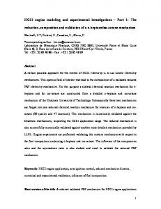
2. Operations Concept Given ground rules and assumptions, key processes were laid out for a fully reusable future launch vehicle concept. These are the same as those laid out for the deterministic model of the previous section with detail of depot maintenance now included. A logic model associated with the flow of ground processing was developed and figure 13 shows these engine flows by processing facility. The assumptions and ground rules are the same as in the deterministic case except for the following. Depot maintenance consists of engine removal and replacement, more detailed tests and checkout, and generally takes 30 days. Automated health monitoring is assumed, although this would only affect diagnostic and isolation time for unscheduled activities. Three vehicles may be on orbit at one time and two vehicles can be in depot maintenance at one time. The resources have been designed for minimal bottlenecks. This includes manpower, which is assumed available when and where needed, given shifting constraints. The block flows reflect periodic and depot maintenance operations that utilize parallelism and adequate manpower. For example, the engine processing for the three-engine vehicle is done in parallel. This provides a much shorter process clock time; however, manpower must be calculated accordingly. Typical engine operations include engine drying, inspection, and leak checks for the routine turnaround operations and engine removal and replacement for the depot maintenance operations. This discrete-event logic flow will be represented in a simulation model to be developed as part of this analysis. This flow will be modeled over a 20-yr lifetime. Results will be presented from a set of Monte Carlo runs. 3. Model Development A computer program that supports discrete-event simulation on a personal computer was used for this analysis. This package, Extend™, allows icon-based time and event modeling. The package is available commercially and provides ease of use in building models and in specifying output parameters. It supports probabilistic modeling and hierarchical levels of detail for complex systems. The logic of the operations processes timelines was incorporated into the Extend™ modeling language and runs were made to analyze the parameters of interest. All simulations for this analysis were performed on a PowerMac 7600. This operations model was developed fully from Extend™ library building blocks. Figure 15 presents the top level of the ground operations modeled. The model is reflected in a hierarchy, the lowest level of detail for the processing facility, as presented earlier in figure 13. From figure 15, the processing facility with five bays (three for nominal, two for depot); the two pads; the runway; and vehicle tows are evident. The five vehicles come in as scheduled in the new vehicle block to the appropriate routine processing in the upper three bays or the depot processing in the lower two bays. This probabilistic detailed model serves as an experience-based model outlined in the approach of figure 4 (lower half of schematic). Results from it are intended to be compared against the goal-oriented model results.
24
RPF New Vehicle
Transfer To Pad Nominal
To RPF
GoPad Depot
Mission LaunchA LaunchB
Runway Ops
Tow to Processing Facility
1
T
GoPad
count
Figure 15. Extend reusable engine operations model.
4. Data and Metrics for Analysis For this analysis, the data as described in section 5 were used for model data support. As stated earlier, this database keeps track of the ground operations unscheduled and scheduled maintenance activities for SSME processing. Distributions around the scheduled and unscheduled maintenance processing are modeled with a triangular distribution,22 selected due to its “conservative” nature. Evidence exists that for process simulation the lognormal distribution may be the most appropriate.23,24 Such evidence also exists relative to some aerospace applications;25,26 but without actual operational data to support this, the triangular distribution has been chosen. The triangular distribution requires a minimum, a maximum, and a mode. For this application the mode is the selected STS value, the minimum is 5 percent less than the mode, and the maximum 10 percent greater than the mode. These values were accepted during the data collection process by the system engineers as generally representative of actual shuttle engine task processing uncertainty. Extend™ supports many distribution types including the definition of a user input type. If desired, distribution types and parameters can be easily varied as part of a sensitivity study. Metrics for this analysis include measures of merit for availability and dependability. The measure of availability deemed most suitable for this analysis is the one described earlier in the metrics discussion for process availability—nominal processing divided by total processing which includes nominal and off-nominal processing times. Off-nominal processing time includes unscheduled maintenance, queuing delays, and standdown times due to failures. This is a measure deemed more suitable to spacecraft processing systems due to the processing-intensive nature of cryogenic-fueled rocket systems and small fleet sizes.
25
The dependability measure is a characterization of the on-time launches. This is reflected in a probability that all vehicles are launched on time (from an engine processing point of view), measured as within 2 days of original launch date. Requirements for engine processing were collected via the STS requirements list. There are three engines per vehicle with an engine out at liftoff capability. The only unique engine operation process proposed and not covered by STS operations is an engine-to-engine mate process which slightly expands the timelines for inspection and engine R&R. The reliability of the engine will be modeled as will any associated standdown time due to failures to illustrate the impact of reliability on operability. Standdown time in this case is 4 mo and is a required result of any vehicle failure. A range of reliability values and their impact to the overall processing system will be presented. Appendix E presents the engine out reliability analysis and its impact on engine set reliability that is used in this analysis. 5. Results The simulation time for the model was set to 20 yr and run in a Monte Carlo environment. A relatively evenly spaced flight manifest spanning this duration served as input for the model. Vehicle flights were staggered so that, at most, three flights were on orbit and, at most, two vehicles (engine sets) would require depot maintenance at any given time. It was apparent from back of the envelope analysis that the use of the complete shuttle engine database would present a processing timeline that was a factor of 10 over the allocated requirement. Availability for such a system is approximately 70 percent and dependability is very low unless processing start dates were backed up to allow for this extra processing. If enough time is allowed up front, any system can be made technically dependable. Implicit in the measure of dependability is an acceptable and minimal turnaround time. This is a problem in using the STS system. The inherent philosophy and conservatism associated with this manned system leads to intense processing requirements due to extensive checking and double-checking. Using shuttle experience data results in a vehicle that is only capable of five flights per year at the outset. The required processing times preclude any more. This also assumes processing manpower available to process all vehicles in parallel to support a maximum of 25 flights per year. This would result in a prohibitively expensive system. Thus, for this analysis, a decision was made to just use the “active” process conducted on the shuttle engines for this model. This excludes all vehicle setup and access time (except that explicitly allowed); all GSE setup; test setup; and of course, shuttle-specific operations. Clearly as important to the processing requirements for the future engine system is the philosophy of operation. Philosophy changes create the most significant process changes; of course, it remains to be seen whether these changes can be maintained when the actual system is in operation. Given the above ground rule, a baseline case with no off-nominal (unscheduled maintenance) time was first established. The results for the probabilistic analysis for the operability parameters are presented in table 5. This turnaround baseline required, on average, 109.6 hr per flight. When adjusting for manpower shifting, this translates into just over a 6-day turnaround. The dependability measure assumes launch on time if launch occurs within 2 days of the original scheduled data. This system is appropriately rated at 100 percent for both availability and dependability. Without unscheduled processing time, the only
26
uncertainty in this system is in normal processing and this is not enough to affect on-time launch. It is interesting to note that the original goal for the turnaround of the engine system as presented in the deterministic model was 40 hr. Even with extensive and optimistic ground rules, the projected turnaround is over twice that without considering any unscheduled processing. Extra manpower may make up some of the difference but this also raises the cost to the processing system. Clearly, the original goal must be adjusted to be more realistic. Table 5. Results of probabilistic analysis. Case
Availability (%)
Dependability (%)
Full-up STS Active Processes Only (No Unscheduled) Active With STS Unscheduled Active With 25% of STS Unscheduled
70
Low (Assumption Dependent)
100
100
82
0
94
78
When the shuttle-based, off-nominal times were incorporated into the model as reflected in table 5, the turnaround increased to an average of 171.5 hr which translates into a 12-day turnaround (a weekend added since processing facility time goes past 1 wk). With only 6 days allowed for turnaround time with a 2-day buffer, the dependability of this system is zero. Availability of this system is at 82 percent. It is reasonable to assume that improvements in unscheduled processing and hardware will result in something significantly better than for the shuttle. From table 5, the case where 25 percent of the shuttle unscheduled processing is assumed, the dependability is at 78 percent and the availability at 94 percent. Improvement to 10 percent of shuttle unscheduled processing improves the measures to 100 percent and 96 percent, respectively. The general relationships of process time, dependability, and availability for this system are presented in figure 16. A typical requirement (95 percent) for availability and dependability is also included in this figure. Availability varies from 100 to 82 percent, based upon the amount of unscheduled processing time. Dependability displays a unique shape—almost a step function. Only between 23 and 27 percent of STS unscheduled process time is any variation evident. This range is reflective of the variation in nominal and off-nominal processing. As such, dependability is a very sensitive measure. First, it is sensitive to the time allowed for processing—in this case, 6 days. Also, it is sensitive to the buffer amount; amount of uncertainty; and staffing schedules. Dependability can be improved by an early processing start or by the use of timing control mechanisms such as built-in holds. It is interesting to note that, traditionally, engine processing delays are not key to the vehicle launch delays and dependability. Weather is the predominant cause of vehicle launch delays. Other typical results from a discrete event simulation model include resource estimates of interest such as facility utilization rates, manpower usage, and queuing delays. In order to identify areas of improvement for operations, a Monte Carlo analysis of each process was performed by reducing the unscheduled maintenance from the shuttle-based percentage to a 10-percent target. Total manhours, cost per flow, and launch delay time per flight were used to provide a quantifiable measure of improvement. The results from these analyses are shown in table 7 for each engine task in the current processing flow.
27
Typical Requirement
100 90 80 70 60 % 50 40 30 20 10 0
Availability
Dependability
0
20
40
60
80
100
% STS Unsched Time
Figure 16. Operability measures by process time. 6. Effect of Uncertainty Table 6 presents the impact of the incorporation of uncertainty in the model. As discussed earlier, the purpose of modeling this uncertainty is to provide for a more realistic model. The hours presented are the total for the system over the 20-yr period (600 flights). The uncertainty in this case has little impact on the availability measure, given that availability is a ratio of values, both changing in similar fashion. In this case, the impact is small since the processes modeled have relatively low uncertainty in both scheduled and unscheduled activities. Also, consistent with earlier conclusions, the dependability measure shows a high sensitivity to the amount of uncertainty. Indeed the use of the maximum amount of uncertainty for the case here drops this value to zero. Upon further analysis, this was determined to be an effect of processing facility operation being extended past 5 days, resulting in the addition of a weekend to the processing time. These two events were enough to push the launch time past the 2-day buffer allowed. The dependability value is controllable to a large extent through the use of different ground rules, built-in holds, earlier start dates, or additional manpower. Table 6. Probabilistic model uncertainty impact. Case
Sched Hr
25% of STS Unscheduled Mode 25% — Min 25% — Max
166,460
Unsched Hr Avail (%) Dep (%) 11,482
93.5
78
162,348 171,552
10,764 12,402
93.8 93.2
95 0
7. Reliability Impacts When a measure of reliability is added to the model, impacts to operability are apparent. In this case, reliability is measured relative to catastrophic failure of the engine, and catastrophic failure of any engine leads to failure of the vehicle. The ground rule at the outset was that the system went into standdown of 4 mo after a failure in order to diagnose, isolate, redesign, or mitigate the problem causing the failure. The reliability impact of lost launches is presented in figure 17. Besides the failures, launches for the next
28
4 mo are delayed. Out of the 600 launches (rescheduled now over a longer period of time), 126 were canceled given an engine reliability of 0.95. For a reliability of 0.999, the number of lost launches is 1.8. Clearly, a reliability value much lower that 0.999 would be unacceptable to a launch system such as this one. Certain vehicle characteristics mitigate these failures (holddown, engine out), but the engines must be very robust for consistent acceptable operability scores. The relationship of reliability, dependability, and availability of this system as generated from the Extend™ model runs is presented in figure 18. The reliability estimates used for this analysis were as derived in the analysis of table 21 for the engine out at liftoff and catastrophic failure probability of 0.1 case. Clearly, reliability is the single biggest determinant of the operability of the system.
Average Missed Launches
140 120 100 80 60 40 20 0 0.95
0.97
0.99
0.999
Reliability
Figure 17. Impact of reliability on operability.
1.0 0.9
Availability
0.8
Percent
0.7 0.6
Dependability
0.5 0.4 0.3 0.2 0.1 0 0.94
0.96
0.98
1
Reliability
Figure 18. Operability metrics by reliability. These results indicate the impact of scheduled and unscheduled processing and reliability on the launch system. Values of acceptable availability and dependability requirements would likely be around 95 percent. Considerable improvements in traditional spacecraft engine processing and design are necessary to meet this requirement.
29
These results indicate a potential manhour cost savings of approximately $115.3K per flight along with a 7.4-hr reduction in the launch delay for the engine set modeled in this flow. The shuttle manpower data were used for this analysis. Figure 19 provides a graphical view of the manhour cost reductions and launch delay reductions for engine processing. While potential reductions are greatest in earlier processes (e.g., visual inspections), it is important to note that later processes may be more critical (e.g., pad activities). Timing controls such as built-in holds will be more effective earlier in the process flow. There is less opportunity for controlling delays late in launch.
Table 7. Engine processing manhours and launch delay reduction. Process MHRS (Sched)
Engine Drying Engine Access Visual Inspections Leak Checks Closeout Access Engine Purge Flight Readiness Test Launch Preparation
154 20 374 216 140 52 52 40
90 80
$K per Flow
70
Mhr Cost Reduction ($K)
Process MHRS (Total) 169 22 1,120 432 210 57 90 44
Process MHRS Cost3-Engine Set ($K)
Target Cost Reduction ($K)
Launch Delay Reduction (Hr)
20.2 2.6 134.4 51.8 25.2 6.8 10.8 5.3
1.7 0.2 80.7 23.4 7.6 0.2 1.4 0.1
0.03 0.05 1.6 2.4 1.2 0.8 0.5 0.8
2.5 Launch Delay Reduction (Hr)
2
60 1.5
50 40
1
30 20
0.5
10 0
Engine Engine Visual Leak Closeout Engine Flight Launch Drying Access Insp. Check Access Purge Read- Prep. iness Test Engine Operations
0
Figure 19. Engine operations manhours/cost analysis.
30
Hr per Flow
Process Description
By using the shuttle-based results and the process target results, a relationship between percent nominal processing and clock hours or manhour cost can be determined for each process analyzed. This type of relationship provides a means to estimate how much improvement is needed to reduce the manhour cost of a given process to a specified target value, and where the improvements are most needed.
31
7. CONCLUSIONS
Deterministic and probabilistic operations models of engine processing flows have been constructed to illustrate the methodology defined in this document. The goal was to select appropriate metrics, develop a model, and conduct an appropriate design operations analysis. This supports design trade studies where operations will be considered equally with performance analyses. Traditionally, this has been a serious shortcoming of disciplines such as design operations. It has not been understood how to conduct such an analysis and what measures of merit to use. This analysis presents such an approach and applies it to a future engine concept. These models support trade and sensitivity studies allowing users to investigate “what if” scenarios to support design decisions. With the availability and dependability measures, it provides a means to quantitatively analyze scheduled and unscheduled maintenance activities for operations analysis. The applications of this approach illustrate the traditional outcome in aerospace launch vehicle operations modeling. The difference between processing goals and initial historical-based operations estimates is large. This is at least in part due to the lack of good and accepted operations modeling techniques which use well-understood and interpretable metrics. The approach described here attempts to correct this problem by offering a rigorous process and good baseline data to identify operations concerns. The results presented here represent a first iteration in an operations analysis process outlined in figure 4 for a hypothetical engine concept. Deterministic, goal-oriented modeling provides a top view of the requirements and allocations. The bottom-up, probabilistic analysis provides the operations processing estimates to compare against the goals and requirements. The first iteration involved the use of the STS engine (SSME) experience base. Further iterations will adjust this baseline to better estimates based upon actual design decisions. All specifications of processing are subject to requirements traceability via the STS requirements database. Engine system scheduled and unscheduled maintenance impacts in the proposed launch vehicle flows have been identified. Critical path processes will have the greatest impact on launch delay. It is interesting to note that noncritical path processes defined in the initial operations concept may end up as critical path processes once an incidence of historical unscheduled maintenance activities is considered. From the results it is clear that the single biggest determinant of operability measures is reliability. While hardware reliability improvements are critical to improving operability, these results also point to improvements in corrective maintenance processing activities as critical to improved turnaround times and operability measures for future launch systems.
32
APPENDIX A—Engine Operations Requirements Database Table 8 presents SSME operations requirements (OMRSD’s) and other pertinent information to support definition and traceability for future engine requirements.
33
34
OMRSD NUMBER
E1 HYD - RETURN (JOINT H17) I/F LK CK
E1 GO2 ORB/SSME INTERFACE FLANGE LEAK CHECK SSME ENCAPSULATION POWER HD LEAK CK SSME ENCAPSULATION FUEL SYS ISO TEST SSME ENCAPSULATION OXID SYS ISO TEST SSME ENCAPSULATION HOT GAS SYS ISO TEST E1 GO2/GCV EXT LK CK & ORIFICE VERIF
E1 SENSOR CHECKOUT
E1 OPERATIONAL INSTRUMENTATION VERIFICATION E1 SENSOR IR VERIFICATIONS E1 HEX COIL LEAK TEST
V41AX0.020-I
V41AX0.050-A
V41AQ0.010-A
V41AU0.013-A
HEX EDDY CURRENT INSPECTIONS (TIME & CYCLE) HEAT EXCHANGER INSPECTION
HEX VISUAL INSPECTION
E1 HPFTP INTERNAL INSPECTION
HPFTP FIRST STAGE BLADE 22X INSPECTION HPFTP TURBINE INSPECTION (TIME & CYCLE)
V41BU0.086
V41BU0.115
V41BU0.125
V41BU0.075-A
V41BU0.079
HPFTP BELLOWS HEIGHT VERIF
E1 HPFTP TURBINE BEARING DRYING
V41BU0.087
V41CB0.050-A
V41BU0.080
SSME HEX COIL PROOF TEST
V41BP0.030
V41BU0.250-A V41BP0.020-A
V41BP0.010-A
V41BL0.034
V41BL0.033
V41BL0.032
V41BL0.031
E1 HYD - PRESS (JOINT H1) I/F LK CK
V41AX0.020-H
ER, PR, OMDP
E1 HELIUM (JOINT P1) I/F LK CK
E1 LH2 BLEED (JOINT F4.3) I/F LK CK
V41AX0.020-E
E1 GN2 (JOINT N1) I/F LK CK
E1 LO2 BLEED (JOINT O15) I/F LK CK
V41AX0.020-D
V41AX0.020-F
E1 GH2 PRESS (JOINT F9.3) I/F LK CK
V41AX0.020-C
V41AX0.020-G
ER, PR, OMDP
E1 LH2 FEED (JOINT F1) I/F LK CK
V41AX0.020-B
Component
System
EKSC
PLRU
PKSC
TC, DCE
PKSC
PLRU
TC
TC
PLRU
EKSC, LRU A, EKSC, PLRU
A, ER
EKSC, ER, LRU
HPFTP
HPFTP
HPFTP
HPFTP
HPFTP
HEX
HEX
HEX
HEX
Instrumentation HEX
Instrumentation
Instrumentation
Valves
F EKSC, I
System
System
Powerhead
Lines/Ducts
Lines/Ducts
Lines/Ducts
Lines/Ducts
Lines/Ducts
Lines/Ducts
Lines/Ducts
Lines/Ducts
Lines/Ducts
Lines/Ducts
HPOTP
HPOTP
F
F
EKSC & ER
A, ER
ER, PR, OMDP
ER, PR, OMDP
ER, PR, OMDP
ER, PR, OMDP
ER, PR, OMDP
ER, PR, OMDP
ER, PR, OMDP
E1 HPOTP PLUG WELD LEAK CHECK
E1 LO2 FEED (JOINT O1) I/F LK CK
V41BL0.060-A
PKSC, NRAT
OMRSD EFFECTIVITY PKSC, NRAT
OMRSD DESCRIPTION (V41 FILE III DATED 9/15/95)
SSME WELD 22 & 24 LEAK CHECK
V41AX0.020-A
V41BL0.050
V1011.01 Seq 03
V1011.02 Seq 08
V1011.02 Seq 11
V1011.04 Seq 03
V1011.02 Seq 07 V1011.04 Seq 02
V1011.06 Seq 02
V1011.04 Seq 07
V1011.05 Seq 12
V1011.05 Seq 05
V1011.05 Seq 07
V1011.05 Seq 09
V1011.05 Seq 05
V1011.05 Seq 07
V1011.05 Seq 09
V1011.05 Seq 07
OPF OMI's
V5E06 OSSU 2
V5E06 Seq 14
V5E06 Seq 14
V5E02 Seq 12
V5E02 Seq 14
V1294.003 Seq 04
V1294.003 Seq 03
V1294.002 Seq 06
V1294.002 Seq 17
V1294.007 Seq 04
V1294.007 Seq 04
V1294.007 Seq 04
V1294.007 Seq 04
V5E17 Seq 09
V5E17 Seq 09
V1294.004 Seq 04
V1294.007 Seq 04
ENGINE SHOP OMI's
V9018.002 Seq 04
V1046.005 Seq 07
V1046.005 Seq 06
V1046.001 Seq 04
V1046.001 Seq 04
V1046.005 Seq 05
V1046.005 Seq 05
V1149 Seq 15
V1046.001 Seq 05
V1046.002 Seq 04
V1046.003 Seq 05
V1046.004 Seq 04
V1046.002 Seq 04
V1046.003 Seq 05
V1046.004 Seq 04
V1046.003 Seq 07
VAB/PAD OMI's
V1038VL2 Seq 07
V1294.006 Seq 05
V5E18
V5E18
V1046.006 Seq 03
V1046.006 Seq 04
V1294.005 Seq 07
OTHER OMI's
V9001VL4 Seq 02
V9001VL4 Seq 02
V9002.06 Seq 05
V9002.06 Seq 05
RT OMI's
Table 8. Engine requirements database.
TURBOPUMPS
TURBOPUMPS
TURBOPUMPS
TURBOPUMPS
TURBOPUMPS
HEX
HEX
HEX
HEX
HEX
AVIONICS
AVIONICS
ENGINE
ENGINE
ENGINE
ENGINE
DUCTS
DUCTS
DUCTS
DUCTS
DUCTS
DUCTS
DUCTS
DUCTS
DUCTS
DUCTS
SUBSYSTEM CODE
OMRSD RATIONALE/ROOT CAUSES
Verify no inlet or discharge sheet metal cracking; no nozzle cracking or erosion; no blade cracking, platform cracking, or erosion; no fishmouth seal cracking or missing pieces; no bellows shield cracking. (All inspections completed with tVerify rbopnomp ins cracking due to previous occurrences of airfoil blade cracking Verify no inlet or discharge sheet metal cracking including weld 450 and the turning vanes; no nozzle cracking or erosion; no blade cracking, platform cracking, or erosion; no fishmouth seal cracking or missing pieces; no bellows shield cracking via dVerify bellows height adequate to provide proper preload on the bellows at installation. Incorporated as a result of a previous failure of the bellows. Ensure all moisture is removed from the bearing area after a test/flight
Functional check of each turbine discharge temp Mat.'l (stringer) or Weld Thru-Crack; HPOTP Installation Impact Hole -> HG to Tank; Crit. 1 Mat.'l (stringer) or Weld Thru-Crack; HPOTP Installation Impact Hole -> HG to Tank; Crit. 1 Thin Walls from Bracket Wear, Manuf -> Thru-Crack, HG Leakage to Tank, Crit. 1 Visible Impact Damage, Bracket Wear -> Thru-Crack -> HG to Tank, Crit 1; Turn. Vane Cracks -> Loss of Vane Impact MI Post -> Damage or Crit 1. HPOTP Installation Impact Hole -> HG to Tank; Crit. 1
Instrumentation integrity checkout
System leak Integrity check for launch - Mat.'l or Weld ThruCrack; Seal not Seated -> Crit. 1 System leak Integrity check for launch - Mat.'l or Weld ThruCrack; Seal not Seated -> Crit. 1 System leak Integrity check for launch - Mat.'l or Weld ThruCrack; Seal not Seated -> Crit. 1 System leak Integrity check for launch - Mat.'l or Weld ThruCrack; Seal not Seated -> Crit. 1 Establishes leak test of all gaseous oxygen system joints from the AFV to the orbiter interface on an each flight basis. Planned Preflight Checkout
Joint Integrity Post Engine Installation
Joint Integrity Post Engine Installation
Joint Integrity Post Engine Installation
Joint Integrity Post Engine Installation
Joint Integrity Post Engine Installation
Joint Integrity Post Engine Installation
Joint Integrity Post Engine Installation
Joint Integrity Post Engine Installation
Due to poor processing, HPOTP balance cavity standoff welds are leak checked -- No leaks ever verified, but lack of weld penetration up to 90% has been found on these welds. Standoffs have been suspected of leaking and caused return to Canoga Plug weld leak occurred on a unit -- Concern over these welds leaking either Gox/Helium/Hot gas into boattail -- therefore all external plug welds on the housing are checked Ensure joint integrity of LPOTP to pump inlet ducting after engine is installed Verify pump inlet joint integrity after installing the LPFTP
Root Cause Categories
Fire, Uncontained engine failure
Fire, Uncontained engine failure
Fire, Uncontained engine failure
Fire, Uncontained engine failure
Fire, Uncontained engine failure
Fire, Uncontained engine failure
Fire, Uncontained engine failure
Fire, Uncontained engine failure
Fire, Uncontained engine failure
Erroneous shutdown, loss of vehicle Fire, Uncontained engine failure
Erroneous shutdown, loss of vehicle
Erroneous shutdown, loss of vehicle
Aft Compartment overpressurization or fire
Aft Compartment overpressurization or fire
Aft Compartment overpressurization or fire
Aft Compartment overpressurization or fire
Aft Compartment overpressurization or fire
Aft Compartment overpressurization or fire
Aft Compartment overpressurization or fire
Aft Compartment overpressurization or fire
Aft Compartment overpressurization or fire
Aft Compartment overpressurization or fire
Aft Compartment overpressurization or fire
Aft Compartment overpressurization or fire
Aft Compartment overpressurization or fire
Aft Compartment overpressurization or fire
Aft Compartment overpressurization or fire
Aft Compartment overpressurization or fire
Aft Compartment overpressurization or fire
35
A, RI, PSI, ER, PLRU
F
E1 ATD BLOCK I/II HPOTP INTERNAL INSPECTION
E1 LPFTP TORQUE TEST HPOTP/AT PBP TIEBOLT LOCK HPOTP/AT CONTAMINATION INSPECTION SSME HPOTP/AT TURBINE BEARING DRYING LPFTP INVESTIGATIVE TORQUE
E1 LPOTP TORQUE TEST
LPOTP INVESTIGATIVE TORQUE
V41BU0.065-A
V41BS0.010-A V41BU0.127 V41BU0.128 V41CB0.085
V41BS0.030-A
V41BU0.082-B
OXID P/B INJECTOR ELEMENT INSP
PLRU
DCE DCE
FPB INJECTOR OXID POSTS INSP
FPB DIFFUSER INSPECTION
V41BU0.105
V41BU0.570
Powerhead
Valves
TC A, GP F EKSC, LRU F EKSC, LRU
RIV OVERRIDE SEALS LEAK TEST (TIME & CYCLE) AFV SEAT AND SHAFT SEAL LEAKAGE AFV SHAFT AND SEAT ISOLATION E1 PROP VALVE ACT PNEU SEAL LEAK PROP VALVE ACT PNEU SEAL ISO TEST E1 AFV CRACKING PRESSURE TEST
V41BQ0.080
V41BQ0.100 V41BQ0.101 V41BQ0.170-A V41BQ0.171 V41BR0.030-A
System
EKSC
E1 ENVIR CLOSURE INSTALLATION
V41CB0.020-A
Preburner
Valves Valves Valves Valves Valves
System
OPB FACEPLATE FLATNESS CHECKS
E1 COMPONENTS INTERNAL INSPECTION EKSC
V41BU0.032
Preburner
Preburner
Preburner
Preburner
Preburner
Preburner
Preburner
Preburner
V41BU0.040-A
TC
SSME FUEL P/B INJECTOR ELEMENT INSP. MSP (IF ONE OR MORE PINS FOUND MISSING)
TC, MSP
PLRU
PLRU
PLRU
PLRU
V41BU0.088
OPB LINER INSPECTION
OXIDIZER PREBURNER INSPECTION
V41BU0.082-D
V41BU0.085
FPB LINER INSPECTION
V41BU0.082-C
V41BU0.081-D
V41BU0.081-C
OXIDIZER SIDE TRANSFER TUBE INSPECTION FUEL PREBURNER INSPECTION
V41BU0.081-B
Powerhead
Nozzle
NOZZLE PARENT METAL DISCOLORATION EKSC INSPECTION
FUEL SIDE TRANSFER TUBE INSPECTION
V41BU0.353-E PLRU
Nozzle
MCC/Nozzle Nozzle
EKSC
V41BU0.353-D
EKSC, LRU, I F
E1 MCC TO NOZZLE SEAL LEAK TEST SSME NOZZLE ENCAPSULATION LEAK TEST NOZZLE VISUAL INSPECTION
MCC/Nozzle
MCC
PLRU EKSC
MCC
MCC
PLRU
EKSC
MCC
MCC
Main Injector
LPOTP Main Injector
LPOTP
LPOTP
LPFTP
LPFTP HPOTP HPOTP HPOTP
HPOTP
HPOTP HPOTP Lines/Ducts
Lines/Ducts
EKSC, LRU
F
EKSC
A, ER, PLRU DLP
F
A, RI, PSI, ER, PLRU F A, PKSC PKSC
PKSC, NRAT
EKSC, RI, PLRU F DCE
Component Lines/Ducts
V41BQ0.200-A V41BQ0.167
V41BQ0.160-A
V41BU0.082-A
V41BU0.081-A
V41BU0.031-A
E1 MCC BONDLINE ULTRASONIC INSPECTION MCC INJECTOR INSPECTION WITH HPFTP REMOVED MCC INJECTOR INSPECTION WITH HPOTP REMOVED E1 THRUST CHAMBER NOZZLE LEAK TEST
V41BQ0.165
E1 MCC LINER CAVITY DECAY CHECK
E1 MAIN INJECTOR LOX POST BIASING
MCC ISOLATION LEAK TEST
V41BU0.034-A
V41BQ0.240-A
E1 LPOTP SHAFT TRAVEL E1 MAIN INJECTOR LOX POST VACUUM DECAY
V41BS0.032-A V41BR0.040-A
V41BS0.031
V41BS0.011
HPOTP/AT TORQUE TEST HPOTP/AT INVESTIGATIVE TORQUE SSME LPFD TRIPOD LEGS INSPECTION
F
V41BS0.050 V41BS0.055 V41BU0.405
OMRSD EFFECTIVITY
PERFORM LPFD XRAY INSPECTION
F
V41BU0.400
OMRSD DESCRIPTION (V41 FILE III DATED 9/15/95)
E1 LPFD OVALITY CHECK
OMRSD NUMBER
V41BU0.390-A
V1011.04 Seq 07 V1011.04 Seq 07 V1011.05 Seq 12 TBD V1011.04 Seq 07
TBD
S0028 Seq 19
V1011.02 Seq 08
TBD
TBD
V1011.02 Seq 05
V1011.02 Seq 05
V1011.05 Seq 08
V1011.05 Seq 09
V1011.02 Seq 05
V1011.02 Seq 04
V1011.03 Seq 05 V1011.02 Seq 08
V1011.03 Seq 05
V1011.03 Seq 05
V1011.03 Seq 04
V1011.03 Seq 04 V1011.03 V1011.0? Seq ?? V1011.01 Seq 03
V1011.02 Seq 08
V1011.03 Seq 06 V1011.03 Seq 06 TBD
TBD
V1011.02 Seq 10
OPF OMI's
V1046.005 Seq 05
V1294.002 Seq 10 V1294.002 Seq 17
V1046.004 Seq 08
V1046.004 Seq 04
V9018.002 Seq 04
VAB/PAD OMI's
V1046.005 Seq 05 V1046.005 Seq 05 V1046.006 Seq 04
V5E06 Seq 12
V5E02 Seq 14
V5E02 Seq 14
V5E02 Seq 14
V5E06 Seq 12
V5E02 Seq 14 V5E06 Seq 12
V5E06 Seq 12
V1294.004 Seq 03 V1294.010 Seq 03
V1294.011 Seq 06
V5E02 Seq 14
V5E06 Seq 12
V1294.003 Seq 05
V1294.003 Seq 06
V5E23
V5E23
V1294.008 Seq 04
V5E02 Seq 25 V5E02 Seq 25
ENGINE SHOP OMI's
V1011.06 Seq 03
S0026
V1038VL2 Seq 08
V1038VL2 Seq 08
V1038VL2 Seq 08
V1038VL2 Seq 08
V9018.002 Seq 10
OTHER OMI's
V5E17 Seq 09
RT OMI's
COMBUSTION
COMBUSTION
COMBUSTION
COMBUSTION
COMBUSTION
COMBUSTION
COMBUSTION
COMBUSTION
COMBUSTION
COMBUSTION
COMBUSTION
COMBUSTION
COMBUSTION
COMBUSTION
COMBUSTION COMBUSTION
COMBUSTION
COMBUSTION
COMBUSTION
COMBUSTION
COMBUSTION
COMBUSTION
TURBOPUMPS COMBUSTION
TURBOPUMPS
TURBOPUMPS
TURBOPUMPS
TURBOPUMPS TURBOPUMPS TURBOPUMPS TURBOPUMPS
TURBOPUMPS
TURBOPUMPS TURBOPUMPS DUCTS
DUCTS
SUBSYSTEM CODE
DUCTS
Table 8. Engine requirements database (Continued). OMRSD RATIONALE/ROOT CAUSES
Root Cause Categories
Fire, Uncontained engine failure
Damaged Posts Pinned, Loss of Pins -> Increase Damage to Post -> Loss of Post into Turbine, Crit. 1 or Internal Leakage -> Overheat Turbine, Crit. 1 Damaged Posts Pinned, Loss of Pins -> Increase Damage to Post -> Plug Post & Use or Loss of Post into Turbine, Crit. 1 or Internal Leakage Overheat Turbine, Crit. 1 Damaged Posts Pinned, Loss of Pins -> Increase Damage to Post -> Plug Post & Use or Loss of Post into Turbine, Crit. 1 or Internal Leakage Overheat Turbine, Crit. 1 Contingency reqmt performed to inspect for cracks in FPB diffuser. This reqmt will be invoked only if data evaluation of HPFTP turbine discharge temp deems it necessary Integrity check after "POP" - "POP" Damage , Bowing Indication of Braze Cracks -> Loss of Element into Turbine, Crit 1; of Internal Leakage -> Overheat Turbine, Crit. 1 Boroscope inspection of accessible engine areas without disassembly Insure that LPFD helium barrier system is functional to preclude cryopumping in the event of a launch scrub which can lead to a collapse of the duct. Periodic (every 10 starts). To verify that the RIV shaft seals maitain override opening pressure within the RIV. No LOX in HEX prestart - Crit 1 Isolation check if the V41BQ0.100 leakage limits are exceeded Valve/Seal Leakage - LRU Integrity Check Isolation check if the V41BQ0.170-A leakage limits are Verify proper AFV operation - Crit 1
Inspect when HPOTP Removed
Inspect when HPOTP Removed
Inspect when HPFTP Removed
Inspect when HPFTP Removed
Inspect when HPOTP Removed
Fire, Uncontained engine failure
Fire, Uncontained engine failure Fire, Uncontained engine failure Fire, Uncontained engine failure Fire, Uncontained engine failure Fire, Uncontained engine failure
Fire, Uncontained engine failure
Fire, Uncontained engine failure
Fire, Uncontained engine failure
Fire, Uncontained engine failure
Fire, Uncontained engine failure
Fire, Uncontained engine failure
Fire, Uncontained engine failure
Fire, Uncontained engine failure
Fire, Uncontained engine failure
Fire, Uncontained engine failure
Fire, Uncontained engine failure
Fire, Uncontained engine failure
Fire, Uncontained engine failure
Fire, Uncontained engine failure
Fire, Uncontained engine failure
Fire, Uncontained engine failure Fire, Uncontained engine failure
Fire, Uncontained engine failure Fire, Uncontained engine failure
Inspect when HPOTP Removed
Fire, Uncontained engine failure
Fire, Uncontained engine failure
Fire, Uncontained engine failure
Fire, Uncontained engine failure
Fire, Uncontained engine failure Fire, Uncontained engine failure
Fire, Uncontained engine failure
Fire, Uncontained engine failure
Fire, Uncontained engine failure
Fire, Uncontained engine failure Fire, Uncontained engine failure Fire, Uncontained engine failure Fire, Uncontained engine failure
Fire, Uncontained engine failure Fire, Uncontained engine failure Fire, Uncontained engine failure
Fire, Uncontained engine failure
Fire, Uncontained engine failure
Cold or Hot Wall Thru-Crack; Degraded Liner Mat.'l or Bebond > Repair; UAI Performance Loss; Crit 3 to Crit 1 if increase. If no action required then data used to adjust engine performance predictions G-15 Seal Thermal Degradation -> Aft Compartment Leak, Crit. Cold or Hot Wall Thru-Crack like Crown Erosion, Brazeless Tube Ends -> Repair; UAI Performance Loss; Crit 3 to Crit 1 if Erosed Tube Crowns -> Leakage up to Crit 1; Tube Bulges -> Trip HG Flow or Shock Wave -> Dyn. Destruction NZ, Crit 1; Reentry Annealing -> Mat.'l Degradation, Burst -> Crit. 1 Erosed Tube Crowns -> Leakage up to Crit 1; Tube Bulges -> Trip HG Flow or Shock Wave -> Dyn. Destruction NZ, Crit 1; Reentry Annealing -> Mat.'l Degradation, Burst -> Crit. 1 Inspect when HPFTP Removed
Internal Debonds -> Emplosion, Crit 1; External Leak, UAI to Crit 1 Inspect when HPFTP Removed
Verify all moisture is removed from the bearing area after a test/flight. Investigative torque check if the specification limits are exceeded - torque check failure generally lift-off seal binding or laby seal - copper plating rub Done to ensure rotor is not bound up prior to start -- concern over contamination if high and also start characteristics if rotor is slow to spin -- contamination has been found that bound the rotor and bearing wind-up can also routinely causes failure of Performed to free the rotor if possible - done only if needed -must make torque return to normal value or pump is removed Bearing wear on LPOTP thrust bearing must be monitored LOX Post integrity check - Impacted or Defected Post Plugged & Plug Damaged -> Loss of Plug, Increase Damage to Post -> Loss of Post, Crit. 1 Under Bias (cant) -> Flow Erosion MCC H/G Wall -> Repair or Crit. 1 Leak; Under Bias -> Combustion Performance Loss Mat.'l Debond @ Liner Aft -> Repair; UAI Performance Loss; Crit 3 to Crit 1 if increase. Burst Diaphragm Damage, Internal Liner To Structure Thru-
Contingency test performed only when the LPFD helium barrier system has been damaged. Object is to detect potential duct collapse or separation from the layer of insulation by measuring the roundness of the duct. Contingency reqmt preformed only when the ovality check indicates that some damage or collapse has occurred in the LPFD. The cross section is X-rayed in an attempt to verify Replaced by V41BS0.040-A Replaced by V41BS0.042 Performed to insure LPFD structural integrity. Inspection is performed if post flight data evaluation reveals HPFTP unacceptable synchronous frequencies. No HPOTP/AT internal inspections were made during certification. Inspections of the turbine, mainstage pump and PBP inlets, and all three bearings have been added only because the inspections aren't time consuming and because Verify rotor is free to rotate prior to testing
36
OMRSD DESCRIPTION (V41 FILE III DATED 9/15/95)
E3 COMPONENTS EXTERNAL INSPECTION EKSC
F
E2 HPOTP IMPELLER LOCK VERIF E3 HPOTP IMPELLER LOCK VERIF SSME HOT GAS SYS SEAL LK ISO TEST E1 SSME COMB HOT GAS TO FUEL SYS REV LK CK
SSME HOT GAS REVERSE ISO LK CK F E1 FUEL BLEED VALVE SEAT LEAK TEST EKSC, LRU E2 COMPONENTS EXTERNAL INSPECTION EKSC
LRU A, RI, PLRU
FUEL TP PIST/NAFLEX/MFV ISO TEST E1 COMB HOT GAS SYS SEAL LEAK TEST
FUEL BLEED VALVE BELLOWS LEAK TEST E2 MCC BONDLINE ULTRASONIC INSPECTION E3 MCC BONDLINE ULTRASONIC INSPECTION OXID BLEED VALVE BELLOWS LEAK TEST E1 HPFTP TORQUE TEST
HPFTP INVESTIGATIVE TORQUE
E1 GIMBAL ELECTRICAL BONDING TEST
E1 ELECTRICAL INTERFACE PANEL BONDING TEST
E1 SSME/TVC ELECTRICAL BONDING TEST
E1 SSME CONTROLLER POWER APPLICATION
E1 AC POWER REDUNDANCY VERIFICATION E1 CONTROLLER POWER SUPPLY REDUNDANCY VERIF
V41BQ0.021 V41BQ0.050-A
V41BS0.043-B V41BS0.043-C V41BQ0.051 V41BQ0.052-A
V41BQ0.053 V41BQ0.030-A V41BU0.030-B
V41BU0.030-C
V41BQ0.032 V41BU0.031-B
V41BS0.021
V41AL0.010-A
V41AL0.020-A
V41AL0.030-A
V41AN0.010-A
V41AN0.020-A
EIU 1 READINESS TEST
E1 GIMBAL BEARING SENSOR CHANNELIZATION VERIF E1 POST-FLT STRAIN GAGE CHECKOUT
V41AN0.035-A
V72AQ0.020-A
V41AU0.060-A
Valves
Powerhead
HGM OXID SIDE DYE PEN INSP (PHASE II)
TC HGM FUEL SIDE DYE PEN INSP (PHASE II+) HGM OXID SIDE DYE PEN INSP (PHASE II+) TC
V41BU0.351-A
V41BU0.352-A
V41BU0.093
V41BU0.096
V41BU0.097
V72AQ0.040-A
V41BU0.098
VERIFY SSME 1/EIU 1 COMMAND PATH
Powerhead
E1 PRELAUNCH MCC LINER POLISHING
HGM FUEL SIDE DYE PEN INSP (PHASE II) TC TC
E1 MFVA PRI HEATER POWER ON COMMAND E1 MFVA SEC HEATER POWER ON COMMAND E1 POST FLIGHT MCC LINER POLISHING
V41AP0.020-D
A, LRU
A
EKSC
I
I
A, PLRU, I, NRAT
ER, LRU
Avionics
Powerhead
Powerhead
MCC
MCC
Valves
Valves
Instrumentation
Instrumentation
Instrumentation
Instrumentaiton
V41AP0.020-A
V41AU0.042-A
V41AU0.020-A
A, EKSC A, ER
E1 POST-FLIGHT SENSOR CHECKOUT
E1 MADS INSTRUMENTATION VERIFICATION E1 SKIN TEMP CHANNELIZATION VERIFICATION E1 HPOTP STRAIN GAGE DEBOND TEST
Instrumentaiton
Instrumentaiton
V41AU0.016-A
A, EKSC
ER, LRU
Avionics
Avionics
LRU A, LRU
Avionics
Avionics
Avionics
Avionics
Avionics
Avionics
Avionics
Avionics
HPFTP
Valves HPFTP
Valves
System Valves
System System
HPFTP, LPFTP, MFV System
HPFTP, LPFTP, MFV HPFTP, LPFTP, MFV
HPFTP, LPFTP, MFV
A, ER, LRU
LRU
A, LRU
A, ER
A, ER
A, I, ER
I, ER
I, ER
EKSC
LRU EKSC
PKSC, PLRU, NRAT PKSC, PLRU, NRAT F PKSC
F EKSC, LRU
Component Valves
V41AU0.090-D
V41AU0.090-A
V41ZA0.010
E1 CONTROLLER 28V MEMORY TEST
E1 COMMANDED CONTROLLER CHECKOUT SSME HARNESS REPLACEMENT RETEST
V41AN0.023-A
V41AN0.022-A
V41BQ0.034 V41BS0.020-A
V41BU0.031-C
FUEL TP L/O/MFV SEALS ISOLATION TEST F E1 FUEL TP PIST/NAFLEX/MFV LK CK EKSC
V41BQ0.011 V41BQ0.020-A
A EKSC, ER
AFV FILTER REPLACEMENT
E1 FUEL TP L/O/MFV BALL SEAL LK TEST
OMRSD EFFECTIVITY
V41BQ0.010-A
A
V41BU0.220-D
AFV FILTER INSPECTIONS
OMRSD NUMBER
V41BU0.220-A
V1011.02 Seq 05
V1011.06 Seq 08
V1011.02 Seq 04
V1011.06 Seq 02
V1011.06 Seq 02
V1011.03 Seq 09
V1011.05 Seq 11 V1011.03 Seq 09
V1011.02 Seq 05
V1011.05 Seq 10 V1011.02 Seq 05
V1011.02 Seq 04
TBD V1011.05 Seq 04 V1011.02 Seq 04
V1011.03 Seq 06 V1011.03 Seq 06 TBD V1011.05 Seq 09
V1011.05 Seq 05 V1011.05 Seq 09
TBD V1011.05 Seq 05
V1011.05 Seq 05
V1011.04 Seq 07
V1011.04 POSU 5
OPF OMI's
V5E02 Seq 14
V5E06 Seq 12
V5E02 Seq 14
V5E06 Seq 12
V5E02 Seq 27 & V1294.002
V1294.002 POSU 11
V5E02 Seq 27
V1294.002 Seq 07
V1294.002 Seq 03
V1294.002 Seq 08
V5E06 OSSU 1
V1294.006 Seq 03 V5E06 OSSU 1
V1294.005 Seq 03
V1294.005 Seq 03
V1294.005 Seq 06
V5E02 Seq 25 V5E02 Seq 25
V1294.005 Seq 03 V1294.005 Seq 06
V1294.005 Seq 03
V1294.007 Seq 03
ENGINE SHOP OMI's
V1294.002 POSU 6
S1287 OSSU 9
V1046.001 Seq 13
V1046.001 Seq 13
V1046.001 Seq 12
V1046.001 Seq 04
V1046.001 Seq 04
V1046.001 Seq 04
S1287 OSSU 3
V1046.003 Seq 09
V1046.002 Seq 07
V1046.002 Seq 05
V1046.004 Seq 04
V1046.002 Seq 06 V1046.004 Seq 04
V1046.002 Seq 06
V1046.002 Seq 03
V1046.005 Seq 05
V1046.005 POSU 2
VAB/PAD OMI's
V9001VL4 Seq 02
V1038VL2 Seq 08
V9001VL4 Seq 02
V5005 Seq 06
V5005 Seq 06
V1038VL2 Seq 08
V1038VL2 Seq 08
V5005 POSU 3
OTHER OMI's
V9001VL4 Seq 02
V9001VL4 Seq 02
V9001VL4 Seq 02
V9001VL4 Seq 09
V9001VL4 Seq 09
V9001VL4 Seq 02
V9001VL4 Seq 02
V5087 Task 28
RT OMI's
AVIONICS
COMBUSTION
COMBUSTION
COMBUSTION
COMBUSTION
COMBUSTION
COMBUSTION
AVIONICS
AVIONICS
AVIONICS
AVIONICS
AVIONICS
AVIONICS
AVIONICS
AVIONICS
AVIONICS
AVIONICS
AVIONICS
AVIONICS
AVIONICS
AVIONICS
AVIONICS
AVIONICS
AVIONICS
AVIONICS
TURBOPUMPS
TURBOPUMPS
COMBUSTION
COMBUSTION
TURBOPUMPS TURBOPUMPS
SUBSYSTEM CODE
Table 8. Engine requirements database (Continued). OMRSD RATIONALE/ROOT CAUSES
Remove Liner Roughness from Intense Environ. -> Erosion -> Leakage, Performance Loss Remove Surface Oxiditation -> Erosion -> Leakage, Performance Loss Liner Mat.'l & Transfer Tube Weld Thru-Cracks -> By-pass Flow Performance Loss Liner Mat.'l & Transfer Tube Weld Thru-Cracks -> By-pass Flow Performance Loss Liner Mat.'l & Transfer Tube Weld Thru-Cracks -> By-pass Flow Performance Loss Liner Mat.'l & Transfer Tube Weld Thru-Cracks -> By-pass Flow Performance Loss
Changeout Verification
Weld #3 Strain gage in place to detect uneven bearing wear -debond test needed to ensure acceptable data on next flight Changeout Verification
Instrumentation integrity checkout
Instrumentation integrity checkout
Part of this check is Weld #3 Strain Gage checkout -- needed to ensure electrical continuity of gage after bond is assured Instrumentation integrity checkout
Instrumentation integrity checkout
Investigative torque check if the specification limits are exceeded Verifies proper electrical grounding conditions exist between the SSME gimbal bearing and the orbiter structure. Test performed each time the bonding straps are disturbed. Verifies proper electrical grounding conditions exist between the SSME electrical interface panel and the orbiter structure. Test performed each time the bonding straps are disturbed. Verifies proper electrical grounding conditions exist between the SSME TVC actuator attach points and the orbiter structure. Test performed each time the bonding straps are disturbed. Defines the proper sequencing of cockpit switches for application of SSME controller power as well as the values of the monitored responses. Identifies the constraints for cooling air and FACOS power. Provides for SSME AC power redundancy verification while controllers are under power load. Performs a redundancy verification of the SSME controller power supplies. Controller channels A&C and B&C are verified. This procedure also verifies the backup memory power is functional and verifies the AC supplied +10 V Verifies the capability of the 28 volt DC and battery systems are holding up the controller memory. Controller Changeout Verification. Functional hardware and software checkout. Defines the continuity and insulation resistance tests to be performed on any replacement harness installed on an engine
Isolation check if the V41BQ0.050-A leakage limits are Verify no reverse LPFTP or HPFTP carbon nose leakage (Hot gas system pressurized, measure leakage into fuel system) Incorporated when the pump end to turbine end leak check did not detect existing carbon nose leakage. Isolation check if the V41BQ0.052-A leakage limits are Valve Leakage Check Handling Damage, Clearence Checks, Loose Spot Welds on or Melted TPS Handling Damage, Clearence Checks, Loose Spot Welds on or Melted TPS LRU - Remove and replace verification Internal Debonds -> Emplosion, Crit 1; External Leak, UAI to Crit 1 Internal Debonds -> Emplosion, Crit 1; External Leak, UAI to Crit 1 LRU - Remove and replace verification Verify the rotor is free to rotate prior to testing
Contamination check to verify that filter is not plugged which could lead to a collapse of the HEX. Contamination check to verify that filter is not plugged which could lead to a collapse of the HEX. Verify no LPFTP or HPFTP lift-off seal carbon nose leakage or main fuel valve ball seal leakage. (Fuel system pressurized, measure leakage into hot gas system) Isolation check if the V41BQ0.010-A leakage limits are Verify no LPFTP or HPFTP large diameter secondary seal leakage or Naflex or MFV leakage (Fuel system pressurized, measure leakage out of the fuel component drain) Isolation check if the V41BQ0.020-A leakage limits are Verify no LPFTP or HPFTP small diameter secondary seal leakage or other system leakages (Hot gas system pressurized, measure leakage out of the fuel component drain)
Root Cause Categories
Unscheduled Maintenance Action or Launch Delay Unscheduled Maintenance Action or Launch Delay Unscheduled Maintenance Action or Launch Delay Unscheduled Maintenance Action or Launch Delay Unscheduled Maintenance Action or Launch Delay Unscheduled Maintenance Action or Launch Delay Unscheduled Maintenance Action or Launch Delay Unscheduled Maintenance Action or Launch Delay Unscheduled Maintenance Action or Launch Delay Unscheduled Maintenance Action or Launch Delay Unscheduled Maintenance Action or Launch Delay Unscheduled Maintenance Action or Launch Delay Unscheduled Maintenance Action or Performance loss Unscheduled Maintenance Action or Performance loss Unscheduled Maintenance Action or Performance loss Unscheduled Maintenance Action or Performance loss Unscheduled Maintenance Action or Performance loss Unscheduled Maintenance Action or Performance loss
Unscheduled Maintenance Action or Launch Delay Unscheduled Maintenance Action or Launch Delay
Unscheduled Maintenance Action or Launch Delay
Unscheduled Maintenance Action or Launch Delay
Unscheduled Maintenance Action or Launch Delay
Hazardous gas buildup Improper start, Ox rich resulting in engne fire Improper start, Ox rich resulting in engne fire Unscheduled Maintenance Action or Launch Delay
Hazardous gas buildup
Hazardous gas buildup Hazardous gas buildup
Hazardous gas buildup Hazardous gas buildup
Hazardous gas buildup Hazardous gas buildup
Hazardous gas buildup Hazardous gas buildup
Hazardous gas buildup
Fire, Uncontained engine failure
Fire, Uncontained engine failure
37
OMRSD NUMBER
DRYNESS VERIFICATION (PHASE II)
E1 FRT CHECKOUT
V41CB0.081
V41AS0.030-A
V41BU0.070-A
V41BQ0.191
V41BQ0.120-A V41BQ0.121 V41BQ0.130 V41BQ0.140-A V41BQ0.141-A V41BQ0.150-A V41BQ0.180 V41BQ0.190
V41BQ0.041
V41BQ0.040-A
V41BU0.130-A V41BU0.130-B V41AS0.010-A
V41AS0.030-D
E1 AFT CLOSEOUT INSPECTION
FPOV SLEEVE TEST & WINDOW CALIB
E1 OXIDIZER PROP VLVS/PRG C/V LEAK TEST OXIDIZER PROP VLVS/PRG C/V ISOLATION TEST E1 LO2 PROP VALVE BALL SEAL LEAK LO2 PROP VALVE BALL LKG ISOLATION RIV SHAFT SEAL LEAK TEST (TIME & E1 RIV SEAT FLOW TEST E1 OBV SEAT LEAK TEST E1 GCV CHECK VALVE LEAK TEST HPV CHECK VALVE LEAK TEST OPOV SLEEVE TEST & WINDOW CALIB
E1 FRT PNEUMATIC SHUTDOWN SEQ DATA VERIF E1 YAW MPS TVCA ALIGNMENT E1 PITCH MPS TVCA ALIGNMENT E1 ACTUATOR CHECKOUT
ENGINE DRYING - 2ND PURGE (PHASE II)
V41CB0.080-E
V41CB0.030 V41CB0.080-D
E1 HE BARRIER SYS INSPECTION POST FLIGHT FERRY FLIGHT SET INSTALLATION ENGINE DRYING - 1ST PURGE (PHASE II )
OPENING CLOSEOUT COVERS SSME POSITIONING POST LANDING
V41BW0.050 V41CB0.010
V41CB0.012-A
INSTL SSME STORAGE/SHIPPING COVERS ERS
V41BW0.034
A
I, LRU Valves
Valves
Valves Valves Valves Valves Valves Valves Valves Valves Valves
Valves
F EKSC, ER F TC EKSC EKSC, LRU EKSC, LRU TC I, LRU
EKSC, I
Systems
TVC TVC Valves
EKSC, ER, LRU
Systems
System
System
System System
System
System System
System
System System System
LRU, 1ST LRU, 1ST EKSC, ER, LRU
EKSC, ER, LRU
EKSC
EKSC
FF EKSC
EKSC
ENV PLCL
ER, MOD, LRU A A
V41BU0.520-A V41BU0.530-A V41BW0.031-A
System
System
V1011.05 Seq 07 TBD TBD V1011.05 Seq 06 V1011.05 Seq 06 V1011.04 Seq 06 TBD
V1011.05 Seq 09
TBD TBD V1011.06 Seq 05
V1011.06 Seq 08
V1011.06 Seq 06
V1263 Seq 04
V5057
V5057
V1063 Seq 14 V41-50024 V41-20003
V1063 Seq 14
V1011.02 Seq 04
System
ER, MOD, LRU
EKSC
A, LRU
FUEL SYSTEM LAI INSPECTION
E1 HELIUM BARRIER SYS INSPECTION
V1011.02 Seq 04
System
Pneumatics
V1011.05 Seq 12
V1011.05 Seq 12
S0028 Seq 19
V1011.01 POSU 5
V41-40018
OPF OMI's
TBD V1011.06 Seq 04
F EKSC, ER, LRU
E1 SSME TO ORBITER GIMBAL CLEARANCE CHECK E1 GIMBAL CLEARANCE CHECK E1 SSME-TO-EMHS CLEARANCE CHECK E1 PREPS FOR OPF ROLLOUT
V41BU0.510-A
V41BU0.380-A
V41BU0.033
V41BU0.030-A
V41BU0.073-A
PCA
PCA
Nozzle
MCC
Lines/Ducts
Lines/Ducts
Lines/Ducts
Lines/Ducts
Heat Shield Lines/Ducts
Component Avionics Avionics Avionics Heat Shield
PCA Pneumatics
PCA LO2 SIDE/HPV LKG ISOLATION E1 PNEUMATIC CHECKOUT
V41BQ0.092 V41AS0.020-A
EKSC, LRU
EKSC, LRU
PLCL
EKSC
I
I
I
I
A TC
OMRSD EFFECTIVITY
A, LRU LRU A, LRU A
E1 PNEUMATIC VENT FLANGE TC, LRU VERIFICATION E1 COMPONENTS EXTERNAL INSPECTION EKSC
E1 PCA LO2 SIDE INT/HPV ST/SFT SL LKG
V41BQ0.091-A
V41BQ0.090-A
E2 SSME NOZZLE BUMPER INSTALLATION E1 PCA FUEL SIDE INTERNAL LEAK TEST
E1 MCC INJECTOR INSPECTION
RETURN QD DEMATE INSPECTION
SUPPLY QD DEMATE INSPECTION
RETURN QD PRE-MATE INSPECTION
E1 EMHS INSPECTION HYDRAULIC DRAIN LINE INSPECTION (TIME & CYCLE) SUPPLY QD PRE-MATE INSPECTION
OMRSD DESCRIPTION (V41 FILE III DATED 9/15/95)
VERIFY SSME 1/EIU 1 STAT CHANNEL EIU 1 FM SYSTEM INTERFACE DATA EIU 1 POWER REDUNDANCY E1 HEAT SHIELD BLANKET INSPECTION
V41CB0.065-A
V41CB0.060-A
V58AG0.123-B
V58AG0.123-A
V58AG0.121-B
V58AG0.121-A
V41BU0.421-A V41BU0.050
V72AQ0.050-A V72AQ0.060-A V72AW0.030-A V41BU0.420-A
V5E17 Seq 09
V1294.002 Seq 14
S1287 OSSU 8
V5E18
V1046.003 Seq 06 V1046.003 Seq 06 V1046.003 Seq 06
V1294.006 Seq 03 V1294.006 Seq 03 V1294.006 Seq 03 V1294.002 Seq 14
V1046.003 Seq 04
V1046.001 Seq 07
V1046.004 Seq 04
V1046.001 Seq 13
V1046.001 Seq 08
V9018.002 Seq 07
S1287 Seq 06
V1046.001 Seq 06
V1046.006 Seq 04
V1046.006 Seq 04
V1046.001 Seq 13
S1287 Seq 04
S0017VL13 Seq 42
VAB/PAD OMI's
V1294.007 Seq 03
V1294.012 Seq 04
V1294.002 Seq 12
V1294.012 Seq 04
V1294.002 Seq 19
V1294.002 Seq 13
V1294.008 Seq 05
V1294.008 Seq 04
V1294.008 Seq 04
V1294.002 Seq 11
V1294.002 Seq 10
V1294.002 Seq 10
V1294.002 Seq 10
V1294.008 Seq 02
V1294.002 Seq 19
ENGINE SHOP OMI's
V1294.005 Seq 06
V1038VL2 Seq 06
S0026
V1038VL2 Seq 06
V9018.002 Seq 07
V1011.06 Seq 03
V1011.06 Seq 03
S0026
V1038VL2 Seq 08
V9002.06 Seq 03
V9002.06 Seq 03
V9002.06 Seq 03
V9002.06 Seq 03
V9001VL4 Seq 02
V9001VL4 Seq 02
OTHER OMI's
V1038VL2 Seq 14
RT OMI's
HYDRAULICS
ENGINE
ENGINE
ENGINE
COMBUSTION
COMBUSTION
COMBUSTION
DUCTS
HEAT SHIELD
DUCTS
ENGINE
COMBUSTION
COMBUSTION
HYDRAULICS
HYDRAULICS
HYDRAULICS
HEAT SHIELD HYDRAULIC
SUBSYSTEM CODE
AVIONICS AVIONICS AVIONICS HEAT SHIELD
Table 8. Engine requirements database (Continued).
Final look before launch
Sets Open Loop Command % - Used to adjust start sequence
Planned Preflight Checkout
Check Valve Failure - Contamination; STS-55 abort investigation risk mitigation Isolation check if the V41BQ0.040-A leakage limits are exceeded Valve Leakage - LOX system integrity check Isolation check if the V41BQ0.120-A leakage limits are Valve Leakage Valve Leakage Valve Leakage Valve Leakage Valve Leakage Sets Open Loop Command % - Used to adjust start sequence
Planned Preflight Checkout
Verify Bag Intact
Install Protective Covers, etc. for "Piggy-Back" Fly Controls the criteria used to perform engine drying operations following each flight. Pressures, temperatures, minimum durations and configurations are defined Controls the criteria used to perform engine drying operations following each flight. Pressures, temperatures, minimum durations and configurations are defined Requires a verification of dryness, defined by a maximum moisture criteria. to be performed following completion of drying Planned Preflight Checkout
Minimize rain or other contaminants entry into the nozzle
Verifies that the engine is configured for transfer from the OPF. TVC actuator locks restrain engine movements and covers protect against contamination Defines the conditions governing use of the subject protective covers
Verify Bag Intact
Interference Check
Handling Damage, Clearence Checks, Loose Spot Welds on or Melted TPS
Flow Verification
Install Protective Bumpers for Ground Transport prior to STS Stack -> Aft Manifold Impact, Thru-Crack -> Leakage to or Combined test demonstrates that the emergency shutdown PAV vent port seal is not leaking beyond acceptable limits. Also checks fuel purge and bleed valve solenoids and fuel Combined test demonstrates that the emergency shutdown solenoid vent port seal is nto leaking beyond acceptable limits. Also the HPV poppet and shaft seals are verified. Performed only when combined test indicates excessive Planned Preflight Checkout
H2O or Contaminants in Acoustic Cavities
Verify Configuration
Periodic inspection (every 10 tests) of hydraulic actuator shaft seals. Verify Configuration
Thermal Deformations -> Aft Leak to Atmosphere -> ¿Crit. 1?
OMRSD RATIONALE/ROOT CAUSES
Root Cause Categories
38 OMRSD
E1 OPERATIONAL INSTRUMENTATION VERIFICATION A, ER
E1 SENSOR IR VERIFICATIONS
E1 HEX COIL LEAK TEST
V41AU0.013-A
V41BU0.250-A
V41BP0.020-A
PLRU
HPFTP FIRST STAGE BLADE 22X INSPECTION HPFTP TURBINE INSPECTION (TIME & CYCLE)
HPFTP BELLOWS HEIGHT VERIF
V41BU0.080
V41BU0.087
V41BU0.079
E1 HPFTP INTERNAL INSPECTION
HEX VISUAL INSPECTION
V41BU0.075-A
V41BU0.125
TC
HEAT EXCHANGER INSPECTION
V41BU0.115
PLRU
PKSC
TC, DCE
PKSC
TC
HEX EDDY CURRENT INSPECTIONS (TIME & CYCLE)
V41BU0.086
PLRU
SSME HEX COIL PROOF TEST
V41BP0.030
A, EKSC, PLRU
EKSC, LRU
EKSC, ER, LRU
E1 SENSOR CHECKOUT
V41AQ0.010-A
EKSC, I
E1 GO2/GCV EXT LK CK & ORIFICE VERIF
F
F
F
EKSC & ER
A, ER
ER, PR, OMDP
ER, PR, OMDP
ER, PR, OMDP
ER, PR, OMDP
ER, PR, OMDP
V41BP0.010-A
SSME ENCAPSULATION HOT GAS SYS ISO TEST
E1 GO2 ORB/SSME INTERFACE FLANGE LEAK CHECK
V41BL0.034
E1 HYD - RETURN (JOINT H17) I/F LK CK
V41AX0.020-I
V41AX0.050-A
SSME ENCAPSULATION OXID SYS ISO TEST
E1 HYD - PRESS (JOINT H1) I/F LK CK
V41AX0.020-H
SSME ENCAPSULATION FUEL SYS ISO TEST
E1 GN2 (JOINT N1) I/F LK CK
V41AX0.020-G
V41BL0.033
E1 HELIUM (JOINT P1) I/F LK CK
V41AX0.020-F
V41BL0.032
E1 LH2 BLEED (JOINT F4.3) I/F LK CK
V41AX0.020-E
SSME ENCAPSULATION POWER HD LEAK CK
ER, PR, OMDP
E1 LO2 BLEED (JOINT O15) I/F LK CK
V41AX0.020-D
V41BL0.031
ER, PR, OMDP
E1 GH2 PRESS (JOINT F9.3) I/F LK CK
V41AX0.020-C
ER, PR, OMDP ER, PR, OMDP
E1 LO2 FEED (JOINT O1) I/F LK CK
E1 LH2 FEED (JOINT F1) I/F LK CK
V41AX0.020-A
PKSC, NRAT
PKSC, NRAT
EFFECTIVITY
V41AX0.020-B
E1 HPOTP PLUG WELD LEAK CHECK
SSME WELD 22 & 24 LEAK CHECK
OMRSD DESCRIPTION (V41 FILE III DATED 9/15/95)
V41BL0.060-A
V41BL0.050
OMRSD NUMBE R
HPFTP
HPFTP
HPFTP
HPFTP
HEX
HEX
HEX
HEX
HEX
Instrumentation
Instrumentation
Instrumentation
Valves
System
System
System
Powerhead
Lines/Ducts
Lines/Ducts
Lines/Ducts
Lines/Ducts
Lines/Ducts
Lines/Ducts
Lines/Ducts
Lines/Ducts
Lines/Ducts
Lines/Ducts
HPOTP
HPOTP
Component
V1011.02 Seq 08
V1011.02 Seq 11
V1011.04 Seq 03
V1011.04 Seq 02
V1011.02 Seq 07
V1011.06 Seq 02
V1011.04 Seq 07
V1011.05 Seq 12
V1011.05 Seq 05
V1011.05 Seq 07
V1011.05 Seq 09
V1011.05 Seq 05
V1011.05 Seq 07
V1011.05 Seq 09
V1011.05 Seq 07
OPF OMI's
V5E06 OSSU 2
V5E06 Seq 14
V5E06 Seq 14
V5E02 Seq 12
V5E02 Seq 14
V1294.003 Seq 04
V1294.003 Seq 03
V1294.002 Seq 06
V1294.002 Seq 17
V1294.007 Seq 04
V1294.007 Seq 04
V1294.007 Seq 04
V1294.007 Seq 04
V5E17 Seq 09
V5E17 Seq 09
V1294.004 Seq 04
V1294.007 Seq 04
OMI' s
ENGINE SHOP
V1046.005 Seq 07
V1046.005 Seq 06
V1046.001 Seq 04
V1046.001 Seq 04
V1046.005 Seq 05
V1046.005 Seq 05
V1149 Seq 15
V1046.001 Seq 05
V1046.002 Seq 04
V1046.003 Seq 05
V1046.004 Seq 04
V1046.002 Seq 04
V1046.003 Seq 05
V1046.004 Seq 04
V1046.003 Seq 07
VAB/PAD OMI's
V1294.006 Seq 05
V5E18
V5E18
V1046.006 Seq 03
V1046.006 Seq 04
V1294.005 Seq 07
OTHER OMI's
V9001VL4 Seq 02
V9001VL4 Seq 02
V9002.06 Seq 05
V9002.06 Seq 05
RT OMI's
DUCTS
TURBOPUMPS
TURBOPUMPS
TURBOPUMPS
TURBOPUMPS
HEX
HEX
HEX
HEX
HEX
AVIONICS
AVIONICS
ENGINE
ENGINE
ENGINE
ENGINE
DUCTS
DUCTS
DUCTS
DUCTS
DUCTS
DUCTS
DUCTS
DUCTS
DUCTS
CODE
SUBSYSTEM
Table 8. Engine requirements database (Continued).
Aft Compartment overpressurization or fire Aft Compartment overpressurization or fire
System leak Integrity check for launch - Mat.'l or Weld Thru-Crack; Seal not Seated -> Crit. 1 System leak Integrity check for launch - Mat.'l or Weld Thru-Crack; Seal not Seated -> Crit. 1
Verify bellows height adequate to provide proper preload on the bellows at installation. Incorporated as a result of a previous failure of the bellows.
Verify no inlet or discharge sheet metal cracking including weld 450 and the turning vanes; no nozzle cracking or erosion; no blade cracking, platform cracking, or erosion; no fishmouth seal cracking or missing pieces; no bellows shield cracking via dy
Verify no blade cracking due to previous occurrences of air oil cracking
Verify no inlet or discharge sheet metal cracking; no nozzle cracking or erosion; no blade cracking, platform cracking, or erosion; no fishmouth seal cracking or missing pieces; no bellows shield cracking. (All inspections completed with turbopump ins
Fire, Uncontained engine failure
Fire, Uncontained engine failure
Fire, Uncontained engine failure
Fire, Uncontained engine failure
Fire, Uncontained engine failure
Fire, Uncontained engine failure
Visible Impact Damage, Bracket Wear -> Thru-Crack -> HG to Tank, Crit 1; Turn. Vane Cracks -> Loss of Vane Impact MI Post -> Damage or Crit 1. HPOTP Installation Impact Hole -> HG to Tank; Crit. 1
Fire, Uncontained engine failure
Fire, Uncontained engine failure
Fire, Uncontained engine failure
Erroneous shutdown, loss of vehicle
Erroneous shutdown, loss of vehicle
Erroneous shutdown, loss of vehicle
Thin Walls from Bracket Wear, Manuf -> Thru-Crack, HG Leakage to Tank, Crit. 1
Mat.'l (stringer) or Weld Thru-Crack; HPOTP Installation Impact Hole -> HG to Tank; Crit. 1
Mat.'l (stringer) or Weld Thru-Crack; HPOTP Installation Impact Hole -> HG to Tank; Crit. 1
Functional check of each turbine discharge temp
Instrumentation integrity checkout
Planned Preflight Checkout
Aft Compartment overpressurization or fire
Aft Compartment overpressurization or fire
System leak Integrity check for launch - Mat.'l or Weld Thru-Crack; Seal not Seated -> Crit. 1
Establishes leak test of all gaseous oxygen system joints from the AFV to the orbiter interface on an each flight basis.
Aft Compartment overpressurization or fire Aft Compartment overpressurization or fire
System leak Integrity check for launch - Mat.'l or Weld Thru-Crack; Seal not Seated -> Crit. 1
Aft Compartment overpressurization or fire
Aft Compartment overpressurization or fire
Aft Compartment overpressurization or fire
Aft Compartment overpressurization or fire
Aft Compartment overpressurization or fire
Aft Compartment overpressurization or fire
Aft Compartment overpressurization or fire
Aft Compartment overpressurization or fire
Aft Compartment overpressurization or fire
Aft Compartment overpressurization or fire
Aft Compartment overpressurization or fire
Root Cause Categories
Joint Integrity Post Engine Installation
Joint Integrity Post Engine Installation
Joint Integrity Post Engine Installation
Joint Integrity Post Engine Installation
Joint Integrity Post Engine Installation
Joint Integrity Post Engine Installation
Joint Integrity Post Engine Installation
Joint Integrity Post Engine Installation
Verify pump inlet joint integrity after installing the LPFTF
Ensure joint integrity of LPOTP to pump inlet ducting after engine is installed
Plug weld leak occurred on a unit -- Concern over these welds leaking either Gox/Helium/Hot gas into boattail -therefore all external plug welds on the housing are checked
Due to poor processing, HPOTP balance cavity standoff welds are leak checked -- No leaks ever verified, but lack of weld penetration up to 90% has been found on these welds. Standoffs have been suspected of leaking and caused return to Canoga
OMRSD RATIONALE/ROOT CAUSES
39
E1 HPOTP INTERNAL INSPECTION
E1 HPOTP TIP SEAL RETAINER INSPECTION E1 LPFD OVALITY CHECK
V41BU0.065-A
V41BU0.066-A
E1 LPFTP TORQUE TEST HPOTP/AT PBP TIEBOLT LOCK INSPECTION HPOTP/AT CONTAMINATION INSPECTION SSME HPOTP/AT TURBINE BEARING DRYING LPFTP INVESTIGATIVE TORQUE
V41BS0.010-A V41BU0.127
V41BS0.011
V41BU0.128 V41CB0.085
E1 ATD BLOCK I/II HPOTP INTERNAL INSPECTION
HPOTP/AT TORQUE TEST HPOTP/AT INVESTIGATIVE TORQUE SSME LPFD TRIPOD LEGS INSPECTION
V41BS0.050 V41BS0.055 V41BU0.405
V41BU0.065-A
PERFORM LPFD XRAY INSPECTION
V41BU0.400
V41BU0.390-A
E1 ATD BLOCK I/II HPOTP PRIMARY OXID SEAL LEAK TEST
V41BQ0.110-A
HPOTP MICROSHAFT TRAVEL
F, NRAT
HPOTP INVESTIGATIVE TORQUE
E1 HPOTP IMPELLER LOCK VERIF
V41BS0.042
V41BS0.043-A
V41BS0.045
EKSC, RI, PLRU, NRAT
E1 HPOTP TORQUE TEST
V41BS0.040-A
EKSC
F
A, PKSC PKSC
A, RI, PSI, ER, PLRU F
PKSC, NRAT
EKSC, RI, PLRU F DCE
F
F
PKSC, NRAT
PKSC, NRAT
PKSC, NRAT
PKSC, NRAT
PKSC, PLRU, NRAT
PKSC, NRAT
E1 HPFTP TURBINE BEARING DRYING
E1 HPOTP PRIMARY OXID SEAL LEAK TEST
OMRSD EFFECTIVITY
V41CB0.050-A
OMRSD DESCRIPTION (V41 FILE III DATED 9/15/95)
V41BQ0.110-A
OMRSD NUMBER
LPFTP
HPOTP HPOTP
LPFTP HPOTP
HPOTP
HPOTP HPOTP Lines/Ducts
Lines/Ducts
Lines/Ducts
HPOTP
HPOTP
HPOTP
HPOTP
HPOTP
HPOTP
HPOTP
HPOTP
HPFTP
Component
V1011.03 Seq 04
V1011.0? Seq ?? V1011.01 Seq 03
V1011.03 Seq 04 V1011.03
V1011.02 Seq 08
V1011.03 Seq 06 V1011.03 Seq 06 TBD
TBD
V1011.02 Seq 10
V1011.02 Seq 08
V1011.05 Seq 07
V1011.03 Seq 06
V1011.03 Seq 06
V1011.03 Seq 06
V1011.03 Seq 06
V1011.05 Seq 07
V1011.01 Seq 03
OPF OMI's
V1294.008 Seq 04
V5E02 Seq 25 V5E02 Seq 25
V1294.006 Seq 03
V5E02 Seq 25
V5E02 Seq 25
V5E02 Seq 25
V1294.006 Seq 03
ENGINE SHOP OMI's
V9018.002 Seq 04
V1046.003 Seq 07
V1046.003 Seq 07
V9018.002 Seq 04
VAB/PAD OMI's
V9018.002 Seq 10
V1038VL2 Seq 07
OTHER OMI's
RT OMI's
TURBOPUMPS
TURBOPUMPS TURBOPUMPS
TURBOPUMPS TURBOPUMPS
TURBOPUMPS
TURBOPUMPS TURBOPUMPS DUCTS
DUCTS
DUCTS
TURBOPUMPS
TURBOPUMPS
TURBOPUMPS
TURBOPUMPS
TURBOPUMPS
TURBOPUMPS
TURBOPUMPS
SUBSYSTEM CODE
Table 8. Engine requirements database (Continued).
Investigative torque check if the specification limits are exceeded - torque check failure generally lift-off seal binding or laby seal - copper plating rub
Verify all moisture is removed from the bearing area after a test/flight.
Verify rotor is free to rotate prior to testing
No HPOTP/AT internal inspections were made during certification. Inspections of the turbine, mainstage pump and PBP inlets, and all three bearings have been added only because the inspections aren't time consuming and because some "human error" could be
Replaced by V41BS0.040-A Replaced by V41BS0.042 Performed to insure LPFD structural integrity. Inspection is performed if post flight data evaluation reveals HPFTP unacceptable synchronous frequencies.
Contingency reqmt preformed only when the ovality check indicates that some damage or collapse has occurred in the LPFD. The cross section is X-rayed in an attempt to verify presence of damage.
Contingency test performed only when the LPFD helium barrier system has been damaged. Object is to detect potential duct collapse or separation from the layer of insulation by measuring the roundness of the duct.
Verifies 1st stage tip seal retainer screws have not rotated. Could lead to blade failure.
Visual inspections of turbine hardware (sheetmetal/ nozzles/ blades) due to cracking and erosion seen in the past, of the main pump inlet / inducer due to cavitation damage and contamination found in the past, of the PBP impeller inlet due to locking feat
This leak check was never performed during HPOTP/AT certification. The data obtained is erratic and is probably indicative of only gross seal imperfections (which would most likely be detected through torque checks). It is currently an OMRSD requirement
Turbine bearings have worn very quickly in past -- this measurement is to ensure that the bearings are still capable of 1 flight prior to a launch.
Locking feature was overcome on a HPOTP PBP impeller bolt lock during torque tests/spinning of pump for inspections. Recurrence control is to only turn the pump in the bolt tightening direction during inspections and to check the locking feature after al
Done only to run in a high torque pump to bring the torque value below spec requirements
Done to ensure rotor is not bound up prior to start -concern over contamination if high and also start characteristics if rotor is slow to spin -- contamination has been found around the rotor but only once enough to effect start (rusted P/E bearings)
Checks for excessive leakage of LOX/GOX from the HPOTP seal -- Protects against excessive flow overcoming the barrier seal and from having excessive tankage losses during the chill down of the engine. KelF seal does wear during operation.
Ensure all moisture is removed from the bearing area after a test/flight
OMRSD RATIONALE/ROOT CAUSES
Fire, Uncontained engine failure
Fire, Uncontained engine failure Fire, Uncontained engine failure
Fire, Uncontained engine failure Fire, Uncontained engine failure
Fire, Uncontained engine failure Fire, Uncontained engine failure Fire, Uncontained engine failure
Fire, Uncontained engine failure
Fire, Uncontained engine failure
Fire, Uncontained engine failure
Fire, Uncontained engine failure
Fire, Uncontained engine failure
Fire, Uncontained engine failure
Fire, Uncontained engine failure
Fire, Uncontained engine failure
Fire, Uncontained engine failure
Fire, Uncontained engine failure
Fire, Uncontained engine failure
Root Cause Categories
40
V 4 1 B U 0 .0 8 1 -A
REM OVED
V 4 1 B U 0 .5 7 0
V 4 1 B U 0 .1 0 5
V 4 1 B U 0 .0 8 8
V 4 1 B U 0 .0 8 5
V 4 1 B U 0 .0 8 2 -D
F P B D IF F U S E R IN S P E C T IO N
F P B IN J E C T O R O X ID P O S T S IN S P
(IF O N E O R M O R E P IN S F O U N D M IS S IN G )
S S M E F U E L P /B IN J E C T O R E L E M E N T IN S P .
O X ID P /B IN J E C T O R E L E M E N T IN S P
O P B L IN E R IN S P E C T IO N
O X ID IZ E R P R E B U R N E R IN S P E C T IO N
F U E L P R E B U R N E R IN S P E C T IO N
F P B L IN E R IN S P E C T IO N
V 4 1 B U 0 .0 8 2 -C
V 4 1 B U 0 .0 8 1 -C
IN S P E C T IO N
O X ID IZ E R S ID E T R A N S F E R T U B E
F U E L S ID E T R A N S F E R T U B E IN S P E C T IO N
IN S P E C T IO N
N O Z Z L E P A R E N T M E T A L D IS C O L O R A T IO N
N O Z Z L E V IS U A L IN S P E C T IO N
TEST
S S M E N O Z Z L E E N C A P S U L A T IO N L E A K
E1 M CC TO NOZZLE SEAL LEAK TEST
E1 THRUST CHAM BER NOZZLE LEAK TEST
V 4 1 B U 0 .0 8 1 -D
V 4 1 B U 0 .0 8 2 -B
V 4 1 B U 0 .0 8 1 -B
V 4 1 B U 0 .3 5 3 -E
V 4 1 B U 0 .3 5 3 -D
V 4 1 B Q 0 .1 6 7
V 4 1 B Q 0 .2 0 0 -A
V 4 1 B Q 0 .1 6 0 -A
M C C IN J E C T O R IN S P E C T IO N W IT H H P O T P
REM OVED
M C C IN J E C T O R IN S P E C T IO N W IT H H P F T P
IN S P E C T IO N
E 1 M C C B O N D L IN E U L T R A S O N IC
V 4 1 B U 0 .0 3 1 -A
DCE
TC
M SP
TC, M SP
PLRU
PLRU
PLRU
PLRU
PLRU
PLRU
EKSC
EKSC
F
EKSC, LRU, I
EKSC
PLRU
PLRU
P re b u rn e r
P re b u rn e r
P re b u rn e r
P re b u rn e r
P re b u rn e r
P re b u rn e r
P re b u rn e r
P re b u rn e r
P o w e rh e a d
P o w e rh e a d
N o zzle
N o zzle
N o zzle
M C C /N o zzle
M C C /N o zzle
M CC
M CC
M CC
EKSC
M CC
M a in In je c to r
M a in In je c to r
LPOTP
LPOTP
M CC
F
M C C IS O L A T IO N L E A K T E S T
Component
LPOTP
EKSC, LRU
EKSC
E 1 M A IN IN J E C T O R L O X P O S T B IA S IN G
DECAY
A, ER, PLRU
DLP
E1 LPO TP SH AFT TR AVEL
E 1 M A IN IN J E C T O R L O X P O S T V A C U U M
F
E 1 M C C L IN E R C A V IT Y D E C A Y C H E C K
V 4 1 B U 0 .0 8 2 -A
OMRSD EFFECTIVITY A , R I, P S I, E R , P L R U
L P O T P IN V E S T IG A T IV E T O R Q U E
E1 LPOTP TORQUE TEST
OMRSD DESCRIPTION (V41 FILE III DATED 9/15/95)
V 4 1 B Q 0 .2 4 0 -A
V 4 1 B Q 0 .1 6 5
V 4 1 B U 0 .0 3 4 -A
V 4 1 B R 0 .0 4 0 -A
V 4 1 B S 0 .0 3 2 -A
V 4 1 B S 0 .0 3 1
V 4 1 B S 0 .0 3 0 -A
OMRSD NUMBER
TBD
TBD
V 1 0 1 1 .0 2 S e q 0 5
V 1 0 1 1 .0 2 S e q 0 5
V 1 0 1 1 .0 5 S e q 0 8
V 1 0 1 1 .0 5 S e q 0 9
V 1 0 1 1 .0 2 S e q 0 5
V 1 0 1 1 .0 2 S e q 0 4
V 1 0 1 1 .0 2 S e q 0 8
V 1 0 1 1 .0 3 S e q 0 5
V 1 0 1 1 .0 3 S e q 0 5
V 1 0 1 1 .0 3 S e q 0 5
OPF OMI's
V5E06 Seq 12
V5E02 Seq 14
V5E02 Seq 14
V5E02 Seq 14
V5E06 Seq 12
V5E06 Seq 12
V5E02 Seq 14
V5E06 Seq 12
V 1 2 9 4 .0 1 0 S e q 0 3
V 1 2 9 4 .0 0 4 S e q 0 3
V 1 2 9 4 .0 1 1 S e q 0 6
V5E02 Seq 14
V5E06 Seq 12
V 1 2 9 4 .0 0 3 S e q 0 5
V 1 2 9 4 .0 0 3 S e q 0 6
V5E23
V5E23
OMI's
ENGINE SHOP
V 1 0 4 6 .0 0 4 S e q 0 8
V 1 0 4 6 .0 0 4 S e q 0 4
VAB/PAD OMI's
V1038VL2 Seq 08
V1038VL2 Seq 08
V1038VL2 Seq 08
V1038VL2 Seq 08
OTHER OMI's RT OMI's
C O M B U S T IO N
C O M B U S T IO N
C O M B U S T IO N
C O M B U S T IO N
C O M B U S T IO N
C O M B U S T IO N
C O M B U S T IO N
C O M B U S T IO N
C O M B U S T IO N
C O M B U S T IO N
C O M B U S T IO N
C O M B U S T IO N
C O M B U S T IO N
C O M B U S T IO N
C O M B U S T IO N
C O M B U S T IO N
C O M B U S T IO N
C O M B U S T IO N
C O M B U S T IO N
C O M B U S T IO N
C O M B U S T IO N
C O M B U S T IO N
TURBOPUM PS
TURBOPUM PS
TURBOPUM PS
SUBSYSTEM CODE
Table 8. Engine requirements database (Continued).
n e c e s s a ry
e v a lu a tio n o f H P F T P tu rb in e d is c h a rg e te m p d e e m s it
F P B d iffu s e r. T h is re q m t w ill b e in v o k e d o n ly if d a ta
C o n tin g e n c y re q m t p e rfo rm e d to in s p e c t fo r c ra c k s in
C rit. 1 o r In te rn a l L e a k a g e O v e rh e a t T u rb in e , C rit. 1
to P o s t -> P lu g P o s t & U s e o r L o s s o f P o s t in to T u rb in e ,
D a m a g e d P o s ts P in n e d , L o s s o f P in s -> In c re a s e D a m a g e
C rit. 1 o r In te rn a l L e a k a g e O v e rh e a t T u rb in e , C rit. 1
to P o s t -> P lu g P o s t & U s e o r L o s s o f P o s t in to T u rb in e ,
D a m a g e d P o s ts P in n e d , L o s s o f P in s -> In c re a s e D a m a g e
L e a k a g e -> O v e rh e a t T u rb in e , C rit. 1
to P o s t -> L o s s o f P o s t in to T u rb in e , C rit. 1 o r In te rn a l
D a m a g e d P o s ts P in n e d , L o s s o f P in s -> In c re a s e D a m a g e
In s p e c t w h e n H P O T P R e m o v e d
In s p e c t w h e n H P O T P R e m o v e d
In s p e c t w h e n H P F T P R e m o v e d
In s p e c t w h e n H P F T P R e m o v e d
In s p e c t w h e n H P O T P R e m o v e d
In s p e c t w h e n H P F T P R e m o v e d
D e g ra d a tio n , B u rs t -> C rit. 1
D e s tru c tio n N Z , C rit 1 ; R e -e n try A n n e a lin g -> M a t.'l
B u lg e s -> T rip H G F lo w o r S h o c k W a v e -> D y n .
E ro s e d T u b e C ro w n s -> L e a k a g e u p to C rit 1 ; T u b e
D e g ra d a tio n , B u rs t -> C rit. 1
D e s tru c tio n N Z , C rit 1 ; R e -e n try A n n e a lin g -> M a t.'l
B u lg e s -> T rip H G F lo w o r S h o c k W a v e -> D y n .
E ro s e d T u b e C ro w n s -> L e a k a g e u p to C rit 1 ; T u b e
1 if in c re a s e .
T u b e E n d s -> R e p a ir; U A I P e rfo rm a n c e L o s s ; C rit 3 to C rit
C o ld o r H o t W a ll T h ru -C ra c k lik e C ro w n E ro s io n , B ra ze le s s
L e a k , C rit. 1
G -1 5 S e a l T h e rm a l D e g ra d a tio n -> A ft C o m p a rtm e n t
a d ju s t e n g in e p e rfo rm a n c e p re d ic tio n s
if in c re a s e . If n o a c tio n re q u ire d th e n d a ta u s e d to
B e b o n d -> R e p a ir; U A I P e rfo rm a n c e L o s s ; C rit 3 to C rit 1
C o ld o r H o t W a ll T h ru -C ra c k ; D e g ra d e d L in e r M a t.'l o r
In s p e c t w h e n H P O T P R e m o v e d
In s p e c t w h e n H P F T P R e m o v e d
to C rit 1
In te rn a l D e b o n d s -> E m p lo s io n , C rit 1 ; E x te rn a l L e a k , U A I
T h ru -C ra c k
B u rs t D ia p h ra g m D a m a g e , In te rn a l L in e r T o S tru c tu re
L o s s ; C rit 3 to C rit 1 if in c re a s e .
M a t.'l D e b o n d @ L in e r A ft -> R e p a ir; U A I P e rfo rm a n c e
Loss
o r C rit. 1 L e a k ; U n d e r B ia s -> C o m b u s tio n P e rfo rm a n c e
U n d e r B ia s (c a n t) -> F lo w E ro s io n M C C H /G W a ll -> R e p a ir
D a m a g e to P o s t -> L o s s o f P o s t, C rit. 1
P lu g g e d & P lu g D a m a g e d -> L o s s o f P lu g , In c re a s e
L O X P o s t in te g rity c h e c k - Im p a c te d o r D e fe c te d P o s t
m o n ito re d
B e a rin g w e a r o n L P O T P th ru s t b e a rin g m u s t b e
p u m p is re m o v e d
n e e d e d -- m u s t m a k e to rq u e re tu rn to n o rm a l v a lu e o r
P e rfo rm e d to fre e th e ro to r if p o s s ib le - d o n e o n ly if
u p c a n a ls o ro u tin e ly c a u s e s fa ilu re o f
h a s b e e n fo u n d th a t b o u n d th e ro to r a n d b e a rin g w in d -
c h a ra c te ris tic s if ro to r is s lo w to s p in -- c o n ta m in a tio n
c o n c e rn o v e r c o n ta m in a tio n if h ig h a n d a ls o s ta rt
D o n e to e n s u re ro to r is n o t b o u n d u p p rio r to s ta rt --
OMRSD RATIONALE/ROOT CAUSES
F ire , U n c o n ta in e d e n g in e fa ilu re
F ire , U n c o n ta in e d e n g in e fa ilu re
F ire , U n c o n ta in e d e n g in e fa ilu re
F ire , U n c o n ta in e d e n g in e fa ilu re
F ire , U n c o n ta in e d e n g in e fa ilu re
F ire , U n c o n ta in e d e n g in e fa ilu re
F ire , U n c o n ta in e d e n g in e fa ilu re
F ire , U n c o n ta in e d e n g in e fa ilu re
F ire , U n c o n ta in e d e n g in e fa ilu re
F ire , U n c o n ta in e d e n g in e fa ilu re
F ire , U n c o n ta in e d e n g in e fa ilu re
F ire , U n c o n ta in e d e n g in e fa ilu re
F ire , U n c o n ta in e d e n g in e fa ilu re
F ire , U n c o n ta in e d e n g in e fa ilu re
F ire , U n c o n ta in e d e n g in e fa ilu re
F ire , U n c o n ta in e d e n g in e fa ilu re
F ire , U n c o n ta in e d e n g in e fa ilu re
F ire , U n c o n ta in e d e n g in e fa ilu re
F ire , U n c o n ta in e d e n g in e fa ilu re
F ire , U n c o n ta in e d e n g in e fa ilu re
F ire , U n c o n ta in e d e n g in e fa ilu re
F ire , U n c o n ta in e d e n g in e fa ilu re
F ire , U n c o n ta in e d e n g in e fa ilu re
F ire , U n c o n ta in e d e n g in e fa ilu re
F ire , U n c o n ta in e d e n g in e fa ilu re
Root Cause Categories
41
E1 COMPONENTS INTERNAL INSPECTION
E1 ENVIR CLOSURE INSTALLATION
RIV OVERRIDE SEALS LEAK TEST (TIME & CYCLE) AFV SEAT AND SHAFT SEAL LEAKAGE AFV SHAFT AND SEAT ISOLATION
V41BU0.040-A
V41CB0.020-A
V41BQ0.080
EKSC, ER
F EKSC
F
PKSC
F
E1 AFV CRACKING PRESSURE TEST AFV FILTER INSPECTIONS
AFV FILTER REPLACEMENT
E1 FUEL TP L/O/MFV BALL SEAL LK TEST
FUEL TP L/O/MFV SEALS ISOLATION TEST E1 FUEL TP PIST/NAFLEX/MFV LK CK
FUEL TP PIST/NAFLEX/MFV ISO TEST
E1 COMB HOT GAS SYS SEAL LEAK TEST
E2 HPOTP IMPELLER LOCK VERIF E3 HPOTP IMPELLER LOCK VERIF SSME HOT GAS SYS SEAL LK ISO TEST
E1 SSME COMB HOT GAS TO FUEL SYS REV LK CK
SSME HOT GAS REVERSE ISO LK CK
V41BU0.220-D
V41BQ0.010-A
V41BQ0.020-A
V41BQ0.021
V41BQ0.050-A
V41BS0.043-B V41BS0.043-C V41BQ0.051
V41BQ0.052-A
E3 COMPONENTS EXTERNAL INSPECTION
FUEL BLEED VALVE BELLOWS LEAK TEST E2 MCC BONDLINE ULTRASONIC INSPECTION E3 MCC BONDLINE ULTRASONIC INSPECTION OXID BLEED VALVE BELLOWS LEAK TEST E1 HPFTP TORQUE TEST
HPFTP INVESTIGATIVE TORQUE
V41BU0.030-C
V41BQ0.032
V41BU0.031-C
V41BS0.021
V41BS0.020-A
V41BQ0.034
V41BU0.031-B
E1 FUEL BLEED VALVE SEAT LEAK TEST E2 COMPONENTS EXTERNAL INSPECTION
V41BQ0.030-A V41BU0.030-B
V41BQ0.053
V41BQ0.011
F
A, RI, PLRU
LRU
EKSC
EKSC
LRU
EKSC
EKSC, LRU EKSC
PKSC, PLRU, NRAT PKSC, PLRU, NRAT F
EKSC, LRU
A
EKSC, LRU A
F
V41BR0.030-A V41BU0.220-A
V41BQ0.171
EKSC, LRU
E1 PROP VALVE ACT PNEU SEAL LEAK TEST PROP VALVE ACT PNEU SEAL ISO TEST
A, GP F
TC
EKSC
EKSC
DCE
OMRSD EFFECTIVITY
V41BQ0.170-A
V41BQ0.100 V41BQ0.101
OPB FACEPLATE FLATNESS CHECKS
(V41 FILE III DATED 9/15/95)
OMRSD DESCRIPTION
V41BU0.032
OMRSD NUMBER
HPFTP
HPFTP
Valves
Valves
Valves
System
System
System
System
HPFTP, LPFTP, MFV
HPFTP, LPFTP, MFV
HPFTP, LPFTP, MFV
HPFTP, LPFTP, MFV
Valves
Valves Valves
Valves
Valves
Valves Valves
Valves
System
System
Preburner
Component
V1011.03 Seq 09
V1011.03 Seq 09
V1011.05 Seq 11
V1011.02 Seq 05
V1011.02 Seq 05
V1011.05 Seq 10
V1011.02 Seq 04
V1011.05 Seq 04 V1011.02 Seq 04
TBD
V1011.05 Seq 09
V1011.03 Seq 06 V1011.03 Seq 06 TBD
V1011.05 Seq 09
V1011.05 Seq 05
V1011.05 Seq 05
TBD
V1011.05 Seq 05
V1011.04 Seq 07
V1011.04 Seq 07 V1011.04 POSU 5
TBD
V1011.05 Seq 12
V1011.04 Seq 07 V1011.04 Seq 07
TBD
S0028 Seq 19
V1011.02 Seq 08
OPF OMI's
V5E06 OSSU 1
V5E06 OSSU 1
V1294.006 Seq 03
V1294.005 Seq 03
V1294.005 Seq 03
V1294.005 Seq 06
V5E02 Seq 25 V5E02 Seq 25
V1294.005 Seq 06
V1294.005 Seq 03
V1294.005 Seq 03
V1294.007 Seq 03
V1294.002 Seq 17 V1294.002 POSU 6
V1294.002 Seq 10
ENGINE SHOP OMI's
V1046.003 Seq 09
V1046.002 Seq 07
V1046.002 Seq 05
V1046.004 Seq 04
V1046.004 Seq 04
V1046.002 Seq 06
V1046.002 Seq 06
V1046.002 Seq 03
V1046.005 Seq 05
V1046.005 Seq 05 V1046.005 POSU 2
V1046.006 Seq 04
V1046.005 Seq 05 V1046.005 Seq 05
VAB/PAD OMI's
V1038VL2 Seq 08
V1038VL2 Seq 08
V5005 POSU 3
V1011.06 Seq 03
S0026
OTHER OMI's
V5087 Task 28
V5E17 Seq 09
RT OMI's
TURBOPUMPS
TURBOPUMPS
COMBUSTION
COMBUSTION
TURBOPUMPS TURBOPUMPS
COMBUSTION
CODE
SUBSYSTEM
Table 8. Engine requirements database (Continued).
Isolation check if the V41BQ0.020-A leakage limits are exceeded
Hazardous gas buildup
Investigative torque check if the specification limits are exceeded
Verify the rotor is free to rotate prior to testing
LRU - Remove and replace verification
Internal Debonds -> Emplosion, Crit 1; External Leak, UAI to Crit 1
Internal Debonds -> Emplosion, Crit 1; External Leak, UAI to Crit 1
LRU - Remove and replace verification
Handling Damage, Clearence Checks, Loose Spot Welds on or Melted TPS
Improper start, Ox rich resulting in engne fire
Improper start, Ox rich resulting in engne fire
Hazardous gas buildup
Hazardous gas buildup
Hazardous gas buildup Hazardous gas buildup
Isolation check if the V41BQ0.052-A leakage limits are exceeded
Hazardous gas buildup
Hazardous gas buildup
Hazardous gas buildup
Valve Leakage Check Handling Damage, Clearence Checks, Loose Spot Welds on or Melted TPS
Verify no reverse LPFTP or HPFTP carbon nose leakage (Hot gas system pressurized, measure leakage into fuel system) Incorporated when the pump end to turbine end leak check did not detect existing carbon nose leakage.
Isolation check if the V41BQ0.050-A leakage limits are exceeded
Verify no LPFTP or HPFTP small diameter secondary seal leakage or other system leakages (Hot gas system pressurized, measure leakage out of the fuel component drain)
Hazardous gas buildup
Hazardous gas buildup Verify no LPFTP or HPFTP large diameter secondary seal leakage or Naflex or MFV leakage (Fuel system pressurized, measure leakage out of the fuel component drain)
Isolation check if the V41BQ0.010-A leakage limits are exceeded
Fire, Uncontained engine failure
Contamination check to verify that filter is not plugged which could lead to a collapse of the HEX.
Hazardous gas buildup
Fire, Uncontained engine failure Fire, Uncontained engine failure
Verify no LPFTP or HPFTP lift-off seal carbon nose leakage or main fuel valve ball seal leakage. (Fuel system pressurized, measure leakage into hot gas system)
Fire, Uncontained engine failure Verify proper AFV operation - Crit 1 Contamination check to verify that filter is not plugged which could lead to a collapse of the HEX.
Fire, Uncontained engine failure
Fire, Uncontained engine failure Fire, Uncontained engine failure
Fire, Uncontained engine failure
Fire, Uncontained engine failure
Fire, Uncontained engine failure
Fire, Uncontained engine failure
Root Cause Categories
Isolation check if the V41BQ0.170-A leakage limits are exceeded
Valve/Seal Leakage - LRU Integrity Check
Isolation check if the V41BQ0.100 leakage limits are exceeded
Periodic (every 10 starts). To verify that the RIV shaft seals maitain override opening pressure within the RIV. No LOX in HEX prestart - Crit 1
Insure that LPFD helium barrier system is functional to preclude cryopumping in the event of a launch scrub which can lead to a collapse of the duct.
Boroscope inspection of accessible engine areas without disassembly
Integrity check after "POP" - "POP" Damage , Bowing Indication of Braze Cracks -> Loss of Element into Turbine, Crit 1; of Internal Leakage -> Overheat Turbine, Crit.
OMRSD RATIONALE/ROOT CAUSES
42
E1 CONTROLLER POWER SUPPLY REDUNDANCY VERIF
V41AN0.022-A
VERIFY SSME 1/EIU 1 COMMAND PATH
VERIFY SSME 1/EIU 1 STAT CHANNEL PATH
EIU 1 FM SYSTEM INTERFACE DATA
V72AQ0.050-A
V72AQ0.060-A
HGM OXID SIDE DYE PEN INSP (PHASE II+)
V72AQ0.040-A
HGM FUEL SIDE DYE PEN INSP (PHASE II+)
E1 PRELAUNCH MCC LINER POLISHING
V41BU0.352-A
V41BU0.098
E1 POST FLIGHT MCC LINER POLISHING
V41BU0.351-A
V41BU0.097
E1 MFVA SEC HEATER POWER ON COMMAND
V41AP0.020-D
HGM OXID SIDE DYE PEN INSP (PHASE II)
E1 MFVA PRI HEATER POWER ON COMMAND
V41AP0.020-A
V41BU0.096
E1 HPOTP STRAIN GAGE DEBOND TEST
V41AU0.042-A
HGM FUEL SIDE DYE PEN INSP (PHASE II)
E1 SKIN TEMP CHANNELIZATION VERIFICATION
V41AU0.020-A
V41BU0.093
E1 POST-FLIGHT SENSOR CHECKOUT
E1 MADS INSTRUMENTATION VERIFICATION
V41AU0.090-A
V41AU0.090-D
E1 GIMBAL BEARING SENSOR CHANNELIZATION VERIF E1 POST-FLT STRAIN GAGE CHECKOUT
V41AU0.060-A
V41AU0.016-A
EIU 1 READINESS TEST
V72AQ0.020-A
SSME HARNESS REPLACEMENT RETEST
E1 AC POWER REDUNDANCY VERIFICATION
V41AN0.020-A
V41ZA0.010
E1 SSME CONTROLLER POWER APPLICATION
V41AN0.010-A
E1 CONTROLLER 28V MEMORY TEST
E1 SSME/TVC ELECTRICAL BONDING TEST
V41AL0.030-A
E1 COMMANDED CONTROLLER CHECKOUT
E1 ELECTRICAL INTERFACE PANEL BONDING TEST
V41AL0.020-A
V41AN0.023-A
E1 GIMBAL ELECTRICAL BONDING TEST
V41AL0.010-A
V41AN0.035-A
OMRSD DESCRIPTION (V41 FILE III DATED 9/15/95)
OMRSD NUMBER
LRU
A, LRU A, LRU
TC
TC
TC
TC
A
EKSC
I
I
A, PLRU, I, NRAT
ER, LRU
A, ER
A, EKSC
A, EKSC
ER, LRU
A, LRU
LRU
A, ER, LRU
LRU
A, LRU
A, ER
A, ER
A, I, ER
I, ER
I, ER
OMRSD EFFECTIVITY
Avionics
Avionics Avionics
Powerhead
Powerhead
Powerhead
Powerhead
MCC
MCC
Valves
Valves
Instrumentation
Instrumentation
Instrumentation
Instrumentaiton
Instrumentaiton
Instrumentaiton
Avionics
Avionics
Avionics
Avionics
Avionics
Avionics
Avionics
Avionics
Avionics
Avionics
Component
V1011.02 Seq 05
V1011.06 Seq 08
V1011.02 Seq 04
V1011.06 Seq 02
V1011.06 Seq 02
OPF OMI's
V5E02 Seq 14
V5E06 Seq 12
V5E02 Seq 14
V5E06 Seq 12
V5E02 Seq 27 & V1294.002
V1294.002 POSU 11
V5E02 Seq 27
V1294.002 Seq 07
V1294.002 Seq 03
V1294.002 Seq 08
ENGINE SHOP OMI's
S0017VL13 Seq 42
S1287 OSSU 9
V1046.001 Seq 13
V1046.001 Seq 13
V1046.001 Seq 12
V1046.001 Seq 04
V1046.001 Seq 04
V1046.001 Seq 04
S1287 OSSU 3
VAB/PAD OMI's
V9001VL4 Seq 02 V9001VL4 Seq 02
V1038VL2 Seq 08
V9001VL4 Seq 02
V5005 Seq 06
V5005 Seq 06
OTHER OMI's
V9001VL4 Seq 02
V9001VL4 Seq 02
V9001VL4 Seq 02
V9001VL4 Seq 09
V9001VL4 Seq 09
V9001VL4 Seq 02
V9001VL4 Seq 02
RT OMI's
AVIONICS
AVIONICS AVIONICS
COMBUSTION
COMBUSTION
COMBUSTION
COMBUSTION
COMBUSTION
COMBUSTION
AVIONICS
AVIONICS
AVIONICS
AVIONICS
AVIONICS
AVIONICS
AVIONICS
AVIONICS
AVIONICS
AVIONICS
AVIONICS
AVIONICS
AVIONICS
AVIONICS
AVIONICS
AVIONICS
AVIONICS
AVIONICS
SUBSYSTEM CODE
Table 8. Engine requirements database (Continued).
Unscheduled Maintenance Action or Performance loss Unscheduled Maintenance Action or Performance loss Unscheduled Maintenance Action or Performance loss Unscheduled Maintenance Action or Performance loss
Liner Mat.'l & Transfer Tube Weld Thru-Cracks -> By-pass Flow Performance Loss Liner Mat.'l & Transfer Tube Weld Thru-Cracks -> By-pass Flow Performance Loss Liner Mat.'l & Transfer Tube Weld Thru-Cracks -> By-pass Flow Performance Loss
Unscheduled Maintenance Action or Performance loss
Remove Surface Oxiditation -> Erosion -> Leakage, Performance Loss Liner Mat.'l & Transfer Tube Weld Thru-Cracks -> By-pass Flow Performance Loss
Unscheduled Maintenance Action or Launch Delay Unscheduled Maintenance Action or Performance loss
Remove Liner Roughness from Intense Environ. -> Erosion -> Leakage, Performance Loss
Unscheduled Maintenance Action or Launch Delay
Unscheduled Maintenance Action or Launch Delay
Unscheduled Maintenance Action or Launch Delay
Unscheduled Maintenance Action or Launch Delay
Changeout Verification
Changeout Verification
Weld #3 Strain gage in place to detect uneven bearing wear -- debond test needed to ensure acceptable data on next flight
Instrumentation integrity checkout
Instrumentation integrity checkout
Unscheduled Maintenance Action or Launch Delay
Unscheduled Maintenance Action or Launch Delay Instrumentation integrity checkout
Unscheduled Maintenance Action or Launch Delay Part of this check is Weld #3 Strain Gage checkout -needed to ensure electrical continuity of gage after bond is assured
Unscheduled Maintenance Action or Launch Delay
Unscheduled Maintenance Action or Launch Delay
Instrumentation integrity checkout
Defines the continuity and insulation resistance tests to be performed on any replacement harness installed on an engine
Unscheduled Maintenance Action or Launch Delay Unscheduled Maintenance Action or Launch Delay
Controller Changeout Verification. Functional hardware and software checkout.
Unscheduled Maintenance Action or Launch Delay Unscheduled Maintenance Action or Launch Delay
Unscheduled Maintenance Action or Launch Delay
Unscheduled Maintenance Action or Launch Delay
Unscheduled Maintenance Action or Launch Delay
Unscheduled Maintenance Action or Launch Delay
Root Cause Categories
Verifies the capability of the 28 volt DC and battery systems are holding up the controller memory.
Performs a redundancy verification of the SSME controller power supplies. Controller channels A&C and B&C are verified. This procedure also verifies the backup memory power is functional and verifies the AC supplied +10 V reference diode.
Provides for SSME AC power redundancy verification while controllers are under power load.
Defines the proper sequencing of cockpit switches for application of SSME controller power as well as the values of the monitored responses. Identifies the constraints for cooling air and FACOS power.
Verifies proper electrical grounding conditions exist between the SSME TVC actuator attach points and the orbiter structure. Test performed each time the bonding straps are disturbed.
Verifies proper electrical grounding conditions exist between the SSME electrical interface panel and the orbiter structure. Test performed each time the bonding straps are disturbed.
Verifies proper electrical grounding conditions exist between the SSME gimbal bearing and the orbiter structure. Test performed each time the bonding straps are disturbed.
OMRSD RATIONALE/ROOT CAUSES
43
R E T U R N Q D D E M A T E IN S P E C T IO N
E 1 M C C IN J E C T O R IN S P E C T IO N
E2 SSM E NOZZLE BUM PER
V 5 8 A G 0 .1 2 3 -B
V 4 1 C B 0 .0 6 0 -A
V 4 1 C B 0 .0 6 5 -A
A, LRU
V 4 1 C B 0 .0 8 0 -D
V 4 1 C B 0 .0 3 0
V 4 1 C B 0 .0 1 2 -A
E N G IN E D R Y IN G - 1 S T P U R G E (P H A S E II )
F E R R Y F L IG H T S E T IN S T A L L A T IO N
F L IG H T
E 1 H E B A R R IE R S Y S IN S P E C T IO N P O S T
S S M E P O S IT IO N IN G P O S T L A N D IN G
O P E N IN G C L O S E O U T C O V E R S
V 4 1 C B 0 .0 1 0
IN S T L S S M E S T O R A G E /S H IP P IN G C O V E R S
V 4 1 B W 0 .0 5 0
E1 PR EPS FO R O PF R O LLO U T
E 1 S S M E -T O -E M H S C L E A R A N C E C H E C K
E 1 G IM B A L C L E A R A N C E C H E C K
EKSC
FF
EKSC
PLCL
ENV
ERS
A
A
ER, M OD, LRU
ER, M OD, LRU
E 1 H E L IU M B A R R IE R S Y S IN S P E C T IO N
CHECK
E 1 S S M E T O O R B IT E R G IM B A L C L E A R A N C E
EKSC
EKSC
F U E L S Y S T E M L A I IN S P E C T IO N
V E R IF IC A T IO N
E 1 C O M P O N E N T S E X T E R N A L IN S P E C T IO N
S y s te m
S y s te m
S y s te m
S y s te m
S y s te m
S y s te m
S y s te m
S y s te m
S y s te m
S y s te m
S y s te m
S y s te m
S y s te m
P n e u m a tic s P n e u m a tic s
EKSC, ER, LRU TC, LRU
E 1 P N E U M A T IC V E N T F L A N G E
E 1 P N E U M A T IC C H E C K O U T
PCA
PCA
PCA
N o zzle
V1263 Seq 04
V5057
V5057
V 4 1 -2 0 0 0 3
V 4 1 -5 0 0 2 4
V1063 Seq 14
V1063 Seq 14
V 1 0 1 1 .0 2 S e q 0 4
V 1 0 1 1 .0 2 S e q 0 4
V 1 0 1 1 .0 6 S e q 0 4
TBD
V 1 0 1 1 .0 5 S e q 1 2
V 1 0 1 1 .0 5 S e q 1 2
S0028 Seq 19
V 1 2 9 4 .0 0 8 S e q 0 4
V 1 2 9 4 .0 0 2 S e q 1 0
V 1 2 9 4 .0 0 2 S e q 1 1
V 1 2 9 4 .0 0 2 S e q 1 0
V 1 2 9 4 .0 0 2 S e q 1 0 V 1 0 4 6 .0 0 6 S e q 0 4
V 9 0 1 8 .0 0 2 S e q 0 7
S1287 Seq 06
V 1 0 4 6 .0 0 1 S e q 0 6
V 1 0 4 6 .0 0 6 S e q 0 4
V 9 0 0 2 .0 6 S e q 0 3
V1038VL2 Seq 06
V1038VL2 Seq 06
S0026
V 9 0 1 8 .0 0 2 S e q 0 7
V 1 0 1 1 .0 6 S e q 0 3
V 1 0 1 1 .0 6 S e q 0 3
S0026
V1038VL2 Seq 08
L in e s /D u c ts M CC
V 9 0 0 2 .0 6 S e q 0 3
L in e s /D u c ts
F
EKSC, LRU
EKSC, LRU
PLCL
EKSC
I
I
V 9 0 0 2 .0 6 S e q 0 3 V 9 0 0 2 .0 6 S e q 0 3
L in e s /D u c ts
V 1 2 9 4 .0 0 8 S e q 0 2
V9001VL4 Seq 02
OTHER OMI's
L in e s /D u c ts
P C A L O 2 S ID E /H P V L K G IS O L A T IO N
LKG
E 1 P C A L O 2 S ID E IN T /H P V S T /S F T S L
V 4 1 B W 0 .0 3 4
V 4 1 B W 0 .0 3 1 -A
V 4 1 B U 0 .5 3 0 -A
V 4 1 B U 0 .5 2 0 -A
V 4 1 B U 0 .5 1 0 -A
V 4 1 B U 0 .3 8 0 -A
V 4 1 B U 0 .0 3 3
V 4 1 B U 0 .0 3 0 -A
V 4 1 B U 0 .0 7 3 -A
V 4 1 A S 0 .0 2 0 -A
V 4 1 B Q 0 .0 9 2
V 4 1 B Q 0 .0 9 1 -A
E 1 P C A F U E L S ID E IN T E R N A L L E A K T E S T
IN S T A L L A T IO N
S U P P L Y Q D D E M A T E IN S P E C T IO N
V 5 8 A G 0 .1 2 3 -A
V 4 1 B Q 0 .0 9 0 -A
V 1 0 1 1 .0 1 P O S U 5
V 1 0 4 6 .0 0 1 S e q 1 3
S1287 Seq 04
VAB/PAD OMI's
V1038VL2 Seq 14
RT OMI's
C O M B U S T IO N
DUCTS
H E A T S H IE L D
DUCTS
E N G IN E
C O M B U S T IO N
C O M B U S T IO N
H Y D R A U L IC S
H Y D R A U L IC S
H Y D R A U L IC S
H Y D R A U L IC S
H Y D R A U L IC
H E A T S H IE L D
H E A T S H IE L D
A V IO N IC S
SUBSYSTEM CODE
P e rio d ic in s p e c tio n (e v e ry 1 0 te s ts ) o f h y d ra u lic
¿ C rit. 1 ?
T h e rm a l D e fo rm a tio n s -> A ft L e a k to A tm o s p h e re ->
OMRSD RATIONALE/ROOT CAUSES
d e fin e d
te m p e ra tu re s , m in im u m d u ra tio n s a n d c o n fig u ra tio n s a re
o p e ra tio n s fo llo w in g e a c h flig h t. P re s s u re s ,
C o n tro ls th e c rite ria u s e d to p e rfo rm e n g in e d ry in g
In s ta ll P ro te c tiv e C o v e rs , e tc . fo r "P ig g y -B a c k " F ly
V e rify B a g In ta c t
n o zzle
M in im ize ra in o r o th e r c o n ta m in a n ts e n try in to th e
p ro te c tiv e c o v e rs
D e fin e s th e c o n d itio n s g o v e rn in g u s e o f th e s u b je c t
a n d c o v e rs p ro te c t a g a in s t c o n ta m in a tio n
th e O P F . T V C a c tu a to r lo c k s re s tra in e n g in e m o v e m e n ts
V e rifie s th a t th e e n g in e is c o n fig u re d fo r tra n s fe r fro m
In te rfe re n c e C h e c k
V e rify B a g In ta c t
o n o r M e lte d T P S
H a n d lin g D a m a g e , C le a re n c e C h e c k s , L o o s e S p o t W e ld s
F lo w V e rific a tio n
P la n n e d P re flig h t C h e c k o u t
le a k a g e .
P e rfo rm e d o n ly w h e n c o m b in e d te s t in d ic a te s e x c e s s iv e
a re v e rifie d .
a c c e p ta b le lim its . A ls o th e H P V p o p p e t a n d s h a ft s e a ls
s h u td o w n s o le n o id v e n t p o rt s e a l is n to le a k in g b e y o n d
C o m b in e d te s t d e m o n s tra te s th a t th e e m e rg e n c y
v a lv e s o le n o id s a n d fu e l p u rg e P A V .
a c c e p ta b le lim its . A ls o c h e c k s fu e l p u rg e a n d b le e d
s h u td o w n P A V v e n t p o rt s e a l is n o t le a k in g b e y o n d
C o m b in e d te s t d e m o n s tra te s th a t th e e m e rg e n c y
to o r B u rs t, C rit. 1
S T S S ta c k -> A ft M a n ifo ld Im p a c t, T h ru -C ra c k -> L e a k a g e
In s ta ll P ro te c tiv e B u m p e rs fo r G ro u n d T ra n s p o rt p rio r to
H 2 O o r C o n ta m in a n ts in A c o u s tic C a v itie s
V e rify C o n fig u ra tio n
a c tu a to r s h a ft s e a ls .
V 1 2 9 4 .0 0 2 S e q 1 9
ENGINE SHOP OMI's
V e rify C o n fig u ra tio n
I
I
L in e s /D u c ts
V 4 1 -4 0 0 1 8
OPF OMI's
(T IM E & C Y C L E )
TC
H e a t S h ie ld
A
A v io n ic s
H e a t S h ie ld
A, LRU
Component
A
OMRSD EFFECTIVITY
S U P P L Y Q D P R E -M A T E IN S P E C T IO N
R E T U R N Q D P R E -M A T E IN S P E C T IO N
V 5 8 A G 0 .1 2 1 -B
V 5 8 A G 0 .1 2 1 -A
H Y D R A U L IC D R A IN L IN E IN S P E C T IO N
E 1 E M H S IN S P E C T IO N
V 4 1 B U 0 .4 2 1 -A
V 4 1 B U 0 .0 5 0
E 1 H E A T S H IE L D B L A N K E T IN S P E C T IO N
OMRSD DESCRIPTION (V41 FILE III DATED 9/15/95 E IU 1 P O W E R R E D U N D A N C Y) V E R IF IC A T IO N
V 4 1 B U 0 .4 2 0 -A
V 7 2 A W 0 .0 3 0 -A
OMRSD NUMBE R
Table 8. Engine requirements database (Continued). Root Cause Categories
44
V41BQ0.191
V41BU0.070-A
E1 AFT CLOSEOUT INSPECTION
FPOV SLEEVE TEST & WINDOW CALIB
V41BQ0.140-A V41BQ0.141-A V41BQ0.150-A V41BQ0.180 V41BQ0.190
V41BQ0.130
V41BQ0.121
V41BQ0.120-A
V41BQ0.041
E1 OXIDIZER PROP VLVS/PRG C/V LEAK TEST OXIDIZER PROP VLVS/PRG C/V ISOLATION TEST E1 LO2 PROP VALVE BALL SEAL LEAK TEST LO2 PROP VALVE BALL LKG ISOLATION TEST RIV SHAFT SEAL LEAK TEST (TIME & CYCLE) E1 RIV SEAT FLOW TEST E1 OBV SEAT LEAK TEST E1 GCV CHECK VALVE LEAK TEST HPV CHECK VALVE LEAK TEST OPOV SLEEVE TEST & WINDOW CALIB
V41BQ0.040-A
V41BU0.130-A V41BU0.130-B V41AS0.010-A
E1 FRT CHECKOUT
E1 FRT PNEUMATIC SHUTDOWN SEQ DATA VERIF E1 YAW MPS TVCA ALIGNMENT E1 PITCH MPS TVCA ALIGNMENT E1 ACTUATOR CHECKOUT
V41AS0.030-A
DRYNESS VERIFICATION (PHASE II)
ENGINE DRYING - 2ND PURGE (PHASE II)
9/15/95)
OMRSD DESCRIPTION (V41 FILE III DATED
V41AS0.030-D
V41CB0.081
V41CB0.080-E
OMRSD NUMBER
Valves
A
I, LRU
EKSC EKSC, LRU EKSC, LRU TC I, LRU
TC
F
Valves
Valves
Valves Valves Valves Valves Valves
Valves
Valves
Valves
F EKSC, ER
Valves
TVC TVC Valves
Systems
Systems
System
System
Component
EKSC, I
LRU, 1ST LRU, 1ST EKSC, ER, LRU
EKSC, ER, LRU
EKSC, ER, LRU
EKSC
EKSC
OMRSD EFFECTIVITY
V1011.05 Seq 06 V1011.05 Seq 06 V1011.04 Seq 06 TBD
TBD
TBD
V1011.05 Seq 07
V1011.05 Seq 09
TBD TBD V1011.06 Seq 05
V1011.06 Seq 08
V1011.06 Seq 06
OPF OMI's
S1287 OSSU 8
V5E18
V5E17 Seq 09
V1294.002 Seq 14 V1294.002 Seq 14
V1046.003 Seq 06 V1046.003 Seq 06 V1046.003 Seq 06
V1046.003 Seq 04
V1046.004 Seq 04
V1046.001 Seq 07
V1046.001 Seq 13
V1046.001 Seq 08
VAB/PAD OMI's
V1294.006 Seq 03 V1294.006 Seq 03 V1294.006 Seq 03
V1294.007 Seq 03
V1294.012 Seq 04
V1294.012 Seq 04
V1294.002 Seq 12
V1294.002 Seq 19
V1294.002 Seq 13
V1294.008 Seq 05
V1294.008 Seq 04
ENGINE SHOP OMI's
V1294.005 Seq 06
OTHER OMI's RT OMI's
ENGINE
ENGINE
ENGINE
COMBUSTION
COMBUSTION
SUBSYSTEM CODE
Table 8. Engine requirements database (Continued).
Final look before launch
Sets Open Loop Command % - Used to adjust start sequence
Valve Leakage Valve Leakage Valve Leakage Valve Leakage Sets Open Loop Command % - Used to adjust start sequence
Valve Leakage
Isolation check if the V41BQ0.120-A leakage limits are exceeded
Valve Leakage - LOX system integrity check
Check Valve Failure - Contamination; STS-55 abort investigation risk mitigation Isolation check if the V41BQ0.040-A leakage limits are exceeded
Planned Preflight Checkout
Planned Preflight Checkout
Planned Preflight Checkout
Requires a verification of dryness, defined by a maximum moisture criteria. to be performed following completion of drying operation
Controls the criteria used to perform engine drying operations following each flight. Pressures, temperatures, minimum durations and configurations are defined
OMRSD RATIONALE/ROOT CAUSES
Root Cause Categories
APPENDIX B—Scheduled SSME Operations Data The following spreadsheets present the detailed data collection from SSME processing experience at KSC relative to scheduled activities. Tables 9–12 present the summary information relative to figures 6 through 9. Following that, the specific processing tasks for the four flows appear in tables 13–16. Finally, an example of the existing level of detail supporting the flow layouts is presented in table 17. Note also that a zero in a work column only reflects that no engine processing personnel are required for that task.
45
46
OMRSD NUMBE R
SSME ENCAPSULATION FUEL SYS ISO TEST
SSME ENCAPSULATION OXID SYS ISO TEST
SSME ENCAPSULATION HOT GAS SYS ISO TEST
V41BL0.032
V41BL0.033
V41BL0.034
E1 SENSOR IR VERIFICATIONS
E1 HEX COIL LEAK TEST
V41BP0.020-A
PLRU
HPFTP BELLOWS HEIGHT VERIF
V41BU0.087
*Based upon three-engine set
HPFTP FIRST STAGE BLADE 22X INSPECTION HPFTP TURBINE INSPECTION (TIME & CYCLE)
V41BU0.080
V41BU0.079
E1 HPFTP INTERNAL INSPECTION
HEX VISUAL INSPECTION
V41BU0.125
V41BU0.075-A
PLRU
TC
HEAT EXCHANGER INSPECTION
V41BU0.115
PLRU
PKSC
TC, DCE
PKSC
TC
SSME HEX COIL PROOF TEST
HEX EDDY CURRENT INSPECTIONS (TIME & CYCLE)
V41BP0.030
V41BU0.086
A, EKSC, PLRU
EKSC, LRU
E1 OPERATIONAL INSTRUMENTATION VERIFICATION A, ER
V41BU0.250-A
EKSC, ER, LRU
E1 SENSOR CHECKOUT
V41AU0.013-A
EKSC, I
F
F
F
EKSC & ER
A, ER
ER, PR, OMDP
ER, PR, OMDP
ER, PR, OMDP
ER, PR, OMDP
ER, PR, OMDP
ER, PR, OMDP
ER, PR, OMDP
ER, PR, OMDP
V41AQ0.010-A
E1 GO2/GCV EXT LK CK & ORIFICE VERIF
SSME ENCAPSULATION POWER HD LEAK CK
V41BL0.031
E1 GO2 ORB/SSME INTERFACE FLANGE LEAK CHECK
E1 GN2 (JOINT N1) I/F LK CK
V41AX0.020-G
V41AX0.050-A
E1 HELIUM (JOINT P1) I/F LK CK
V41AX0.020-F
E1 HYD - PRESS (JOINT H1) I/F LK CK
E1 LH2 BLEED (JOINT F4.3) I/F LK CK
V41AX0.020-E
E1 HYD - RETURN (JOINT H17) I/F LK CK
E1 LO2 BLEED (JOINT O15) I/F LK CK
V41AX0.020-D
V41AX0.020-I
E1 GH2 PRESS (JOINT F9.3) I/F LK CK
V41AX0.020-C
V41AX0.020-H
E1 LH2 FEED (JOINT F1) I/F LK CK
V41AX0.020-B
ER, PR, OMDP
PKSC, NRAT
E1 HPOTP PLUG WELD LEAK CHECK
E1 LO2 FEED (JOINT O1) I/F LK CK
V41BL0.060-A
V41BP0.010-A
OMRSD EFFECTIVITY PKSC, NRAT
OMRSD DESCRIPTION (V41 FILE III DATED 9/15/95)
SSME WELD 22 & 24 LEAK CHECK
V41AX0.020-A
V41BL0.050
Component
HPFTP
HPFTP
HPFTP
HPFTP
HEX
HEX
HEX
HEX
HEX
Instrumentation
Instrumentation
Instrumentation
Valves
System
System
System
Powerhead
Lines/Ducts
Lines/Ducts
Lines/Ducts
Lines/Ducts
Lines/Ducts
Lines/Ducts
Lines/Ducts
Lines/Ducts
Lines/Ducts
Lines/Ducts
HPOTP
HPOTP
V1011.02 Seq 08
V1011.02 Seq 11
V1011.04 Seq 03
V1011.04 Seq 02
V1011.02 Seq 07
V1011.06 Seq 02
V1011.04 Seq 07
V1011.05 Seq 12
V1011.05 Seq 05
V1011.05 Seq 07
V1011.05 Seq 09
V1011.05 Seq 05
V1011.05 Seq 07
V1011.05 Seq 09
V1011.05 Seq 07
OPF OMI's
V5E06 OSSU 2
V5E06 Seq 14
V5E06 Seq 14
V5E02 Seq 12
V5E02 Seq 14
V1294.003 Seq 04
V1294.003 Seq 03
V1294.002 Seq 06
V1294.002 Seq 17
V1294.007 Seq 04
V1294.007 Seq 04
V1294.007 Seq 04
V1294.007 Seq 04
V5E17 Seq 09
V5E17 Seq 09
V1294.004 Seq 04
V1294.007 Seq 04
OMI' s
ENGINE SHOP
V1046.005 Seq 07
V1046.005 Seq 06
V1046.001 Seq 04
V1046.001 Seq 04
V1046.005 Seq 05
V1046.005 Seq 05
V1149 Seq 15
V1046.001 Seq 05
V1046.002 Seq 04
V1046.003 Seq 05
V1046.004 Seq 04
V1046.002 Seq 04
V1046.003 Seq 05
V1046.004 Seq 04
V1046.003 Seq 07
VAB/PAD OMI's
V1294.006 Seq 05
V5E18
V5E18
V1046.006 Seq 03
V1046.006 Seq 04
V1294.005 Seq 07
OTHER OMI's
V9001VL4 Seq 02
V9001VL4 Seq 02
V9002.06 Seq 05
V9002.06 Seq 05
RT OMI's
TURBOPUMPS
TURBOPUMPS
TURBOPUMPS
TURBOPUMPS
HEX
HEX
HEX
HEX
HEX
AVIONICS
AVIONICS
ENGINE
ENGINE
ENGINE
ENGINE
DUCTS
DUCTS
DUCTS
DUCTS
DUCTS
DUCTS
DUCTS
DUCTS
DUCTS
DUCTS
CODE
SUBSYSTEM
Table 9. OPF SSME postflight planned operations.* OMRSD RATIONALE/ROOT CAUSES
Aft Compartment overpressurization or fire
Verify bellows height adequate to provide proper preload on the bellows at installation. Incorporated as a result of a previous failure of the bellows.
Verify no inlet or discharge sheet metal cracking including weld 450 and the turning vanes; no nozzle cracking or erosion; no blade cracking, platform cracking, or erosion; no fishmouth seal cracking or missing pieces; no bellows shield cracking via dy
Verify no blade cracking due to previous occurrences of air oil cracking
Verify no inlet or discharge sheet metal cracking; no nozzle cracking or erosion; no blade cracking, platform cracking, or erosion; no fishmouth seal cracking or missing pieces; no bellows shield cracking. (All inspections completed with turbopump ins
Fire, Uncontained engine failure
Fire, Uncontained engine failure
Fire, Uncontained engine failure
Fire, Uncontained engine failure
Fire, Uncontained engine failure
Fire, Uncontained engine failure
HPOTP Installation Impact Hole -> HG to Tank; Crit. 1
Fire, Uncontained engine failure
Thin Walls from Bracket Wear, Manuf -> Thru-Crack, HG Leakage to Tank, Crit. 1
Fire, Uncontained engine failure
Fire, Uncontained engine failure
Erroneous shutdown, loss of vehicle
Erroneous shutdown, loss of vehicle
Erroneous shutdown, loss of vehicle
Visible Impact Damage, Bracket Wear -> Thru-Crack -> HG to Tank, Crit 1; Turn. Vane Cracks -> Loss of Vane Impact MI Post -> Damage or Crit 1.
Mat.'l (stringer) or Weld Thru-Crack; HPOTP Installation Impact Hole -> HG to Tank; Crit. 1
Mat.'l (stringer) or Weld Thru-Crack; HPOTP Installation Impact Hole -> HG to Tank; Crit. 1
Functional check of each turbine discharge temp
Instrumentation integrity checkout
Planned Preflight Checkout
Aft Compartment overpressurization or fire
System leak Integrity check for launch - Mat.'l or Weld Thru-Crack; Seal not Seated -> Crit. 1 Establishes leak test of all gaseous oxygen system joints from the AFV to the orbiter interface on an each flight basis.
Aft Compartment overpressurization or fire Aft Compartment overpressurization or fire
System leak Integrity check for launch - Mat.'l or Weld Thru-Crack; Seal not Seated -> Crit. 1
Aft Compartment overpressurization or fire Aft Compartment overpressurization or fire System leak Integrity check for launch - Mat.'l or Weld Thru-Crack; Seal not Seated -> Crit. 1
Joint Integrity Post Engine Installation
Aft Compartment overpressurization or fire
Aft Compartment overpressurization or fire
Aft Compartment overpressurization or fire
Aft Compartment overpressurization or fire
Aft Compartment overpressurization or fire
Aft Compartment overpressurization or fire
Aft Compartment overpressurization or fire
Aft Compartment overpressurization or fire
Aft Compartment overpressurization or fire
Aft Compartment overpressurization or fire
Aft Compartment overpressurization or fire
Root Cause Categories
System leak Integrity check for launch - Mat.'l or Weld Thru-Crack; Seal not Seated -> Crit. 1
Joint Integrity Post Engine Installation
Joint Integrity Post Engine Installation
Joint Integrity Post Engine Installation
Joint Integrity Post Engine Installation
Joint Integrity Post Engine Installation
Joint Integrity Post Engine Installation
Joint Integrity Post Engine Installation
Verify pump inlet joint integrity after installing the LPFTF
Ensure joint integrity of LPOTP to pump inlet ducting after engine is installed
Plug weld leak occurred on a unit -- Concern over these welds leaking either Gox/Helium/Hot gas into boattail -therefore all external plug welds on the housing are checked
Due to poor processing, HPOTP balance cavity standoff welds are leak checked -- No leaks ever verified, but lack of weld penetration up to 90% has been found on these welds. Standoffs have been suspected of leaking and caused return to Canoga
47
F, NRAT PKSC, PLRU, NRAT
PKSC, NRAT
HPOTP INVESTIGATIVE TORQUE
E1 HPOTP IMPELLER LOCK VERIF
HPOTP MICROSHAFT TRAVEL
V41BS0.042
V41BS0.043-A
E1 HPOTP INTERNAL INSPECTION
E1 HPOTP TIP SEAL RETAINER INSPECTION E1 LPFD OVALITY CHECK
V41BU0.065-A
V41BU0.066-A
E1 LPFTP TORQUE TEST HPOTP/AT PBP TIEBOLT LOCK INSPECTION HPOTP/AT CONTAMINATION INSPECTION SSME HPOTP/AT TURBINE BEARING DRYING LPFTP INVESTIGATIVE TORQUE
V41BS0.010-A V41BU0.127
F
A, PKSC PKSC
A, RI, PSI, ER, PLRU F
PKSC, NRAT
EKSC, RI, PLRU F DCE
F
F
PKSC, NRAT
PKSC, NRAT
PKSC, NRAT
Component
LPFTP
HPOTP HPOTP
LPFTP HPOTP
HPOTP
HPOTP HPOTP Lines/Ducts
Lines/Ducts
Lines/Ducts
HPOTP
HPOTP
HPOTP
HPOTP
HPOTP
HPOTP
HPOTP
HPOTP
HPFTP
OPF OMI's
V1011.03 Seq 04
V1011.0? Seq ?? V1011.01 Seq 03
V1011.03 Seq 04 V1011.03
V1011.02 Seq 08
V1011.03 Seq 06 V1011.03 Seq 06 TBD
TBD
V1011.02 Seq 10
V1011.02 Seq 08
V1011.05 Seq 07
V1011.03 Seq 06
V1011.03 Seq 06
V1011.03 Seq 06
V1011.03 Seq 06
V1011.05 Seq 07
V1011.01 Seq 03
V1294.008 Seq 04
V5E02 Seq 25 V5E02 Seq 25
V1294.006 Seq 03
V5E02 Seq 25
V5E02 Seq 25
V5E02 Seq 25
V1294.006 Seq 03
ENGINE SHOP OMI's
VAB/PAD OMI's
V9018.002 Seq 04
V1046.003 Seq 07
V1046.003 Seq 07
V9018.002 Seq 04
OTHER OMI's
V9018.002 Seq 10
V1038VL2 Seq 07
* OMEF data reflects single-engine processing. For complete model, processing timelines must consider number of engines per vehicle.
V41BS0.011
V41BU0.128 V41CB0.085
E1 ATD BLOCK I/II HPOTP INTERNAL INSPECTION
HPOTP/AT TORQUE TEST HPOTP/AT INVESTIGATIVE TORQUE SSME LPFD TRIPOD LEGS INSPECTION
V41BS0.050 V41BS0.055 V41BU0.405
V41BU0.065-A
PERFORM LPFD XRAY INSPECTION
V41BU0.400
V41BU0.390-A
E1 ATD BLOCK I/II HPOTP PRIMARY OXID SEAL LEAK TEST
V41BQ0.110-A
V41BS0.045
EKSC, RI, PLRU, NRAT
E1 HPOTP TORQUE TEST
PKSC, NRAT
V41BS0.040-A
OMRSD EFFECTIVITY
E1 HPOTP PRIMARY OXID SEAL LEAK TEST
EKSC
V41BQ0.110-A
OMRSD DESCRIPTION (V41 FILE III DATED 9/15/95)
E1 HPFTP TURBINE BEARING DRYING
OMRSD NUMBER
V41CB0.050-A
RT OMI's
TURBOPUMPS
TURBOPUMPS TURBOPUMPS
TURBOPUMPS TURBOPUMPS
TURBOPUMPS
TURBOPUMPS TURBOPUMPS DUCTS
DUCTS
DUCTS
TURBOPUMPS
TURBOPUMPS
TURBOPUMPS
TURBOPUMPS
TURBOPUMPS
TURBOPUMPS
TURBOPUMPS
SUBSYSTEM CODE
Table 10. OMEF SSME planned operations.* OMRSD RATIONALE/ROOT CAUSES
Investigative torque check if the specification limits are exceeded - torque check failure generally lift-off seal binding or laby seal - copper plating rub
Verify all moisture is removed from the bearing area after a test/flight.
Verify rotor is free to rotate prior to testing
No HPOTP/AT internal inspections were made during certification. Inspections of the turbine, mainstage pump and PBP inlets, and all three bearings have been added only because the inspections aren't time consuming and because some "human error" could be
Replaced by V41BS0.040-A Replaced by V41BS0.042 Performed to insure LPFD structural integrity. Inspection is performed if post flight data evaluation reveals HPFTP unacceptable synchronous frequencies.
Contingency reqmt preformed only when the ovality check indicates that some damage or collapse has occurred in the LPFD. The cross section is X-rayed in an attempt to verify presence of damage.
Contingency test performed only when the LPFD helium barrier system has been damaged. Object is to detect potential duct collapse or separation from the layer of insulation by measuring the roundness of the duct.
Verifies 1st stage tip seal retainer screws have not rotated. Could lead to blade failure.
Visual inspections of turbine hardware (sheetmetal/ nozzles/ blades) due to cracking and erosion seen in the past, of the main pump inlet / inducer due to cavitation damage and contamination found in the past, of the PBP impeller inlet due to locking feat
This leak check was never performed during HPOTP/AT certification. The data obtained is erratic and is probably indicative of only gross seal imperfections (which would most likely be detected through torque checks). It is currently an OMRSD requirement
Turbine bearings have worn very quickly in past -- this measurement is to ensure that the bearings are still capable of 1 flight prior to a launch.
Locking feature was overcome on a HPOTP PBP impeller bolt lock during torque tests/spinning of pump for inspections. Recurrence control is to only turn the pump in the bolt tightening direction during inspections and to check the locking feature after al
Done only to run in a high torque pump to bring the torque value below spec requirements
Done to ensure rotor is not bound up prior to start -concern over contamination if high and also start characteristics if rotor is slow to spin -- contamination has been found around the rotor but only once enough to effect start (rusted P/E bearings)
Checks for excessive leakage of LOX/GOX from the HPOTP seal -- Protects against excessive flow overcoming the barrier seal and from having excessive tankage losses during the chill down of the engine. KelF seal does wear during operation.
Ensure all moisture is removed from the bearing area after a test/flight
Root Cause Categories
Fire, Uncontained engine failure
Fire, Uncontained engine failure Fire, Uncontained engine failure
Fire, Uncontained engine failure Fire, Uncontained engine failure
Fire, Uncontained engine failure Fire, Uncontained engine failure Fire, Uncontained engine failure
Fire, Uncontained engine failure
Fire, Uncontained engine failure
Fire, Uncontained engine failure
Fire, Uncontained engine failure
Fire, Uncontained engine failure
Fire, Uncontained engine failure
Fire, Uncontained engine failure
Fire, Uncontained engine failure
Fire, Uncontained engine failure
Fire, Uncontained engine failure
Fire, Uncontained engine failure
48
Process
* Based upon three-engine set
V41-20003
V41/G41/V80 JC's V1063
V1011.03 Run 3 V1011.03 Run 3 V1011.05
V5087 V5005 V5087 V5005 V5087 V5005 V5005
V5005
V5057 V5057
V5057 V9002.06
V1011.04 V9001VL4
V9002.06
V5057
Sub-Process
Process Description
TVCA Midstroke Lock Installation
SSME OPF Roll-Out Inspections Thrust Chamber & Miscellaneous Cover Installation
Heat Shield Installation Operations SSME Gimbal Clearance Checks TVCA Pinning Operations SSME Hydraulic QD Leak Checks
SSME GOX System Leak Checks Orbiter/SSME Electrical Interface Verification
LPFTP Post-Installation Torque Check Orbiter/SSME Interface Verification
Engine 2 Installation Operations Post-SSME Installation Operations SSME Hydraulic QD Demate Operations LPOTP Post-Installation Torque Check
Engine 3 Installation Operations Engine 2 Installation Handling GSE Operations
Engine 1 Installation Operations Engine 3 Installation Handling GSE Operations
Stiffarm Bracket & TVCA Support Installation Engine 1 Installation Handling GSE Operations
SSME Installation Preps 24.00 4.00 5.00 7.00 5.00 7.00 5.00 7.00 32.00 4.00 12.00 6.00 72.25 14.00 8.00 126.00 17.50 4.00 1.00 19.00 4.00 4.00
Duration (PD) 31 8 19 42 19 42 19 42 88 4 12 6 59 20 0 704 34.5 8 1 11 4 8
Tech MHrs
Table 11. OPF post-SSME installation planned operations.* 37 4 4 12 4 12 4 12 56 4 12 6 50.5 12 8 352 31.5 4 1 11 4 4
QC MHrs
13 0 11.5 25 11.5 25 11.5 25 0 0 12 6 24.5 10.5 8 0 42 0 1 6 0 0
Engr MHrs
8 12
3 28
8 36 18 134 42.5 16 1056 108 12
81 12 34.5 79 34.5 79 34.5 79 144
Total MHrs
49
Process
Process Description
SSME Controller Power-Up Operations Orbiter Aft Closeout for Flight MPS & SSME Initial Preps for Propellant Loading TVCA Midstroke Lock Removal SSME Protective Cover Removal Shuttle Launch Countdown Operations MPS & SSME Final Preps for Propellant Loading LO2 Propellant System Loading Operations LH2 Propellant System Loading Operations
V9001VL4
S1003 S1004
V9018.001
V5057 V5057
V9018.001
SSME Chamber Cover Removal/Drain Line Adapter Installation LH2 Propellant System Conditioning
LO2 System Ball Seal Leak Check SSME Hydraulic QD X-Rays Orbiter Aft Helium Signature Test LO2 Propellant System Conditioning
SSME Controller Power-Up Operations LH2 System Ball Seal Leak Check SSME/TVC Actuator Hydraulic Power Dwon Securing Rqmts TVCA Midstroke Lock Installation
SSME Flight Readiness Test & Checkout Preps for SSME Hydraulic Operations TVCA Midstroke Lock Removal
Shuttle Interface Testing GN2 Interface Leak Check & Trickle Purge Ops Thrust Chamber Cover Removal & Installation Launch Pad Validation
V5057
V5057
V9002.06
V5057 V9001VL4
V9002.06
V1149 V5057
Sub-Process
* Based upon three-engine set
S0007
S1287
S1006
V1046.003 V9002.06 V1202 S1005
V1046.002
V1046.001
S0009
S0008
38.00 30.00 1.00 44.00 21.00 3.00 4.00 2.00 3.00 2.00 1.50 1.00 4.00 34.00 6.50 2.00 9.50 2.00 100.00 8.00 34.00 8.00 181.37 8.00 24.87 24.87
Duration (PD)
2 0 0 48 8 68 8 12 3 0 0
1 4 2 2 8 0 6 1 3 1 4 7 3.75
0 9.75
Tech MHrs
Table 12. SSME VAB/pad processing planned operations.*
5.5 0 0 0 4 66 8 0 0 5.5 0 2 0 2 42 8 34 0 83 3 24.87 0
1.5 2 4
153 0.25 49.75 0
12.75 0 4 12 1 0 8 4 1 0 2 0 11.25 0 4 9 0 4 6 5.5 0
0
Engr MHrs 0
QC MHrs
0
8 248 6.25 74.62
24 102
4 0 6 156
5 8 18 3.75
2 4.5
1 12 23 3 12 14 15.5
0 33.75
Total MHrs
50
ID 1 2 3 4 5 6 7 8 9 10 11 12 13 14 15 16 17 18 19 20 21 22 23 24 25 26 27 28 29 30 31 32 33 34 35 36 37 38 39 40
Task Name OPF Roll-In to SSME Removal Orbiter at OPF Door/S0028 HPFTP Bearing Drying Operations/V1011.01 Extend Platforms 10S and 19S/V1011.01/V35xx Remove SSME Environmental Closures Mate Bearing Drying Flexhoses Retract Platforms 10S and 19S/V1011.01/V35xx MCC Acoustic Cavity Inspections/Install Throat Plugs Mate Bearing Drying Exhaust Duct Install SSME Bellows and Miscellaneous Covers/V5057 Establish Safety Clears HPFTP Bearing Drying Purge Initiated Perform SSME Bearing Drying Perform Filter Inspection and Cleaning Disassemble Test Setup and Remove Throat Plugs Establish Aft Access Install Entry Level Platforms/V35-00001 Install Floor Level Platforms/V35-00001 Aft Access Available OPF Bay Open for Normal Work Orbiter Initial Power-Up Helium Baggie Leak Check/V1263 Install TVCA Midstroke Locks/V5057 Verify Throat Plugs Removed and MPS/SSME Helium Tanks Pressurized SSME Controller Initial Power-Up/V9001VL4 Establish Safety Clears for Helium System Activation Perform SSME 750 psi Helium System Activation Perform LPFD Helium Barrier Inspection per V41CB0.012 Perform SSME 750 psi Helium System Securing Install LPFD Purge Blanking Plate Adapter/Remove Baggies SSME Drying Operations/V1011.01 Mate GN2 Purge QD to Orbiter @ PD14 Install Heise Gages @ TP24 and TP25 Assemble/Mate 15 Purge Hose/Filter Assemblies Remove Joint F6.10/F6.11 Plugs/Boroscope for Moisture Install Joint F6.10/F6.11/G4.3/N16 Adapters Loosen Bolts @ Joint N14 Plate Install LPFTP Anti-Rotation Tool Install Shim @ Joint D35.2/N11.2 Transducer Stack Install Shim @ MCC Pc Transducer/Inspect for Moisture
Duration 271.9h 0h 24.75h 0.5h 0.5h 2h 0.5h 4h 4h 3h 0.25h 0h 8.5h 2.5h 8h 5h 2h 3h 0h 0h 0h 12.5h 3h 0.25h 4h 0.25h 0.75h 3h 0.5h 4h 45.5h 4h 1h 8h 2h 1h 0.5h 0.75h 0.75h 3h 6h
2h 1h 1.5h 1.5h
12h 2h 16h 4h
15h 1h 4h 173h
4.5h
35 36 37 38 39
32 20
24,25 26 27 28 29 22 1.5h
9h 0.75h 8h
20 20
17 16,18 19
8 19 9 11 12 13 13
4 5 6
Predecessors
43.75h
5h 16h 0h 0h 0h 0h 0h 0h
0h 42.5h
1.5h 0.5h 4h 1.5h 8h 12h 6h 1.25h
Work 1305h 0h 98.25h
Table 13. OPF rollin to SSME removal tasks.
Tech,QC Tech,QC Tech,QC Tech,QC Tech,QC Tech,QC Tech,QC Tech,QC
Tech[2],QC
Tech[2],QC QC,Engr[2] Engr,QC Tech,QC[2],Safety,Engr[2] Tech,QC[2],Safety,Engr[2] Tech,QC[2],Engr[2] QC,Engr Tech
Tech[2],QC,Safety,Engr Tech,QC Tech[2]
Tech[2],QC Tech Tech,QC Tech[2],QC Tech,QC Tech[2],QC Tech,QC Tech[2],QC,Safety,Engr
Resource Names
51
ID 41 42 43 44 45 46 47 48 49 50 51 52 53 54 55 56 57 58 59 60 61 62 63 64 65 66 67 68 69 70 71 72 73 74 75 76 77 78 79 80
Task Name Install Throat Plug/Monitor Gage/Drain Line Adapters Mate Flexhoses @ HPOTP Turbine Primary Drain Adapters Mate Flexhoses @ Joints F6.10/F6.11/G4.3/N16 Adapters Mate Throat Plug/HPOTP Ox Seal/Turb Sec Seal to OPF Vent System Perform Engineering/Safety Walkdown of Drying Setup V1011.01 Call to Station Configure/Prep GSE Panels Establish Safety Clears for SSME Pneumatics Activation Activate SSME Pneumatics/Verify SSME Valve Positions Apply MPS LO2 and LH2 System Blanket Pressure Establish Safety Clear of Level 10/19 Platforms Initiate HPOTP Turb Pri Seal/Ox System Drying Purge per V41CB0.080 HPOTP Turb Pri Seal/Ox System Drying Purge Active Monitoring Secure HPOTP Turb Pri Seal/Ox System Drying Purge Switch Flexhose from Turbine Primary to Turbine Secondary Adapters Mate Turbine Secondary Seal to OPF Vent System Initiate MCC/FPB/Nozzle Drying Purge per V41CB0.080 MCC/FPB/Nozzle Drying Purge Active Monitoring Secure MCC/FPB/Nozzle Drying Purge Perform HPOTP Dryness Verification per V41CB0.081 Demate Flexhoses @ Joints F6.10/F6.11/G4.3/N16 Adapters Torque Joint N14 Plate Remove Shims/Torque MCC Pc Transducer and D35.2/N11.2 Stack Tee-Connect Turb Pri to Turb Sec/Connect to Lo Press Manifold Perform MCC/FPB/Nozzle Dryness Verification per V41CB0.081 Disassemble Test Setup/Route Filters for Bubble Point Analysis SSME Inspections and Checkouts in OPF/V1011.02 Perform Megger GR1864 Setup Perform E1 External Inspections (excluding Nozzle) per V41BU0.030 Remove E1 Internal Inspection Port Hardware Perform E1 Quick Look Internal Inspections Secure E1 Inspection Port Hardware Perform E2 External Inspections (excluding Nozzle) per V41BU0.030 Remove E2 Internal Inspection Port Hardware Perform E2 Quick Look Internal Inspections Secure E2 Inspection Port Hardware Perform E3 External Inspections (excluding Nozzle) per V41BU0.030 Remove E3 Internal Inspection Port Hardware Perform E3 Quick Look Internal Inspections Secure E3 Inspection Port Hardware
Duration 3h 1h 2h 3h 2h 1h 1h 0.25h 0.5h 1h 0.25h 0.75h 2h 0.25h 0.5h 0.5h 0.75h 2h 0.25h 2h 0.5h 0.25h 1h 1h 2h 12h 44h 8h 4h 4h 8h 4h 4h 4h 8h 4h 4h 4h 8h 4h
Work 6h 2h 4h 6h 6h 7h 7h 2h 3.5h 7h 2h 5.25h 6h 1.75h 3.5h 3.5h 5.25h 6h 1.75h 6h 1h 0.5h 2h 2h 6h 24h 140h 8h 8h 4h 16h 8h 8h 4h 16h 8h 8h 4h 16h 8h
Table 13. OPF rollin to SSME removal tasks (Continued).
68 69 70 71 68,69 73 74,71 75 68,69,70 77 78,75 79
Predecessors 34 41 42 41 44 45 46 46 48,47 49 50 51 52 53 54 55 56 57 58 59 60 61 62 63 64 65 31
Tech QC,Engr Tech QC,Engr Tech,QC QC,Engr Tech QC,Engr Tech,QC QC,Engr Tech QC,Engr Tech,QC
Resource Names Tech,QC Tech,QC Tech,QC Tech,QC Safety,Engr[2] Tech[3],QC,Engr[3] Tech[3],QC,Engr[3] Tech[3],QC,Safety,Engr[3] Tech[3],QC,Engr[3] Tech[3],QC,Engr[3] Tech[3],QC,Safety,Engr[3] Tech[3],QC,Engr[3] Tech,QC,Engr Tech[3],QC,Engr[3] Tech[3],QC,Engr[3] Tech[3],QC,Engr[3] Tech[3],QC,Engr[3] Tech,QC,Engr Tech[3],QC,Engr[3] Tech,QC,Engr Tech,QC Tech,QC Tech,QC Tech,QC Tech,QC,Engr Tech,QC
52
ID 81 82 83 84 85 86 87 88 89 90 91 92 93 94 95 96 97 98 99 100 101 102 103 104 105 106 107 108 109 110 111 112 113 114 115 116 117 118 119 120
Task Name Perform HPOTP Strain Gauge Bonding Inspections per V41AU0.090 Perform TDT Sensors Resistance Measurements per V41BU0.250 SSME Post-Flight Low Pressure Pump Torque Checks Engine 1,2,3 LPFTP Torque Checks/V1011.03 Run 1 Engine 1,2,3 LPOTP Torque and Travel Checks/V1011.03 Run 1 SSME Heat Shield Removal Operations/V41-40021,22,23,24,25,26 Remove DMHS Carrier Panels/V80-05907,33,35 Remove DMHS Splice/Perimeter Hardware/V41-40021,22,23 Install E1 Lower Splice Platform Position Davit Crane to 19W Platform Begin Heat Shield Removal Operations Remove E1 Left Hand DMHS/V41-40021 Remove E1 Lower Splice Platform Remove E2 Left Hand DMHS/V41-40022 Remove E2 Right Hand DMHS/V41-40022 Remove E2 Right Hand EMHS/V41-40025 Remove E2 Left Hand EMHS/V41-40025 Reposition Davit Crane to 19E Platform Remove E3 Right Hand DMHS/V41-40023 Remove E3 Left Hand DMHS/V41-40023 Remove E3 Left Hand EMHS/V41-40026 Remove E3 Right Hand EMHS/V41-40026 Install E2/E3 Lower Splice Platform Remove E1 Right Hand DMHS/V41-40021 Remove E1 Right Hand EMHSV41-40024 Reposition Davit Crane to 19W Platform Remove E1 Left Hand EMHS/V41-40024 Remove E2/E3 Lower Splice Platform Stow Davit Crane SSME Removal Operations Engine Removal Preps Demate SSME Hydraulic QD's/V9002.06 Perform Orbiter Hydraulic System Venting Demate E1 Hydraulic Return QD @ Joint H17 Perform E1 Hydraulic Return QD Demate Inspection per V58AG0.123-D Demate E1 Hydraulic Supply QD @ Joint H1 Perform E1 Hydraulic Supply QD Demate Inspection per V58AG0.123-A Demate E2 Hydraulic Return QD @ Joint H17 Perform E2 Hydraulic Return QD Demate Inspection per V58AG0.123-E Demate E2 Hydraulic Supply QD @ Joint H1
Duration 4h 4h 18h 6h 12h 58h 40h 4h 0h 2h 0h 1h 0h 1h 1h 1h 1h 2h 1h 1h 1h 1h 0h 1h 1h 2h 1h 0h 2h 64h 12h 7h 4h 0.25h 0.25h 0.25h 0.25h 0.25h 0.25h 0.25h
Work 12h 12h 54h 18h 36h 276h 120h 12h 0h 6h 0h 10h 0h 10h 10h 10h 10h 6h 10h 10h 10h 10h 0h 10h 10h 6h 10h 0h 6h 520h 129h 29h 20h 0.75h 0.75h 0.75h 0.75h 0.75h 0.75h 0.75h
Table 13. OPF rollin to SSME removal tasks (Continued).
113 114 115 116 117 118 119
86
87,88,89,90 91 92 93 94 95 96 97 98 99 100 101 102 103 104 105 106 107 108 109,86
84 67 23
Predecessors 68 81 67
Tech,Safety,Engr[3] Tech,QC,Engr Tech,QC,Engr Tech,QC,Engr Tech,QC,Engr Tech,QC,Engr Tech,QC,Engr Tech,QC,Engr
Tech[2],QC
Tech[6],QC,Safety,Engr[2] Tech[6],QC,Safety,Engr[2] Tech[2],QC Tech[6],QC,Safety,Engr[2]
Tech[6],QC,Safety,Engr[2] Tech[6],QC,Safety,Engr[2] Tech[6],QC,Safety,Engr[2] Tech[6],QC,Safety,Engr[2] Tech[2],QC Tech[6],QC,Safety,Engr[2] Tech[6],QC,Safety,Engr[2] Tech[6],QC,Safety,Engr[2] Tech[6],QC,Safety,Engr[2]
Tech[6],QC,Safety,Engr[2]
Tech[2],QC
Tech[2],QC Tech[2],QC
Tech,QC,Engr Tech,QC,Engr
Resource Names Tech,QC,Engr Tech,QC,Engr
53
ID 121 122 123 124 125 126 127 128 129 130 131 132 133 134 135 136 137 138 139 140 141 142 143 144 145 146 147 148 149 150 151 152 153 154 155 156 157 158 159 160
Task Name Perform E2 Hydraulic Supply QD Demate Inspection per V58AG0.123-B Demate E3 Hydraulic Return QD @ Joint H17 Perform E3 Hydraulic Return QD Demate Inspection per V58AG0.123-F Demate E3 Hydraulic Supply QD @ Joint H1 Perform E3 Hydraulic Supply QD Demate Inspection per V58AG0.123-C Orbiter Interface Hardware Verification (Aft) LH2 Foam Removal (Aft) Terminate Aft Compartment ECS Purge Air per V3555 PVD Controller Duct Removal (Aft) Reinitiate Aft Compartment ECS Purge Air per V3555 Calibrate Force Gages (Roc) Orbiter Preps (Roc) Electrical Interface Demates (Aft) Engine Preps (Roc) Orbiter Helium Handvalve Installation (Aft) Terminate Aft Compartment ECS Purge Air per V3555 Demate Fluid System Interfaces (Roc) Reinitiate Aft Compartment ECS Purge Air per V3555 Install Interface Support Panel (Roc) Engine 2 Removal GSE Handling Operations (Roc)/V5087 Verify Lift Truck, Carrier and Rail Table Proofload Validations Install Lift Spoon Mount Rail Table on Lift Truck Mount Carrier on Rail Table/Lift Truck Perform Dummy Load Brake Test without Engine Transport Lift Truck/Hyster to OPF for Engine 2 Removal Engine 2 Removal Operations Position Installer for Engine 2 Removal Mate Installer to Engine 2 Terminate Aft Compartment ECS Purge Air per V3555 Demate Engine from Orbiter Reinitiate Aft Compartment ECS Purge Air per V3555 Transport Engine 2 to VAB Install Orbiter Engine 2 Interface Covers Rotate Engine 2 to Horizontal Handler/V5087 Install Rotating Sling and Unload Carrier/Engine Mount Carrier on Skid Transfer Engine 2 to Horizontal Handler Engine 3 Removal GSE Handling Operations (Roc)/V5087 Mount Carrier on Rail Table/Lift Truck
Duration 0.25h 0.25h 0.25h 0.25h 0.25h 4h 8h 0h 6h 0h 8h 4h 4h 4h 2h 0h 2h 0h 2h 8h 0.5h 0.5h 1h 2h 3h 1h 8h 2h 2h 0h 2h 0h 1h 2h 2h 0.5h 0.5h 1h 6h 2h
Work 0.75h 0.75h 0.75h 0.75h 0.75h 8h 16h 0h 18h 0h 16h 8h 8h 8h 4h 0h 8h 0h 6h 36h 1h 1h 4h 8h 21h 1h 75h 10h 30h 0h 30h 0h 1h 4h 14h 3.5h 3.5h 7h 30h 8h
Table 13. OPF rollin to SSME removal tasks (Continued).
156 157 158
141 142 143 144 145 140 111 148 149 150 151 152 151 153
133 135 136,131,127 137 138 111
128 129
Predecessors 120 121 122 123 124
Tech[2],QC,Engr
Tech[4],QC,Safety,Engr Tech[4],QC,Safety,Engr Tech[4],QC,Safety,Engr
Engr Tech,QC
Tech[7],QC[2],Safety[2],Engr[4]
Tech[2],QC,Engr[2] Tech[7],QC[2],Safety[2],Engr[4]
Tech,QC Tech,QC Tech[2],QC,Engr Tech[2],QC,Engr Tech[4],QC,Safety,Engr Engr
Tech[2],QC
Tech[3],QC
Tech,QC Tech,QC Tech,QC Tech,QC Tech,QC
Tech[2],QC
Resource Names Tech,QC,Engr Tech,QC,Engr Tech,QC,Engr Tech,QC,Engr Tech,QC,Engr Tech,QC Tech,QC
54
ID 161 162 163 164 165 166 167 168 169 170 171 172 173 174 175 176 177 178 179 180 181 182 183 184 185 186 187 188 189 190 191 192 193 194 195
Task Name Perform Dummy Load Brake Test without Engine Transport Hyster to OPF for Engine 3 Removal Engine 3 Removal Operations Position Installer for Engine 3 Removal Mate Installer to Engine 3 Terminate Aft Compartment ECS Purge Air per V3555 Demate Engine from Orbiter Reinitiate Aft Compartment ECS Purge Air per V3555 Transport Engine 3 to VAB Install Engine 3 Interface Covers Rotate Engine 3 to Horizontal Handler/V5087 Install Rotating Sling and Unload Carrier/Engine Mount Carrier on Skid Transfer Engine 3 to Horizontal Handler Engine 1 Removal GSE Handling Operations (Roc)/V5087 Mount Carrier on Rail Table/Lift Truck Perform Dummy Load Brake Test without Engine Transport Hyster to OPF for Engine 1 Removal Engine 1 Removal Operations Position Installer for Engine 1 Removal Mate Installer to Engine 1 Terminate Aft Compartment ECS Purge Air per V3555 Demate Engine from Orbiter Reinitiate Aft Compartment ECS Purge Air per V3555 Transport Engine 1 to VAB Install Engine 1 Interface Covers Rotate Engine 1 to Horizontal Handler/V5087 Install Rotating Sling and Unload Carrier/Engine Mount Carrier on Skid Transfer Engine 1 to Horizontal Handler Stow SSME Handling GSE/V5087 Post-Engine Removal Operations Interface Hardware Inspections Gimbal Bolt/Nut Torque Cycle SSME Removal Operations Complete/OK to Proceed with MPS Operations
Duration 3h 1h 8h 2h 2h 0h 2h 0h 1h 2h 2h 0.5h 0.5h 1h 6h 2h 3h 1h 8h 2h 2h 0h 2h 0h 1h 2h 6h 0.5h 0.5h 1h 4h 6h 4h 2h 0h
Work 21h 1h 75h 10h 30h 0h 30h 0h 1h 4h 14h 3.5h 3.5h 7h 30h 8h 21h 1h 75h 10h 30h 0h 30h 0h 1h 4h 30h 3.5h 3.5h 7h 16h 12h 8h 4h 0h
Table 13. OPF rollin to SSME removal tasks (Continued).
188 189 190 179 186 186,193 193,194
178 180 181 182 183 184 183 185
176 177
172 173 174
Predecessors 160 161 147 162 164 165 166 167 168 167 169
Tech,QC Tech,QC
Tech[4],QC,Safety,Engr Tech[4],QC,Safety,Engr Tech[4],QC,Safety,Engr Tech[2],QC,Engr
Engr Tech,QC
Tech[7],QC[2],Safety[2],Engr[4]
Tech[2],QC,Engr[2] Tech[7],QC[2],Safety[2],Engr[4]
Tech[2],QC,Engr Tech[4],QC,Safety,Engr Engr
Tech[4],QC,Safety,Engr Tech[4],QC,Safety,Engr Tech[4],QC,Safety,Engr
Engr Tech,QC
Tech[7],QC[2],Safety[2],Engr[4]
Tech[2],QC,Engr[2] Tech[7],QC[2],Safety[2],Engr[4]
Resource Names Tech[4],QC,Safety,Engr Engr
55
GOX System Internal and External Leak Checks/V1294.002! Rotate Engine to Horizontal Handler/V5087! Fuel and LOX Ball Seal Leak Checks/V1294.007! Move Engine to VAB Transfer Aisle! Engine Encapsulation Leak Check/V1294.007! Move Engine to Engine Shop! LPFTP Torque Check! LPOTP Torque and Shaft Travel!
Fuel and Hot Gas System Internal and External Leak Checks/V1294.005! LOX System Internal and External Leak Checks/V1294.006! SSME Flight Readiness Test and Checkout/V1294.002!
Vertical Stand Available Transfer Engine to Vertical Stand/V5087! HPOTP Post-Flight Torque Check/V1011.03 Run 1! HPFTP Post-Flight Torque Check/V1011.03 Run 1! HEX Coil Post-Flight Leak Check/V1294.003! MCC Liner Cavity Decay Check/V1294.003! HPOTP Removal and Replacement/V5E02! HPFTP Removal and Replacement/V5E06!
Engine Shop Turnaround! Nozzle Tube Leak Checks/V1294.005! SSME Inspections in Engine Shop (continued)/V1011.02!
Task Name
* Lowest level of detail not shown but available for all subtasks. See table 17 for examples.
ID 1 2 3 4 5 6 7 8 9 10 11 12 13 14 15 16 17 18 19 20 21 22
Duration 252.75h 3h 252.75h 0h 3h 3.75h 3.5h 8h 3.25h 97.75h 101.25h 8.75h 8.5h 50.25h 2.75h 4.25h 3.5h 0h 23.5h 0h 1.25h 3.25h
Table 14. Engine shop turnaround tasks.*
Work 1330h 6.5h 135.75h 0h 32.5h 11.25h 10.5h 9h 8.25h 435h 375.75h 21.25h 20.25h 124h 12h 38.5h 7.5h 0h 68.5h 0h 3.75h 9.75h
4 5 6 7 8 6,8,9 7,8,9 11 12 13 14 15 16 17 18 19 20 21
Predecessors
56
ID 1 2 3 4 5 6 7 8 9 10 11 12 13 14 15 16 17 18 19 20 21 22 23 24 25 26 27 28 29 30 31 32 33 34 35 36 37 38 39 40 41 42 43 44 45
Task Name Engine Installation to OPF Roll-Out! Engine Installation Operations/V5005! Engine Installation Preps! Installation Preps in OPF! Remove/Inspect Orbiter Interface Covers (Aft)! Terminate Aft Compartment ECS Purge Air per V3555 Remove PVD Controller Duct Photograph Fluid Interface Panels per V41DC0.030 Remove Test Plate/Inspect Orbiter LO2 Feedlines per V41BU0.360 Remove Test Plate/Inspect Orbiter LH2 Feedlines per V41BU0.360 Inspect SSME Controller Purge Line Reinitiate Aft Compartment ECS Purge Air per V3555 Remove Test Plate/Inspect Orbiter LO2/LH2 Bleed Lines Remove Test Plate/Inspect Orbiter LO2/LH2 Pressurization Lines Remove Test Plate/Inspect Orbiter GHe/GN2 Supply Lines Perform MPS Test Requirements (Aft) Perform Engine Interface Flange Leak Check Port Verification (Aft) Perform Orbiter Preps for SSME Installation (Roc)! Verify Body Flap Full Down Perform Gimbal Interface Nut/Bolt Verification Install Stifarm Brackets and TVC Actuator Supports per V5057 Perform Pre-Installation Inspection of Joint O1/F1 Interface Seals Installation Preps in Engine Shop! Install AFV/Helium Baggie Purge Adapters Install Liquid Air Insulators Perform SSME Engineering Walkdowns Remove/Inspect Engine Interface Covers Engine 1 Installation GSE Handling Operations/V5087! Verify Lift Truck, Carrier and Rail Table Proofload Validations Transfer Engine to Carrier from Horizontal Handler Establish Safety Clears for Engine Lifting Operations Mount Carrier/Engine on Rail Table/Lift Truck Transport Hyster to VAB for Engine 1 Installation Engine 1 Installation Operations! Position Hyster/Installer for Engine 1 Installation Terminate Aft Compartment ECS Purge Air per V3555 Engine 1 Mate to Orbiter Reinitiate Aft Compartment ECS Purge Air per V3555 Transport Hyster to VAB Engine 3 Installation GSE Handling Preps/V5087! Verify Lift Truck, Carrier and Rail Table Proofload Validations Transfer Engine to Carrier from Horizontal Handler Establish Safety Clears for Engine Lifting Operations Mount Carrier/Engine on Rail Table/Lift Truck Transport Hyster to OPF for Engine 3 Installation
Duration 40.09d 11.5d 3d 3d 24h 0h 2h 1h 4h 4h 1h 0h 4h 4h 4h 4h 4h 0.5d 0h 1h 4h 4h 1.5d 4h 12h 12h 4h 0.63d 0.25h 1.5h 0.25h 2h 1h 0.88d 2h 0h 4h 0h 1h 0.63d 0.25h 1.5h 0.25h 2h 1h
Work 2207h 733.5h 241h 93h 0h 0h 4h 2h 12h 12h 2h 0h 8h 8h 8h 8h 8h 21h 0h 1h 12h 8h 148h 8h 24h 108h 8h 34.5h 0.5h 6h 3h 24h 1h 79h 26h 0h 52h 0h 1h 34.5h 0.5h 6h 3h 24h 1h
Table 15. Engine installation to OPF rollout tasks.
41 42 43 44
35 36 37 38 39
29 30 31 32 28
5
Tech,QC QC,Engr Tech,QC,Engr Tech,QC,Engr Tech,QC
6 7 8 9 10 11 12 13 14
Tech,QC Tech[2],QC,Engr Tech[7],QC,Safety,Engr[3] Tech[7],QC,Safety,Engr[3] Engr
Engr
Tech[7],QC[2],Safety,Engr[3]
Tech[7],QC[2],Safety,Engr[3]
Tech,QC Tech[2],QC,Engr Tech[7],QC,Safety,Engr[3] Tech[7],QC,Safety,Engr[3] Engr
Tech,QC Tech,QC Tech[3],QC[3],Engr[3] Tech,QC
QC Tech[2],QC Tech,QC
Tech,QC Tech,QC Tech,QC QC,Engr Tech,QC
Resource Names
Predecessors
57
ID 46 47 48 49 50 51 52 53 54 55 56 57 58 59 60 61 62 63 64 65 66 67 68 69 70 71 72 73 74 75 76 77 78 79 80 81 82 83 84 85 86 87 88 89 90
Task Name Engine 3 Installation Operations! Position Hyster/Installer for Engine 3 Installation Terminate Aft Compartment ECS Purge Air per V3555 Engine 3 Mate to Orbiter Reinitiate Aft Compartment ECS Purge Air per V3555 Transport Hyster to VAB for Engine 2 Installation Engine 2 Installation GSE Handling Preps/V5087! Verify Lift Truck, Carrier and Rail Table Proofload Validations Transfer Engine to Carrier from Horizontal Handler Establish Safety Clears for Engine Lifting Operations Mount Carrier/Engine on Rail Table/Lift Truck Transport Hyster to OPF for Engine 2 Installation Engine 2 Installation Operations! Position Hyster/Installer for Engine 2 Installation Terminate Aft Compartment ECS Purge Air per V3555 Engine 2 Mate to Orbiter Reinitiate Aft Compartment ECS Purge Air per V3555 Transport Hyster to VAB Aft Swings Closed SSME 1,2,3 Interface Securing Operations! Interface Hardware Installation/GSE Removal Controller Coolant Duct Installation Electrical Interface Connection Mate Hydraulic QD's per V58AG0.121/V9002.06 SSME Interface Securing Complete SSME/MPS Integrated Testing! Low Pressure Pump Post-Installation Torque Checks/V1011.03 Run 3! Engine 1,2,3 LPFTP Torque Checks Engine 1,2,3 LPOTP Torque Checks Orbiter/SSME Interface Verification! GSE Configuration for Leak Checks/V1011.04 Fuel Interface Leak Check/V1011.05! Install Throat Plugs Activate MPS 750 psi Pneumatics Pressurize MPS LH2 Manifold Perform Fuel Feed Joint F1 I/F Leak Checks per V41AX0.020/.030/.040 Perform Fuel Bleed Joint F4.3 I/F Leak Checks per V41AX0.020/.030/.040 LH2 Manifold Decay Test/V1009.05! Perform LH2 Manifold Decay Test per V41... Vent Fuel System Manifold Secure MPS 750 psi Pneumatics SSME Electrical Interface Verification/V9001VL4 GOX System Interface Leak Check/V1011.04! Mate Pneumatic Flexhoses/Leak Check Setup Close LO2 Prevalves and Pressurize GO2 Pressurization System
Duration 0.88d 2h 0h 4h 0h 1h 0.63d 0.25h 1.5h 0.25h 2h 1h 0.88d 2h 0h 4h 0h 1h 0h 4d 32h 8h 16h 4h 0h 11.28d 2.25d 6h 12h 9.03d 4h 0.44d 2h 0.25h 0.25h 0.5h 0.5h 1d 8h 0.25h 0.25h 8h 1d 2h 0.5h
Work 79h 26h 0h 52h 0h 1h 34.5h 0.5h 6h 3h 24h 1h 79h 26h 0h 52h 0h 1h 0h 152h 96h 16h 32h 8h 0h 246.5h 54h 18h 36h 192.5h 4h 11h 2h 1.5h 1.5h 3h 3h 0h 0h 0h 0h 16h 33.5h 6h 3h 89
82 86 87
78 79 80 81 77
74 76
70,73
64 64 64 66 70
59 60 61 62 63 64
53 54 55 56 52
Predecessors 34 40 47 48 49 49 51
Table 15. Engine installation to OPF rollout tasks (Continued).
Tech[2],QC Tech[2],QC[2],Engr[2]
QC,Engr
Tech Tech[2],QC[2],Engr[2] Tech[2],QC[2],Engr[2] Tech[2],QC[2],Engr[2] Tech[2],QC[2],Engr[2]
Tech
Tech,QC,Engr Tech,QC,Engr
Tech[2],QC Tech,QC Tech,QC Tech,QC
Engr
Tech[7],QC[2],Safety,Engr[3]
Tech[7],QC[2],Safety,Engr[3]
Tech,QC Tech[2],QC,Engr Tech[7],QC,Safety,Engr[3] Tech[7],QC,Safety,Engr[3] Engr
Engr
Tech[7],QC[2],Safety,Engr[3]
Tech[7],QC[2],Safety,Engr[3]
Resource Names
58 124
Pneumatic System Interface Leak Checks/V1011.05!
125
12h 12h
2h 2h 0h
Install E-3 L/H EMHS/V41-50026
Install E-3 R/H EMHS/V41-50026
Verify E-3 EMHS Splice Line Hardware Torque Complete/Verify Bolt Protrusion Complete
134
135
136
Tech[4],QC[2]
Tech[4],QC[2] Tech[4],QC[2] 134
12h 2h
Install E-1 R/H EMHS/V41-50024
133
135
Tech[4],QC[2] 133
12h 2h
0h
Tech[4],QC[2]
1056h 126h
Position Davit Crane on 19R/G41-20017
132
125
48h
SSME Engine and Dome Mounted Heat Shield Installation Operations!
2h 1h
Secure SSME 750 psi Pneumatic System
129
131
QC,Engr Tech,QC 125
5h 1h
Perform Pneumatic I/F Joint P1 Leak Check per V41AX0.020/.030/.040
128
24h
128
5h 1h
Perform SSME 750 psi Pneumatic System Activation
127
Fuel System Interface Insulation Installation/V1011.05
Tech,QC[2],Engr[2] 127
0.5h
130
Tech,QC[2],Engr[2] 126
12.5h 3.5h 0.5h
Configure SSME Drain Lines
126
Tech
Tech Tech 114 2h 2h
Throat Plug Removal/V1011.05
124
Tech 1h 1h
Secure Hot Gas Leak Check Setup
123
122
Tech[2],QC[2],Engr[2] 120 121
3h 1h 1h
3h 0.5h
Perform GH2 System Interface Mass Spec Leak Checks
120
0.5h
119
6h 1h
Perform GH2 Press Joint F9.3 I/F Leak Check per V41AX0.020/.030/.040
119 Vent Hot Gas System
Tech[2],QC[2],Engr[2] Tech[2],QC[2],Engr[2]
118
6h 1h
Perform GH2 I/F Pressure Xducer Leak Check per V41AY0.350
118
Perform PD16 Hardware Installation
Tech[2],QC[2],Engr[2] 117
1.5h 0.5h
Perform GH2 Pressurization System Flow Test per V41BZ0.080
117
121
Tech Tech,QC,Engr 116
0.5h 0.5h
Configure GH2 Pressurization System for Flow Test
116
122
Tech 0.5h
113 22.5h
6h 0.5h
Hot Gas System Interface Leak Checks/V1011.05!
114 Configure SSME Drain Lines
Tech Tech,QC 112 4h
2h
Install Throat Plugs/V1011.05
113
115
Tech 102 2h
2h
GSE Configuration for Hot Gas Leak Checks/V1011.05
1h
112
Tech[2],QC[2],Engr[2] 109
3h 1h
0.5h
Vent LO2 Feed and MPS 750 psi Systems Secure LO2 Leak Check Setup
110
111
110
Tech[2],QC[2],Engr[2] Tech[2],QC[2],Engr[2]
107 108
6h 3h
1h 0.5h
6h
1h
Perform LO2 Bleed Joint O15 I/F Leak Checks per V41AX0.020/.030/.040
107 Perform LO2 System Interface Mass Spec Leak Checks
106
6h
1h
Perform LO2 Feed Joint O1 I/F Leak Checks per V41AX0.020/.030/.040
106
Perform Joint O18.1 External Leak Check
Tech[2],QC[2],Engr[2] Tech[2],QC[2],Engr[2]
105
3h
0.5h
Perform LO2 Manifold Pressurization
105
108
Tech[2],QC[2],Engr[2]
104
3h
Perform MPS 750 psi Pneumatic System Activation
104
109
Tech[2],QC[2],Engr[2]
103
1h
1h 0.5h
Configure SSME Drain Lines
103
Tech
Tech,QC
32h
7h
99
Tech,QC,Engr
LOX Interface Leak Check/V1011.05!
2h
1h
Secure Joint O18.1's
101
102
100
3h
1h
Install AFV Filter/Seal per V41BU0.220
100
Tech
88
5h
2h
2h
Install Joint O18.1 Flight Plates/V1011.04!
Tech[2],QC[2],Engr[2]
96 97
3h 2h
0.5h
Perform Combined AFV Seat/Shaft Seal Flow Test per V41BQ0.100 Disassemble Test Setup
97
98
99
Tech[2],QC[2],Engr[2] Tech[2],QC[2],Engr[2]
94 95
3h 3h
0.5h 0.5h
93
3h
0.5h
Perform GO2/GCV Ext Leak Check and Orifice Verif. per V41BP0.010
94 Perform GO2 I/F Temperature Xducer Leak Check per V41AY0.320
92
3.5h
0.5h
Power Down SSME Controllers per V9001VL4
93
Perform GO2 I/F Flange Leak Check per V41AX0.050
Tech[2],QC[2],Engr[3] Tech[2],QC[2],Engr[2]
91
3.5h
0.5h
Perform AFV Crack/Full Open Test per V41BR0.030
92
95
Tech[2],QC[2],Engr[3]
90
3.5h
0.5h
96
Resource Names Tech[2],QC[2],Engr[3]
Predecessors
Work
Duration
Task Name Power Up SSME Controllers per V9001VL4
ID
91
Table 15. Engine installation to OPF rollout tasks (Continued).
59
ID 137 138 139 140 141 142 143 144 145 146 147 148 149 150 151 152 153 154 155 156 157 158 159 160 161 162 163 164 165 166 167 168 169 170 171 172 173 174
Task Name Install E-3 R/H DMHS/V41-50023 Install E-3 L/H DMHS/V41-50023 Position Davit Crane on 19L/G41-20017 Install E-1 L/H EMHS/V41-50024 Install E-2 L/H EMHS/V41-50025 Install E-2 R/H EMHS/V41-50025 Verify E-1 EMHS Splice Line Hardware Torque Complete/Verify Bolt Protrusion Complete Verify E-2 EMHS Splice Line Hardware Torque Complete/Verify Bolt Protrusion Complete Install E-1 L/H DMHS/V41-50021 Install E-2 R/H DMHS/V41-50022 Install E-2 L/H DMHS/V41-50022 Position Davit Crane on 19R/G41-20017 Install E-1 R/H DMHS/V41-50021 Lower Davit Crane from Level 19/G41-20017 Heat Shield Securing/Splice Line Configuration/V41-5002x Install Carrier Panels/V80-95907,33,35 SSME Gimbal Clearance Checks! Pin TVC Actuators/V1063/V5057 Install Marking Tape on SSME Nozzle Tubes Perform SSME Heat Shield Verification Hydraulic System Power-Up/V1063/V9002.01 MPS TVC Full Excursion Gimbal Clearance Checks/V1063 SSME TVC Toe-In Clearance Checks/V1063 SSME TVC Actuator Drift Test/V1063 Orbiter Hydraulic Power-Down/V1063/V9002.01 Hydraulic QD Leak Checks per V41AX0.020/.030/.040/V9002.06 SSME OPF Roll-Out Inspections/V41-20003! Perform SSME Valve Position Verification TVC Actuator Midstroke Lock Installation/V5057 Thrust Chamber Cover Installation/V5057 Verify Thrust Chamber Covers Installed per V41BW0.031 Verify Bellows Covers Installed per V41BW0.031 Verify TVC Actuators Connected per V41BW0.031 Verify Midstroke Locks Installed per V41BW0.031 Install Miscellaneous Covers per V5057 Visually Inspect Engine Components for Damage Aft Closeout for OPF Roll-Out Complete Orbiter Roll-Out to VAB
Duration 2h 2h 1h 2h 2h 2h 0h 0h 2h 2h 2h 1h 2h 2h 48h 98h 17.5h 4h 2h 1h 2h 4.5h 1.5h 1.5h 1h 1h 19h 2h 4h 2h 0.25h 0.25h 0.25h 0.25h 2h 8h 0h 0h Work 12h 12h 6h 12h 12h 12h 0h 0h 12h 12h 12h 6h 12h 12h 288h 588h 123h 12h 2h 1h 20h 45h 15h 15h 10h 3h 48h 10h 12h 4h 0.5h 0.5h 0.5h 0.5h 4h 16h 0h 0h
Tech,QC,Safety,Engr[2] Tech[2],QC Tech,QC Tech,QC Tech,QC Tech,QC Tech,QC Tech,QC Tech,QC
Tech[2],QC Tech Tech Tech[3],QC[3],Engr[4] Tech[3],QC[3],Engr[4] Tech[3],QC[3],Engr[4] Tech[3],QC[3],Engr[4] Tech[3],QC[3],Engr[4] Tech,QC,Engr 152 154 155 156 157 158 159 160,162 157 153 164,162 165 166 167 168 169 170 171 163 173
Resource Names Tech[4],QC[2] Tech[4],QC[2] Tech[4],QC[2] Tech[4],QC[2] Tech[4],QC[2] Tech[4],QC[2] Tech[4],QC[2] Tech[4],QC[2] Tech[4],QC[2] Tech[4],QC[2] Tech[4],QC[2] Tech[4],QC[2] Tech[4],QC[2] Tech[4],QC[2] Tech[4],QC[2] Tech[4],QC[2] Predecessors 136 137 138 139 140 141 142 143 144 145 146 147 148 149 150 150
Table 15. Engine installation to OPF rollout tasks (Continued).
60
ID 1 2 3 4 5 6 7 8 9 10 11 12 13 14 15 16 17 18 19 20 21 22 23 24 25 26 27 28 29 30 31 32 33 34 35 36 37 38 39 40
Task Name VAB Roll-In to Launch! Orbiter/ET Mate Operations/S0004! Orbiter in Transfer Aisle Connect Sling/Preps for Orbiter Lift Rotate Orbiter to Vertical/Disconnect Aft Sling Orbiter/ET Softmate Orbiter/ET Hardmate Sling Removal TSM Connect Umbilical Mate Monoball Connect/Closeout Hazardous Gas Leak Checks Ultrasonic Inspections TSM Static Measurement External Umbilical Can Closeout Ready for Orbiter Power-Up Umbilical Foaming Purge Curtain Installation Shuttle Interface Testing/S0008! Shuttle Interface Testing Preps Orbiter Power-Up Orbiter System Checks S0008 Testing ET/SRB Power-Up ET/SRB System Checks SRB TVC Actuator Testing Connect SRB TVC Actuators Umbilical Interface Leak Checks/V1149! Umbilical Interface Leak Check Preps! Perform GN2 Flowmeter Setup Perform LO2/LH2 TSM Line Verification Perform SSME Trickle Purge Activation Verify PD14 GN2 Purge T-0 Disconnect Mated Perform Thrust Chamber Cover Removal/V5057 Activate/Verify SSME Trickle Purge per S00000.100 Perform TP8 Configuration Perform PD4/PD5 HUMS Leak Check Preps Perform Mass Spec Leak Check Preps Perform Mass Spec Leak Check Machine Preps Umbilical Interface Leak Check Operations!
Duration 484.87h 144h 0h 8h 8h 8h 4h 4h 16h 16h 24h 8h 4h 8h 8h 0h 40h 40h 38h 18h 0h 8h 4h 0h 8h 4h 4h 30h 12h 4h 4h 1.5h 0h 1h 0.5h 4h 8h 8h 2h 18h
Table 16. VAB rollin to launch tasks. Work 592.35h 0h 0h 0h 0h 0h 0h 0h 0h 0h 0h 0h 0h 0h 0h 0h 0h 0h 0h 0h 0h 0h 0h 0h 0h 0h 0h 33.75h 2h 0h 0h 2h 0h 1h 1h 0h 0h 0h 0h 31.75h 34 31 31 31 31 29
31
20 21 20 23 24 25 26
3 4 5 6 7 8 8 9 9 10 9 12,14 15 15 17
Predecessors
Tech Tech,QC
Resource Names
61
Tech[2],QC[3],Engr[2],Safety Tech[2],QC[3],Engr[2],Safety Tech[2],QC[3],Engr[2],Safety Tech[2],QC[3],Engr[2],Safety Tech[2],QC[3],Engr[2],Safety Tech[2],QC[3],Engr[2],Safety Tech[2],QC[2],Engr[2]
47 48 49 50 51 53 54 55 56 57 58 59
1h 1h 2h 1.25h 1h 2h 2h 2h 2h 2h 2h 4h 1.5h 6h
0.25h 0.25h 0.5h 0.25h 0.25h 0.25h 0.25h 0.25h 0.25h 0.25h 0.25h 0.25h 0.5h 0.25h 2h
Configure Heater Power Circuit Breakers
Verify Panel Valve Configuration
Perform Automated GN2 Panel Valve Checkout
Close TSM GN2 Supply Valve
Pressurize GN2 Panel
Establish Safety Clears
Open TSM GN2 Supply Valve
Verify No Leakage @ PD14 GN2 Purge Interface per S00000.020
Perform Bubble Soap Leak Check of TSM GN2 Lines
Perform Orbiter GN2 Joint Leak Check
Perform SSME GN2 Joint Leak Check
Perform GN2 I/F Joint N1 Leak Check per V41AX0.020/.030/.040
Perform SSME GN2 Heater Checkout
Secure GN2 Flow
46
47
48
49
50
51
52
53
54
55
56
57
58
59
0h 44h
Power Down Distributor Panels
65
0h 0h 0h 12h 0h 0h 0h
44h 8h 8h 4h 8h 8h 8h
Perform A2202 Firex Verification
Activate Pad Helium Supply Panel
Activate SSME Trickle Purge
Activate T-0 Trickle Purge
Perform LDB Safing Panel Verification
Perform Propellant System Switch Validation
75
76
77
78
79
80
72 12h 44h
Launch Pad Validation/S0009!
73
Perform PD15/PD16 Connect
68 71,69 0h 0h
MLP Harddown at Pad!
72
74
67 0h 0h
Shuttle 1st Motion to Pad
71
68 0h
0h 8h 12h
Crawler Transport Operations
Launch Pad Validation Preps/S0009 POSU's
69
70
2 67
0h 0h
24h 12h
Roll-Out Preps
Shuttle Transfer to Launch Pad
67
68
Tech,QC,Engr
QC,Engr[2] 64 0.75h 0.25h
Open Panel Circuit Breakers
64
VAB Roll-Out Operations/A5214!
Tech,QC,Engr 63
3h 0.75h
1h 0.25h
Perform MFV Heater Checkout per S00000.101
63
66
Tech,QC,Engr 62
0.75h
0.25h
Close Panel Circuit Breakers
QC,Engr[2] Tech,QC,Engr 61
0.75h
0.25h
Power Up Distributor Panels
62
SSME MFV Heater T-0 Interface Verification!
Tech[2],QC[3],Engr[2],Safety
61
60
Tech,QC,Engr[2] Tech[2],QC[3],Safety,Engr[2]
46
25.75h
4h
SSME GN2 Heater Checkout/GN2 Leak Checks!
45
52
QC,Engr[2],Tech Tech[2],QC,Engr[2]
43
0h
4h
MPS LH2 Fill and Drain QD Leak Check
44
2h
Tech,QC,Engr[2]
42
0h
4h
MPS LOX Fill and Drain QD Leak Check
43
Tech,QC,Engr[2]
41
0h
8h
17 Inch Disconnect Timing Checks/200 psi Leak Checks
42
Resource Names
0h
2h
Predecessors
Work
Duration
Task Name
Orbiter MPS Helium Fill QD Leak Check
ID 41
Table 16. VAB rollin to launch tasks (Continued).
62 Work 0h 0h 0h 0h 0h
Duration 8h 8h 8h 8h 8h
Perform ET OI Power Up
Perform ET OI Instrumentation Checks
Perform ET Level Sensor Cals
Perform Valve Verifications for G2340 LO2/LH2 Checkouts
Perform ET OI Power Down
82
83
84
85
86
15h
21h 7h
Engine Flight Readiness Testing/V1046.001!
88
1h
4h 1h 1h
Perform TVC Actuator Preps for Hydraulic Operations/V5057
Remove Drain Line Adapters and Environmental Throat Plugs
Perform SSME LPFD Helium Barrier Purge System Venting
91
92
93
3.5h 3.5h 16h 0h 0h
0.5h 0.5h 2h 0h 9h
Activate SSME 750 psi Pneumatics
SSME Hydraulic System Conditioning and Actuator Checkout
SSME Flight Readiness Test
SSME Controller Power-Down
Hydraulics and Flight Control Closeout Operations!
98
99
100
101
102
8h 0h 0h 0h
0h 0h 6h
LO2 Feed/SSME Pneumatics Vented
LH2 Feed Vented
GO2 Blanking Plate Installation/T1402!
118
119
120
5h
1h
Oxidizer Valve Ball Seal Leak Check/V1046.003
116
4h
5h
1h
Fuel Valve Ball Seal Leak Check/V1046.002
115
SSME Hydraulic QD X-Rays/V9002.06
6h
2h
117
1h
1h
Vent Bleeder Plug at Joint P20.2
Install SSME Throat Plugs/V1046.002
114
Install Midstroke Locks/V5057
113
1h 4.5h
1h 1.5h
SSME Engineer Determine Required Power Down Configuration
112
6.5h
111
3.5h
SSME/TVC Actuator Hydraulic Power-Down Securing Requirements/V9002.06
110
4.5h
1.5h
27h
4h
SSME Ball Seal Leak Check Operations/V1046.002/V1046.003!
108
Install Base Heat Shield Access Ladder/V35-00008
0h
0h
109
0h
3h
Hydraulic System Closeouts and Securing/V9002.02
106
SSME Pneumatics Secured
3h
107
0h 0h
1.5h
Hydraulic System Compressibility/V9002.07
Frequency Response Testing/V1034
104
105
0h
0h
0h
Hydraulic System Pressurization Complete
97
3h
7h
1h
SSME Controller Load and Sensor Checkout/V9001VL4
96
Aerosurface and SSME Cycling/V1308
0h
0h
Shuttle Flight Control System Activation Complete
95
103
7h
1h
SSME Controller Power-Up/V9001VL4
94
1h
1h 12h
1h
SSME Engineering Determine Configuration Required Configuration for Hydraulics
90
Preps for SSME Hydraulic Operations/V9002.06
0h 52h
0h
89
0h
8h
Extend RSS
87
Task Name
Perform Recirc Pump Switch Validation
ID 81
Table 16. VAB rollin to launch tasks (Continued).
Tech
Tech,QC[2],Engr[2] Tech,QC
115 116
119
115
114
Tech,QC[2],Engr[2] 114
Tech,QC,Safety
112
Engr Tech[2],QC 111
106
88
105
105
103
103
101
Tech[2],QC
QC[3],Engr[4] Tech,QC[3],Engr[4] 99 100
QC[3],Engr[4] 98
QC[3],Engr[4] 97
96
95
94
Tech QC[3],Engr[4] 89
Tech
Tech[2],QC
Engr
Resource Names
92
91
90
73
Predecessors
63
140 0h
64h
7.75h 4h
6.5h 2h
154 154 149
0h 0h 6h 6h
2.5h 9.5h 2h
Main Fill and Drain Dewpoint
LOX ET Pressure Maintenance
156
157
160
159
ET/Orbiter Purge and Sample
LH2 and MPS/SSMEC Power-Up
159
150
153 0h 1.5h 1.75h
ET LOX Tank, SSME, TSM Vent and Engine Bleed Dewpoint
155
0h
152 0h
MPS 750 psi Pneumatics Activation
154
5h
152 1h
1h 1.5h
SSME Trickle Purge Securing
153
LH2 System Dewpoint and Conditioning/S1006!
150 0h 0.5h
Orbiter and ET OI Power-Up
152
158
Tech 150
Rocketdyne Tech on Station for Dewpoints
151
QC,Engr[2]
Tech
Tech,QC 147 2.75h
2.75h
SSME Thrust Cover Removal/Drain Line Adapter Installation/V5057
150
148
147 0h 24h
Ordnance Closeouts/S5009
148
LOX System Dewpoint and Conditioning/S1005!
146 0h
Ordnance Connect/PIC Resistance Checks/S5009
147
149
144 0h
8h 16h
SRSS System Test
146
0h 48h
143
Ordnance Installation Operations - Part 2!
0h 24h
Propellant Loading Closeouts/S0024
144
145
141 0h 40h
Propellant Loading Operations/S0024
143
Pre-Launch Hypergolic Propellant Loading Operations/S0024!
0h
24h
142
138 0h
16h
137
135
135
134
133
132
131
130
Ordnance Closeouts/S5009
0h
40h
Ordnance Installation Operations - Part 1!
139
Tech
128
Ordnance Installation/PIC Resistance Checks/S5009
0h
6h
GH2 Blanking Plate Installation/T1401!
138
Tech,QC,Safety
127
141
0h
6h
Tech,QC,Safety
126
127
Tech,QC,Safety
Tech
Resource Names
125
120,121
120,121
120
Predecessors
140
0h
9h
0h
2h
LH2 Feed System
135
Orbiter Post-Test Operations
0h
2h
GO2 System Test
134
GO2 Blanking Plate Installation/T1402!
0h
3h
MPS GH2/LO2 Feed and SSME Hot Gas System Test
133
137
0h
4h
Pre-Test Helium Intrusion Test
132
136
0h
3h
Haz Gas Detection System Preps
131
Mate Flexhose Between Supply Panel and Manifold
129 0h
0.5h
Install Throat Plug and Monitor Gage Manifold
128 7h
0.5h
2h 2.5h
Perform MCC Liner Taping
127
Perform PV13 GN2 Panel Setup
6h 7.5h
1h
Establish Safety Clears/OK for Thrust Chamber Entry
126
130
3h
1h
Install Drain Line Closures
125
SSME Preps for Helium Signature Test! 1h
Helium Signature Test/V1202!
123 18h
0h 18h
8h 34h
Orbiter/ET 17 inch Disconnect Cavity Purge Verification/V1149!
122 7h
0h
6h
124
Work
Duration
Task Name
GH2 Blanking Plate Installation/T1401!
ID 121
Table 16. VAB rollin to launch tasks (Continued).
64
ID 161 162 163 164 165 166 167 168 169 170 171 172 173 174 175 176 177 178 179 180 181 182 183 184 185 186 187 188 189 190 191 192
Task Name Transfer Line Purge and Sample Vaporizer Purge Orbiter Aft Closeout/S1287! Aft Confidence Test - Pre-Door Installation SSME MCC Polishing TVC Actuator Flight Closeout and Insulation Installation/V5057 MPS Engineering Verification and Walkdown MPS Initial Preps for Flight/V9018.001 PD15/PD16 ET Standby Pressure Monitor Securing EMHS Insulation Inspection per V41BU0.420 SSME Engineering Walkdown SSME Initial Preps for Flight/V9018.001 SSME Quality Walkdown per V41BU0.070 MPS VJ Line Checks/V9019 Verify Midstroke Locks Removed LPFD Baggie Installation LPFD Baggie Leak Check per V41BU0.380 EMHS Debris Shield Removal MPS Protective Cover Removal/V35-00002 SSME Protective Cover Removal/V5057 MPS Solenoid Protective Cover Removal/V35-00003 Install Aft 50-1/50-2 Doors for Flight MPS Functional Verification for Flight - Post-Door Installation/V9018.001 S0007 Launch Countdown Operations! S0007 Launch Countdown Preps! S0007 Launch Countdown Preps SSME Drag On Panel Purge Preps/S0007VL1 POSU 8 S0007 Seq 14: T-43 hours to T-11 hours! S0007 Seq 15: T-11 hours to T-6 hours! S0007 Seq 16: T-6 hours to Launch! Shuttle Liftoff!! S0007 Seq 17: Post-Launch Securing Operations
Duration 1.5h 1h 100h 12h 8h 34h 8h 8h 8h 8h 8h 8h 16h 8h 0h 6h 2h 8h 16h 8h 8h 4h 8h 364.87h 80h 80h 12h 64h 7h 8.87h 0h 16h
Work 0h 0h 290h 0h 24h 102h 0h 0h 0h 24h 40h 24h 32h 0h 0h 18h 10h 8h 0h 8h 0h 0h 0h 137.85h 36h 0h 36h 6.25h 21h 26.6h 0h 48h
Table 16. VAB rollin to launch tasks (Continued).
163,186 188 189 190 191
163 163
Predecessors 160 161 148 148 164 164 164 167 167 168,169 170 171 171 173 173 173 176 177 176,174 179 179 181,180,181 181
QC,Engr[2]
Tech,QC,Engr QC,Engr[2] QC,Engr[2] QC,Engr[2]
Tech
Tech,QC,Engr Tech,QC[2],Engr[2] Tech
Tech,QC,Safety Engr[5] Tech,QC,Engr Tech,QC
Tech,QC,Safety Tech[2],QC
Resource Names
65
ID 1 2 3 4 5 6
ID 1 2 3 4 5 6 7 8 9 10 11 12 13 14 15 16 17 18 19 20 21 22
ID 1 2 3 4 5 6
Task Name HPOTP Post-Flight Torque Check/V1011.03 Run 1! Remove HPOTP Torque Access Plate @ Joint O9.1 Perform HPOTP Torque Check per V41BS0.040 Perform HPOTP Shaft Travel Measurement per V41BS0.044 Perform PBP Impeller Bolt Lock Inspection per V41BS0.043 Install HPOTP Torque Access Plate @ Joint O9.1
Task Name HPFTP Post-Flight Torque Check/V1011.03 Run 1! Remove HPFTP Thrust Bearing Housing @ Joint F3.1 Install HPFTP Torque Tool Perform HPFTP Torque Check per V41BS0.020 Perform HPFTP Shaft Position and Axial Travel per V41BS0.020 Install Protective Cover @ HPFTP Joint F3.1
Task Name SSME Inspections in Engine Shop (continued)/V1011.02! External Inspections! Perform Nozzle External Inspections per V41BU0.030 Perform Liquid Air Insulator Inspections per V41BU0.033 Perform Main Injector LOX Post Bias Checks per V41BU0.034 MCC and Nozzle Inspections! Install Thrust Chamber Protective Liner Perform Post-Flight Nozzle Inspections per V41BU0.353 Perform Post-Flight MCC Liner Inspection per V41BU0.351 Perform Post-Flight MCC Liner Polishing per V41BU0.351 Post-Polishing MCC Liner Inspection per V41BU0.351 Perform MCC Bondline Ultrasonic Inspection per V41BU0.031 Internal Inspections! Perform Flow Recirculation Inhibitor Inspection per V41BU0.040 Perform Main Injector Face Side Inspections per V41BU0.040 Perform Main Combustion Chamber Inspections per V41BU0.040 Perform Fuel Preburner Internal Inspection per V41BU0.040 Perform Oxidizer Preburner Internal Inspections per V41BU0.040 Perform Main Injector Internal Inspections per V41BU0.040 Verify Heat Exchanger Coils Internal Inspection performed per V5E02 Perform HPFTP Internal Inspections per V41BU0.075 Perform HPOTP Internal Inspections per V41BU0.065
Duration 3.75h 0.25h 0.5h 2h 0.5h 0.5h
Duration 3.5h 0.5h 0.5h 0.5h 1.5h 0.5h
Duration 67.98h 67.98h 8h 2h 4h 17.5h 0.5h 2h 4h 8h 1h 2h 16.25h 1h 4h 2h 4h 4h 4h 0.25h 8h 8h
Work 11.25h 0.75h 1.5h 6h 1.5h 1.5h
Work 10.5h 1.5h 1.5h 1.5h 4.5h 1.5h
Work 135.75h 36h 24h 4h 8h 34.5h 0.5h 4h 8h 16h 2h 4h 65.25h 1h 4h 4h 8h 4h 4h 0.25h 24h 16h
Resource Names Tech,QC,Engr Tech,QC,Engr Tech,QC,Engr Tech,QC,Engr Tech,QC,Engr 2 3 4 5
Tech,QC,Engr Tech,QC,Engr Tech,QC,Engr Tech,QC,Engr Tech,QC,Engr 2 3 4 5
Predecessors
Resource Names
Engr Engr QC,Engr QC,Engr Engr Engr QC Tech,QC,Engr Tech,Engr
Predecessors
17,18 19
14 15
Tech QC,Engr QC,Engr Tech,QC QC,Engr QC,Engr
Tech,QC,Engr QC,Engr QC,Engr
3 4
7 8 9 10 11 6
Resource Names
Predecessors
Table 17. Example of detailed data for scheduled processing in OMEF.
APPENDIX C—Unscheduled SSME Operations Data
Figures 20–24 and tables 18–19 present the detailed data collected from SSME processing experience at KSC relative to unscheduled activities. Figures 20–24 present the remaining unscheduled processing classification types. The sixth, base R&R, is presented in section 5. Following these figures, an unscheduled summary data table (table 18) is presented. Finally, an example of the existing level of detail supporting the flow layouts is presented in table 19.
ID 1 2 3 4 5 6 7 8 9 10 11 12 13 14
Duration (hr) 24.43 0.25 0.25 0.5 0.5 0.5 11.98 8 4 13.9 1 8 2 0.5
y Wednesday Thursday Friday Saturday Sunday Man-hr 4 12 1 8 4 12 8 4 12 8 4 12 8 4 12 8 4 12 1 1h MR Accept Performance Time! QC Determine PR Condition 0.25 0.25 QC Initiate PR Paperwork 0.5 0.5h Apply MR ID (if Required) 0.5 MR Accept Administative Time! 0.5h 0.5 Engr QE Research/Validate PR 12 12h MR Accept Diagnostics Time! 8 Engr Engr/Mgt Review, Assess PR 4 Engr Engr/Mgt Determine Corrective Action 0h MR Accept Delay Time! 0 Engr Disposition PR/MR Accept Rationale 0 0 Engr Route PR through Signature Loop 0 0h Engr Disposition PR Closure 0 0h QE Close PR
Figure 20. Base MR accept.
ID 1 2 3 4 5 6 7 8 9 10 11 12 13 14 15
Duration (hr) 33.42 0.25 0.25 0 0.5 11.98 8 4 32.43 0.5 4 8 2.5 2 0.5
y Wednesday Thursday Friday Saturday Sunday Man-hr 4 12 1 8 4 12 8 4 12 8 4 12 8 4 12 8 4 12 1 1h MR Repair Performance Time! 0.25h Determine PR Condition 0.25 0.25 0.25h Initiate PR Paperwork 0 Time/Resources for Corrective Action (Varies) 0.5 0.5h Apply MR ID (if Required) 12 12h Mr Repair Diagnostics Time! 8 8h Engr/Mgt Review, Assess PR 4 4h Engr/Mgt Determine Corrective Action 12.5 MR Repair Adminstrative Time! 12.5h 0.5 0.5h QE Research/Validate PR 4h Engr Disposition PR/MR Repair Rationale (Varies) 4 8h 8 Engr Route PR through Signature Loop 0 0h MR Repair Delay Time! 0 0h Engr Disposition PR Closure 0 0h QE Close PR
Figure 21. Base MR repair.
66
ID 1 2 3 4 5 6 7 8 9 10 11 12 13
Duration (hr) 0.48 0.25 0.25 0.5 0.5 5 4 1 9.48 4 4 1 0.5
Man-hr 0.5 0.25 0.25 0.5 0.5 5 4 1 9.5 4 4 1 0.5
Wednesday Thursday Friday Saturday Sunday 4 12 8 4 12 8 4 12 8 4 12 8 4 12 8 4 12 0.5h PR Performance Time 0.25h Determine PR Condition 0.25h Initiate PR Paperwork PR Administrative Time 0.5h 0.5h QE Research/Vaildate PR PR Diagnostics Time 5h 4h Engr/Mgt Review/Assess PR 1h Engr/Mgt Determine Corrective Action 9.5h PR Delay Time 4h Engr Disposition PR Engr Rt PR through Signature Loop 4h 1h Engr Disposition PR Closure 0.5h Engr Disposition PR Closure
Figure 22. Base PR accept. ID 1 2 3 4 5 6 7 8 9 10 11 12 13 14
Duration (hr) 6.98 0.25 0.25 0 2 1 1 6.5 0.5 0 4 1.5 0 0.5
Wednesday Thursday Friday Saturday Sunday Man-hr 4 12 8 4 12 8 4 12 8 4 12 8 4 12 8 4 12 0.5 0.5h PR Performance Time 0.25 0.25h Determine PR Condition 0.25 0.25h Initiate PR Paperwork Time/Resources for Corrective Action (Varies w/PR Classification) 0 PR Diagnostics Time 2h 2 1 1h Engr/Mgt Review/Assess PR 1h Engr/Mgt Determine Corrective Action 1 PR Administrative Time 4.5h 4.5 0.5h QE Research/Validate PR 0.5 Engr Disposition PR (Varies with Repair Classification) 0 4 4h Engr Rt PR through Signature Loop 0 0h PR Delay Time 0 0h Engr Disposition PR Closure 0 0h QE Close PR
Figure 23. Base PR repair. ID 1 2 3 4 5 6 7 8 9 10 11 12 13 14
Duration (hr) 0.48 0.25 0.25 0.5 0.5 11.98 8 4 16.5 1 12 1 2 0.5
Wednesday Thursday Friday Saturday Sunday Man-hr 4 12 8 4 12 8 4 12 8 4 12 8 4 12 8 4 12 0.5 Waiver Performance Time 0.5h 0.25h Determine PR Condition 0.25 0.25 0.25h Initiate PR Paperwork 0.5 0.5h Waiver Administrative Time 0.5 0.5h QE Research/Vaildate PR 12 12h Waiver Diagnostics Time 8 8h Engr/Mgt Review/Assess PR 4 4h Engr/Mgt Determine Corrective Action 0 0h Waiver Delay Time 0h Engr Disposition PR/Waiver Rationale 0 0h Engr Rt PR/Waiver Rationale through Signature 0 0 0h Waiver Presentation 0 0h Engr Disposition PR Closure 0 0h QE Close PR
Figure 24. Base waiver/exception.
67
68 0.5
4.5 6.5 6.5 6.5 0.5 4.5
2 2 2 2 5 2
0.5 0.5 0.5 0.5 0.5
0 0 0 0 0
FPB Oxidizer Supply Duct R&R: Post-HPOTP
FPB Oxidizer Supply Duct R&R: Pre-HPOTP
Fuel Bleed Duct R&R
Functional Failure Accept
28
29
30
6.5
2 0.5 0
GCV Assembly R&R
35
4.5 0.5
2 12
0.5 0.5
0 0
Functional Failure Reperform/Retest
Functional Failure Waiver
33
34
0.5
12
0.5 0.5
0 0.5
Functional Failure Clean/Adjust
Functional Failure MR Accept
31
32
27
Flange Sealing Surface Repair
26
0.5 12.5
12 12
0.5 0.5
0
Engineering Change
Flange Sealing Surface MR Repair
24
25
0.5
6.5 6.5
2 2
0.5 0.5
0 0
Elliptical Plug R&R
Engine Assembly R&R
22
23
6.5 4.5
2 2
0.5 0.5
0 0
EDNI R&R
EDNI Repair
20
21
12.5
12
0.5 0.5
0 0.5
5
EDNI Accept
EDNI MR Repair
18
19
6.5 6.5
2 2
0.5 0.5
0 0
Coolant Diffuser R&R
Coolant Duct R&R
16
17
6.5 6.5
2 2
0.5 0.5
0 0
Controller R&R: Post-FRT
Controller R&R: Pre-FRT
14
15
0
0.5 0.5
12 12
0.5 0.5
0.5
Contamination/Corrosion MR Accept
Contamination/Corrosion Waiver
0.5
5
0.5
0
Contamination/Corrosion Accept
11
12
4.5
2
0.5
0
Contamination Repair
13
12.5
12
0.5
0.5
Contamination MR Repair
9
6.5 6.5
2 2
0.5 0.5
0 0
Battery R&R
Burst Diaphragm R&R
7
8
10
6.5 4.5
2 2
0.5 0.5
0 0
Baggie R&R
Baggie Repair
5
6
6.5 4.5
2 2
0.5 0.5
0 0
Baggie Hose R&R
Baggie Hose Repair
3
2
4
0.5 6.5
12
0.5 0.5
0 0
48hr Drying OMRSD Waiver
MHrs
MHrs
MHrs
MHrs
AFV Filter R&R
Admin
Diag
Perf
Perf
1
SSME PR Classification
Base
2
ID
Engr Base
Engr Base
QC Base
Tech
9
9
13
7
13.5
7
6
9
9
9
7
25.5
13
9
9
7
9
25.5
6
9
9
9
9
13
13.5
6
7
25.5
9
9
7
9
7
0
0
0
0
1.75
1.25
0.5
1.25
0.75
1.5
1
1.25
1
3
0
2.5
0
4
0
5
13
22.5
4
3.5
0
8
1
6
7
5.5
0
2
2
35.5
154.5
MHrs
MHrs
9
Perf
13
Tech
Total Base
0
0
0
0
1.75
1.25
0.5
1.25
0.75
1.5
1
1.25
1
3
0
2.5
0
4
0
5
9
14.5
4
3.5
0
8
1
6
7
5.5
0
2
2
14.5
74.25
MHrs
QC Perf
Table 18. SSME unscheduled processing summary.
0
0
0
0
0
0
0
0
0
1
6.5
24.5
0
8.5
0
0
0
0
0
0
0
13
93.25
0
0
0
0
0
0
0
0
0
0
0
13
0
0 0 0 0 0
0 0 0
0 0 0
6 0
1
1
13
1 1
12 13 15 na
5 0 6
0 0
1 0
1 0
na
0 0
1 0 0
na
1 15 13.5
8 0
0 0 0 0 6 0
na 1
na 1
31 na 19
na na
1
0 1
0 1
0 1 47 na
21.5
0 1
1
10
22
38
57
0 31.5
33.5
1
1 11
2 24.5
1
0 0
1 1
1 1
23 19
14 12
0 0
0 1
0 1
6 36.5
0 11
0 0
1 1
1 1
13 13
4
na na
na na 72 na 4
63
331 na
13 322
13.5
0 0
28
1 2.5
1
0 0
1 1
1
10.5
10
1 3.5
11.5
2.5
1
0 0
1 1
1 1
12 8.5
3 1.5
0 0
1 1
1 1 9
0 1
0 1 11.5
1 2
19.5
No. Engrs
No. QCs
No. Techs
Total MHrs
2.5
10.5
14.5
MHrs 0
Perf MHrs
Perf
8.5
Total
Engr
69
5 0.5
6.5
6.5
2 0.5 0
LOX Post Support Pin R&R
69
2
6.5
2 0.5 0
Line Assembly R&R
68
0.5
6.5
2 0.5 0
Igniter R&R
67
0
6.5
2 0.5 0
Hydraulic QD R&R
66
LPFD R&R: OPF/Pad
6.5
2 0.5
0
HPV Assembly R&R
65
70
6.5 6.5
2 2
0.5 0.5
0 0
HPOTP R&R: Pre-R&R
HPOTP Turbine Housing R&R
63
64
6.5 6.5
2 2
0.5 0.5
0 0
HPFTP Thrust Bearing Housing R&R
6.5
2
0.5
0
HPFTP R&R: Pre-R&R
60
HPOTP Preburner Volute R&R
6.5
2
0.5
0
HPFTP Bellows Shield R&R
59
61
6.5
2
0.5
0
HPFD R&R: Shop Pre-HPFTP R&R
58
62
6.5 6.5
2 2
0.5 0.5
0 0
HPFD R&R: Pad
HPFD R&R: Shop Post-FRT
56
57
6.5 6.5
2 2
0.5 0.5
0 0
Heat Shield Clip/Bracket R&R
Hot Gas Manifold R&R
4.5
2
0.5
0
Harness Repair
53
54
6.5
2
0.5
0
Harness R&R: Pre-FRT
52
55
6.5
2
0.5
0
Harness R&R: Post-FRT
51
0.5 12.5
12 12
0.5 0.5
0.5 0.5
Harness MR Accept
Harness MR Repair
49
5
50
0.5 0.5
12
0.5 0.5
0 0
Hardware Damage Waiver
Harness Accept
47
4.5
2
0
48
12.5
12
0.5 0.5
0.5
Hardware Damage MR Repair
Hardware Damage Repair
45
46
0.5
0.5
0.5
Hardware Damage MR Accept
12
0.5
5
0.5
0
44
4.5
2
0.5
0
Hardware Damage Accept
43
Hardware Crack/Weld Defect Repair
42
0.5 12.5
12 12
0.5 0.5
Hardware Configuration Waiver
Hardware Crack/Weld Defect MR Repair
40
41
0
4.5
2
0 0.5
12.5
12
0.5 0.5
0.5
Hardware Configuration MR Repair
Hardware Configuration Reinstallation
0.5
38
12
39
0.5 0.5
0 0.5
Hardware Configuration Accept
MHrs
MHrs
MHrs
MHrs
Hardware Configuration MR Accept
Admin
Diag
Perf
Perf
36
SSME PR Classification
37
ID
Engr Base
Engr Base
QC Base
Tech Base
9
9
9
9
9
9
9
9
9
9
9
9
9
9
9
9
9
7
9
9
25.5
13.5
6
13
7
25.5
13.5
6
7
25.5
13
7
25.5
0
4
1
2.5
3
11
2
0
0
0
4
3.5
0
0
8
7.5
0
3
2.5
0
64.75
0
5
2
6
8
2
0
16
8
0
2
23.25
37.25
70.75
MHrs
MHrs 6
Perf
13.5
Tech
Total Base
0
MHrs
MHrs 0
Perf
Perf
0
6
0
4
1
2.5
3
4
2
24.75
10
5
2
6
8
2
0
16
8
0
2
13
26.75
0
5.5
8.5
0
0
0
0
0
0
0
0
0
0
2.5
8
9
8.5
0
0
0
4
0
na
na
0 0
0 1
6 0
13.5
11
2
1 1
1
95
104 na
na
1 na
0 1
1 1 19
0
0 1 1 13
4 10
27.5
0 0 1 1 21 12
18.5
0 1 1 25 16
na 1
na 1
9 na 13
4
0
0 0
1 1
1 1
25 41
16 32
na 9 na 0
na
na 13
1
na 47.75 na 4
1
81 na 38.75
na na
na na
116 na 72
0
0 1
1 1 1
0 0
1 1
1
107
25.5
12
5 16.5
15
28 na
29.5 6
19
4
0
0 0
0 0
0 0
13
0 0 0
0 0
0
0 0 15
1 32.5
7
1
0 0 0 1
0 1
13.5 8
0
0 0 6 0
0
1 1 23 16
0
0
0
0
0
4
3.5
0
0
0 0
0 1
0 1
13
0 0
1 1
1 1
0 0
0 0
40.5
0
8
0 0
15
0
0
0
13
7.5
30.5
5
13.5 6
0
No. Engrs
No. QCs
No. Techs
Total MHrs
0
0
0
Total
Engr
3
2.5
0
27.25
MHrs
QC Perf
Table 18. SSME unscheduled processing summary (Continued).
70 6.5 6.5 6.5 0.5 6.5 0.5 6.5
2 2 5 2 12 2
0.5 0.5 0.5 0.5 0.5 0.5
0 0 0 0 0.5 0
RIV Assembly R&R
Seal R&R
Sensor Accept
Sensor Mount R&R
Sensor MR Accept
Sensor R&R: Post-Checkouts
101
102
103
104
105
106
0.5
2 12
0.5 0.5
0 0
99
Powerhead Assembly R&R
6.5
2
0.5
0
Pogo Baffle R&R
98
Requirement/Documentation Change
6.5
2
0.5
0
PCA Assembly R&R
97
100
6.5 6.5
2 2
0.5 0.5
0 0
OPB Oxidizer Supply Duct R&R
Orifice R&R
95
96
0.5 12.5
12 12
0.5 0.5
0
4.5
2
0.5
0
Nozzle TPS Repair
92 0.5
6.5
2
0.5
0
Nozzle TPS R&R
91
Nozzle Tube Leak MR Accept/Waiver
12.5
12
0.5
0.5
Nozzle TPS MR Repair
90
Nozzle Tube Leak MR Repair
6.5
2
0.5
0
Nozzle R&R: Pre-Testing
89
93
6.5
2
0.5
0
Nozzle R&R: Post-Testing
88
94
6.5 6.5
2 2
0.5 0.5
0 0
MOVA R&R: Shop
Nozzle FRI R&R
86
87
6.5 6.5
2 2
0.5 0.5
0 0
Miscellaneous Hardware R&R
MOVA R&R: Pad
84
4.5
2
0
85
12.5
12
0.5 0.5
0.5
Miscellaneous Hardware Damage MR Repair
Miscellaneous Hardware Damage Repair
4.5
2
0
82
12.5
12
0.5 0.5
0.5
83
Miscellaneous Hardware Config. MR Repair
Miscellaneous Hardware Config. Repair
4.5
2
0.5
0
MCC Roughness Repair
79
80
6.5
2
0.5
0
MCC Assembly R&R
78
81
6.5 6.5
2 2
0.5 0.5
0 0
LPOTP R&R
Main Injector Assembly R&R
76
77
6.5 6.5
2 2
0.5 0.5
0 0
LPFTP R&R
LPOD R&R
6.5
2
0.5
0
LPFT Drive Duct R&R
73
74
6.5
2
0.5
0
75
6.5
2
0.5
0
MHrs
MHrs
MHrs
MHrs
LPFT Discharge Duct R&R
Admin
Diag
Perf
Perf
LPFD R&R: Shop Pre-HPFTP R&R
Engr Base
Engr Base
QC Base
Tech Base
72
SSME PR Classification
71
ID
9
13.5
9
6
9
9
13
9
9
9
9
9
25.5
13
7
9
25.5
9
9
9
9
9
9
7
25.5
7
25.5
7
9
9
9
9
9
9 53.5
25
26
23.5
19
0
1
0
1
6.75
0
4
51.25
12
2
6
7.5
0
4
8
5.5
213.5
245
221.5
29.25
79.5
6
2.5
2
2.5
2
4
4
4
52.5
57.25
MHrs
MHrs
9
Perf
Base
9
Tech
Total
29
10
10
11.5
8
0
1
0
1
6.75
0
4
24.25
12
2
4
7.5
0
4
8
5.5
111.25
133.75
119.25
18.75
50.25
6
2.5
2
2.5
2
4
4
4
28.5
26.25
MHrs
QC Perf MHrs
MHrs
8
0
0
0
0
0
0
8.5
4
0
0
0
24.5
0
0
0
0
54
65
54
3.5
62.75
0
0
0
0
0
6.5
8.5
8.5
13
4
11.5
0
1
0 0
1 1 1
1 1
0 51.5
na
na
0 44 na
0
0 35
13.5
0 0 1 1 11
2 0
0 0 0 6 0
na 1 1 11
na
1 0
1 0
1 0
na
2
22.5 na
13
0 13.5
25.5 16.5
na
0 79.5
88.5 na
0 1 1 33
4 24
1 1
19 na 13
10
na
0 1
0 1
0 1
13
0 39.5
na
0 0 1 1 15
8
65
0 1 1 25
11 16
na na 387.75 na
1
na na 452.75 na 1
na na
na na
60.5 na 403.75 na
36.5
378.75
443.75
394.75
na
1 na
1 21 201.5 na
12 12
0 0
1 1
1 1
29.5
1
4
12
1 1
1 1
5
29.5
4
21.5
25.5
1
na 1
na 103 na 25.5
na na
na na
na 44 na 103 na
na na
na
96.5 na
na na 45 na
MHrs
46.5 na
No. Engrs
No. QCs
No. Techs
Total
5
14.5
16.5
16.5
94
87.5
94
35
36
37.5
192.5
Perf
Perf
0
Total
Engr
2.5
Table 18. SSME unscheduled processing summary (Continued).
71
107 108 109 110 111 112 113 114 115 116 117 118 119 120 121 122 123
ID
Sensor R&R: Pre-Checkouts Sensor Repair Stud/Bolt R&R Surface Corrosion MR Repair Surface Corrosion Repair Surface Discoloration MR Repair Surface Discoloration Repair Threads Damage Repair TVCA Pin R&R Valve Actuator R&R: Pad Post-Testing Valve Actuator R&R: Pad Pre-Testing Valve Actuator R&R: Shop Pre-Testing Valve R&R: Pad Valve R&R: Shop Post-Testing Valve R&R: Shop Pre-Testing HPFTP R&R: Post-R&R HPOTP R&R: Post-R&R
SSME PR Classification
0 0 0 0.5 0 0.5 0 0 0 0 0 0 0 0 0 0 0
Tech Base Perf MHrs 0.5 0.5 0.5 0.5 0.5 0.5 0.5 0.5 0.5 0.5 0.5 0.5 0.5 0.5 0.5 0.5 0.5
QC Base Perf MHrs 2 2 2 12 2 12 2 2 2 2 2 2 2 2 2 2 2
Engr Base Diag MHrs 6.5 4.5 6.5 12.5 4.5 12.5 4.5 4.5 6.5 6.5 6.5 6.5 6.5 6.5 6.5 6.5 6.5
Engr Base Admin MHrs 9 7 9 25.5 7 25.5 7 7 9 9 9 9 9 9 9 9 9
Total Base MHrs
1 2.5 3 3.5 4 3.5 4 3 5 99.5 49.25 49.25 127.75 127.75 77.5 197 239.5
Tech Perf MHrs
1 2.5 3 3.5 4 3.5 4 3 5 63 31.5 31.5 80.25 80.25 48.75 122.75 142.25
QC Perf MHrs
0 0 0 0 0 0 0 0 0 74 14.75 14.75 93.5 93.5 18.25 56 53.25
Engr Perf MHrs
Table 18. SSME unscheduled processing summary (Continued).
2 5 6 7 8 7 8 6 10 236.5 95.5 95.5 301.5 301.5 144.5 375.75 435
Total Perf MHrs
11 12 15 32.5 15 32.5 15 13 19 245.5 104.5 104.5 310.5 310.5 153.5 384.75 444
Total MHrs
na na na na na na na na
No. Techs
1 1 1 1 1 1 1 1 1 na na na na na na na na
1 1 1 1 1 1 1 1 1
No. QCs
na na na na na na na na
No. Engrs
0 0 0 0 0 0 0 0 0
72 Task Name
0.5h 3h 0.5h
Support LPFD
Disconnect LPFT Drive Duct @ Joint F8
Support LPFT Drive Duct
Disconnect LPFT Discharge Duct @ Joint F9 Support LPFT Discharge Duct
9 10
11
12
Lower LPFTP to Floor Install LPFTP into Shipping Container
21
1h 2h 0.5h 1.5h
Install LPFTP Speed Transducer @ Joint F1.1
Perform Electrical Connector Mates
Secure LPFTP Drain Line @ Joint D17
Perform LPFTP Torque Check
31
32
33
34
36
1h
0.5h
2h
Torque and Stretch Joint F2
30
RTV Bolt Heads @ Joints F2, F8 and F9 and Reinstall LAI Retest Verification!
2h
Torque and Stretch Joint F8
29
35
2h
11.5h
1h
1h
0.25h
Torque and Stretch Joint F9
Install LPFTP onto Engine LPFTP Securing!
Connect J-Hook to Handler Sling
2.25h
5h
1h
1h
0.25h
28
27
26
25
24
23
LPFTP Installation! Establish Safety Clears for LPFTP Installation
Connect J-Hook to Handler Sling
20
22
Establish Safety Clears for LPFTP Removal
19
18 7.25h
Horizontal Handler Removal Preps
17
LPFTP Removal from Engine!
5h 0.5h
Reference Check Joints F2, F8 and F9
16
1h 1h
15
Demate Connectors @ LPFT Speed Transducer Joint F1.1 Install Handler Sling
0.5h
14
13
3h
3h
Disconnect LPFD @ Joint F2
8
1h
1h
4.5h
1h
4h
2h
4h
4h
4h
24.5h
6h
6h
1.5h
13.5h
10h
6h
6h
1.5h
23.5h
0.5h
10h
1h
1h
0.5h
3h
0.5h
3h
0.5h
3h
2h 0.5h
2h 0.5h
6
Tech 16
21
Tech,QC Tech,QC,Engr Tech,QC Engr
32 33 34 27
Tech,QC Tech,QC 31
Tech,QC 29 30
Tech,QC 28
Tech,QC
25 23
Tech[3],QC,Safety,Engr Tech[3],QC,Safety,Engr
24
Tech[3],QC,Safety,Engr
Tech,QC
20 21
Tech[3],QC,Safety,Engr Tech[3],QC,Safety,Engr
19
Tech[3],QC,Safety,Engr
Tech,QC 15 5
Tech Tech 14
Tech 12 13
Tech Tech 11
Tech 9 10
Tech Tech
8
Tech
7
6
Tech
Tech,QC
25.5h
2h
1h 20.5h
Tech,QC
6h
Resource Names
4h
Predecessors
2h
94h
37.5h 2h
Work
Duration
LAI Removal Disconnect LPFTP Drain Line @ Joint D17
LPFTP Removal Preps!
Verify Proofload Perform LPFTP Receiving Inspection
LPFTP GSE Removal Preps!
LPFTP Removal and Replacement/V5E24!
7
5
4
3
2
ID 1
Table 19. Example of detailed data for unscheduled processing.
APPENDIX D—Pertinent SSME Results From Analysis of Data Collected Figures 25–28 present examples of the fidelity of results supported by the data collected. These results, of course, apply to SSME processing and are subject to the assumptions, ground rules, and constraints described in section 5.
OPF Rollin Operations (343 man-hr) 3%
VAB Operations (54 man-hr) 0% OPF Rollout Preps (71 man-hr) 1%
Pad Operations (1,126 man-hr) 10%
SSME Inspections (OPF) 492 man-hr) 4% Heat Shield R&R (1,335 man-hr) 12%
Interface Verification (307 man-hr) 3% Shop FRT's & Leak Checks (1,271 man-hr) 11%
SSME R&R (1,189 man-hr) 11%
HPTP R&R (3,624 man-hr) 34%
SSME Inspections (Shop) (1,267 man-hr) 11%
*Based upon three-engine processing
Figure 25. Total SSME manhours by process type.*
73
74 *Based upon three-engine processing
Figure 26. Scheduled SSME manhours by process type.* Pad Operations
1,200
VAB Operations
OPF Rollout Preps
Interface Verification
FRT's and Leak Checks
HPTP Remove and Replace
SSME Inspections (Engine Shop)
SSME Remove and Replace
Heat Shield Remove and Replace
SSME Inspections (OPF)
OPF Rollin Operations
Man hours 1,400
Technician Quality Control Engineering
1,000
800
600
400
200
0
900 800
Man hours
700 600 500 400 300 200 100 0
Q ¢ QQ ¢¢ Q¢¢¢ QQQ¢Q¢ Tech Performance QC Performance Engr Performance Engr Diagnostics Engr Administrative
Landing to SSME Removal
Engine Shop Operations
SSME Installation to OPF Rollout
VAB/Pad Operations
*Based upon three-engine processing
Figure 27. Unscheduled SSME manhours by process type.*
75
76 0
3,000
*Based upon three-engine processing
Figure 28. SSME manhours by process type. Pad Operations
3,500
VAB Operations
OPF Rollout Preps
Interface Verification
FRT's and Leak Checks
HPTP Remove and Replace
SSME Inspections (Engine Shop)
SSME Remove and Replace
Heat Shield Remove and Replace
SSME Inspections (OPF)
OPF Rollin Operations
Man hours
4,000
Scheduled Unscheduled Total
2,500
2,000
1,500
1,000
500
APPENDIX E—Reliability of Engine Sets With Engine Out Capability
The reliability estimates of future launch vehicles can be further refined upon receipt of more accurate estimates of engine reliability, catastrophic failure probabilities, coverage time, and trajectory requirements. This is a discussion of the effect of engine out capability and time of engine out on the reliability of aerospace vehicles. This study looks at sample data, sets out basic formulas, and presents results related to the issue of engine out. For the purpose of this study, only engine data will be considered. Upstream component reliabilities such as tanks, feed systems, power systems, etc. will be omitted. Certain definitions are important to this discussion. Engine failure is failure to provide the level of thrust desired at the time desired. Catastrophic failure in an engine is a failure that results in a failure of a second engine in an engine set. Benign failure is the proportion of failures where failure does not result in catastrophic failure. Time of engine out refers to the time at which an engine can be shut down and the remaining engines will still provide the necessary thrust to achieve the desired orbit. Time of engine out refers to a known event. Engine out capability is generally believed to provide increased overall engine set reliability. For example, using a binomial distribution27,28 to analyze the example of three engines with one engine out at launch is as follows: R = pn + npn–1(1–p); where R is the engine set reliability, p the engine reliablity, and n the number of engines with one engine out capability. A comparison between a two-engine set with no engine out capability and a three-engine set with one engine out capability is presented in table 20. Table 20. Engine out capability comparison. Engine Reliability (R)
Two Engines/ No Out (R=p2)
0.95 0.97 0.99 0.999
0.903 0.941 0.98 0.998
Three Engines/ One Out ( R) 0.993 0.997 0.9997 0.999997
With a baseline engine reliability at the above values, there is a significant gain displayed by a three-engine set with one engine out as opposed to the two-engine set with no engine out capability. The gain diminishes as the engine reliability improves.
77
This analysis is now expanded. The cases need to be examined where catastrophic failure fraction and coverage times are varied. The formula that incorporates time of engine out and benign failure fraction is:29 REO =SnTdnRn[1+Tun–1bn(R–c–1)] . The parameters in the formula are: R = Engine reliability REO = Engine set reliability S = Startup reliability Td = Throttle-down reliability Tu = Throttle-up reliability b = Benign failure fraction c = Coverage n = Number of engines. For the following analysis, the formula will be simplified by setting both the throttle reliability and and startup reliability to 1. It is assumed, in this case, that throttling is accomplished within design margins and that startup reliability is ensured by some event such as holddown, both reasonable assumptions. One study of the SSME30 has suggested that such a catastrophic failure could occur in the main engines approximately 17 percent of the time (benign failure fraction of 83 percent). This is derived data based on a small amount of data—almost all main engine tests have occurred singly and the study concluded that only 3 of 17 failures could have resulted in a second engine failure. This conclusion was generated based on the incidence of explosions and test stand damage that occurred. The small amount of data, typical in the aerospace industry, makes it difficult to draw definitive conclusions or to use confidence intervals. Another factor to be considered in overall engine set reliability is the time of engine out. If all three engines are needed for 100 sec of flight and then only two are necessary to obtain orbit, this time of engine out translates to an increased reliability for the engine system. With example engine reliability, table 21 can be generated. Two conclusions can be drawn. First the probability of catastrophic failure rather quickly degrades the increase of reliability gained due to engine out capability. From table 21, at 0.97 reliability and engine out at time 0, a catastrophic failure probability increase from 0.1 to 0.25 results in a decline in reliability from 0.9889 to 0.9762 for the three-engine case. Still, this is considerably higher than the two-engine, no out case reliability of 0.941. Second, it is evident that reliability can be gained if some engine out time is possible. For example, if engine out is possible for two-thirds of the flight (0.97 engine reliability and 0.2 catastrophic failure factor), then the reliability goes from 0.913 to 0.9578—a significant gain. Note that the engine reliability at t=1 for all catastrophic failure factor values is equal to the n engines/no out capability since this is equivalent to all engines being necessary for the full-duration flight.
78
Table 21. Engine out and time of engine out comparison. Engine Reliability 0.95
Catastrophic Failure Probability 0.1
0.2
0.25
0.97
0.1
0.2
0.25
0.99
0.1
0.2
0.25
0.999
0.1
0.2
0.25
Engine Out Time 0 0.33 0.67 1 0 0.33 0.67 1 0 0.33 0.67 1 0 0.33 0.67 1 0 0.33 0.67 1 0 0.33 0.67 1 0 0.33 0.67 1 0 0.33 0.67 1 0 0.33 0.67 1 0 0.33 0.67 1 0 0.33 0.67 1 0 0.33 0.67 1
Three Engines/ One Out Reliability 0.9792 0.9383 0.8969 0.8574 0.9657 0.9293 0.8925 0.8574 0.9589 0.9248 0.8903 0.8574 0.9889 0.9635 0.9376 0.9127 0.9804 0.9578 0.9348 0.9127 0.9762 0.9550 0.9334 0.9127 0.9968 0.9880 0.9790 0.9703 0.9938 0.9860 0.9780 0.9703 0.9924 0.9850 0.9776 0.9703 0.9997 0.9988 0.9979 0.9970 0.9994 0.9986 0.9978 0.9970 0.9992 0.9985 0.9977 0.9970
79
REFERENCES 1. Ryan, R.; et al.: “Working on the Boundaries: Philosophies and Practices of the Design Process,” NASA–TP–3642, July 1996. 2 . Blanchard, B.S.; and Fabrycky, W.J.: Systems Engineering and Analysis, Prentice-Hall, Englewood Cliffs, NJ, 1981. 3. Gaubatz, W.A.; et al.: “Translating SSTO System Operability and Supportability Requirements into Measures of System Effectiveness,”AIAA 96–4247, September 1996. 4. Ryan, R.; and Verderaime, V.: “Systems Design Analysis Applied to Launch Vehicle Configuration,” NASA–TP–3326, MSFC, January 1993. 5. NLS/ALS Project Office, “Launch Operations Concerns and Operations Enhancing Technology,” NASA-MSFC, AL, 1990. 6. Banks, J.; and Carson; J.S.: Discrete-Event System Simulation, Prentice-Hall, Englewood Cliffs, NJ, 1990. 7. Joshi, B.; et al.: “Optimization of Operations Resources via Discrete Event Simulation Modeling,” AIAA–96–4181, September 1996. 8. Morris, W.D.; et al.: “Defining Support Requirements During Conceptual Design of Reusable Launch Vehicles,” AIAA–95–3619, September 1995. 9. Weber, T.F.: “Reliability and Maintainability in Space Systems Design,” Aerospace Design, No. 93– 1025, February 1993. 10. Fleming, B.: Launch Vehicle Maintenance Analysis Final Report, MCR–92–1341, November 1992. 11. Huffaker, F.; and Fleming, B.: “Operations Database Development for VRC,” AIAA–96–4244, September 1996. 12. Findlow, F., et al.: “Available Shuttle System Database Idenfication and Pathfinder RM&S Data Search—Final Report,” Lockheed-Martin Corp., May 1995. 13. Christenson, R.L.; and Holt, J.B.: “Future Launch Vehicle Propulsion Systems Operability Analysis,” AIAA–95–4068, September 1995. 14. Komar, D.R.; and Christenson, R.L.: “Reusable Launch Vehicle Engine Systems Operations Analysis,” AIAA–96–4246, September 1996.
80
15. Christenson, R.L.; and Ryan, R.M.: “Critical Operations Analysis for a Future Reusable Engine,” unpublished, September 1997. 16. NASA–KSC, STS CAPSS, 1981–current. 17. NASA–KSC, STS PRACA Database, 1989–1994. 18. MS Project User’s Manual, Microsoft Corporation, Redmond, WA, 1992. 19. Extend™ User’s Manual, Imagine That®, Inc., San Jose, CA, 1995. 20. Rocketdyne, SSME Orientation, NASA Contract NAS8–40000, December 1991. 21. Jenkins, D.R.: Space Shuttle, Broadfield Publishing, Florida, 1992. 22. Law, A.; and Kelton, W.: Simulation Modeling and Analysis, McGraw-Hill, Inc., New York, 1991. 23. Hines, W.W.; and Montgomery, D.C.: Probability and Statistics in Engineering and Management Science, Wiley, NY, 1980. 24. Kapur, K.C.; and Lamberson, L.R.: Reliability in Engineering Design, Wiley, New York, 1977. 25. Morris, W.D.; et al.: “Analysis of Shuttle Orbiter Reliability and Maintainability Data for Conceptual Studies,” AIAA–96–4245, September 1996. 26. Pierce, C.W.; “A Cost Analysis of Integrated Vehicle Health Management as Applied to the Shuttle OMS/RCS,” LSO–093–1753, September 1993. 27. Snedecor, G.W.; and Cochran, W.G.: Statistical Methods, Iowa State University Press, Ames, Iowa, 1980. 28. Dhillon, B.S.: Mechanical Reliability: Theory, Models, and Applications, AIAA, Washington, DC, 20024, 1988. 29. Lee, R.A.; and Steincamp, J.W.: “Reliability Analysis Techniques for Engine-Out Failures in Main Propulsion Systems,” AIAA–92–1337, March 1992. 30. Scientific Applications International Corporation, “Current Launch Vehicle Practice and Data Base Assessment,” Astronautics Laboratory, Edwards Air Force Base, CA, 1989.
81
Form Approved OMB No. 0704-0188
REPORT DOCUMENTATION PAGE
Public reporting burden for this collection of information is estimated to average 1 hour per response, including the time for reviewing instructions, searching existing data sources, gathering and maintaining the data needed, and completing and reviewing the collection of information. Send comments regarding this burden estimate or any other aspect of this collection of information, including suggestions for reducing this burden, to Washington Headquarters Services, Directorate for Information Operation and Reports, 1215 Jefferson Davis Highway, Suite 1204, Arlington, VA 22202-4302, and to the Office of Management and Budget, Paperwork Reduction Project (0704-0188), Washington, DC 20503
1. AGENCY USE ONLY (Leave Blank)
2. REPORT DATE
3. REPORT TYPE AND DATES COVERED
Technical Publication
July 1998 4. TITLE AND SUBTITLE
5. FUNDING NUMBERS
Reusable Rocket Engine Operability Modeling and Analysis 6. AUTHORS
R.L. Christenson and D.R. Komar 7. PERFORMING ORGANIZATION NAMES(S) AND ADDRESS(ES)
8. PERFORMING ORGANIZATION REPORT NUMBER
George C. Marshall Space Flight Center Marshall Space Flight Center, Alabama 35812
M–879
9. SPONSORING/MONITORING AGENCY NAME(S) AND ADDRESS(ES)
10. SPONSORING/MONITORING AGENCY REPORT NUMBER
National Aeronautics and Space Administration Washington, DC 20546–0001
NASA/TP–1998–208530
11. SUPPLEMENTARY NOTES
Prepared by Propulsion Laboratory, Science and Engineering Directorate 12b. DISTRIBUTION CODE
12a. DISTRIBUTION/AVAILABILITY STATEMENT
Unclassified—Unlimited Subject Category 15 Standard Distribution 13. ABSTRACT (Maximum 200 words)
This paper describes the methodology, model, input data, and analysis results of a reusable launch vehicle engine operability study conducted with the goal of supporting design from an operations perspective. Paralleling performance analyses in schedule and method, this requires the use of metrics in a validated operations model useful for design, sensitivity, and trade studies. Operations analysis in this view is one of several design functions. An operations concept was developed given an engine concept and the predicted operations and maintenance processes incorporated into simulation models. Historical operations data at a level of detail suitable to model objectives were collected, analyzed, and formatted for use with the models, the simulations were run, and results collected and presented. The input data used included scheduled and unscheduled timeline and resource information collected into a Space Transportation System (STS) Space Shuttle Main Engine (SSME) historical launch operations database. Results reflect upon the importance not only of reliable hardware but upon operations and corrective maintenance process improvements. 15. NUMBER OF PAGES
14. SUBJECT TERMS
EP73 operations analysis, operability, engine operations, reliability, availability, dependability, turnaround time, rocket engine, maintainability, scheduled and unscheduled maintenance, SSME operations data, reusable launch vehicle 17. SECURITY CLASSIFICATION OF REPORT
Unclassifed NSN 7540-01-280-5500
18. SECURITY CLASSIFICATION OF THIS PAGE
Unclassified
19. SECURITY CLASSIFICATION OF ABSTRACT
Unclassified
90 16. PRICE CODE
A05 20. LIMITATION OF ABSTRACT
Unlimited Standard Form 298 (Rev. 2-89) Prescribed by ANSI Std. 239-18 298-102
82