Reusing a Functional Safety Concept in Variable System Architectures Markus Oertel1 , Michael Schulze2 , and Thomas Peikenkamp1 1
2
OFFIS e.V., Eschwerweg 2, 26121 Oldenburg, Germany, {peikenkamp,oertel}@offis.de pure-systems GmbH, Agnetenstraße 14, 39106 Magdeburg, Germany,
[email protected]
Abstract. Product line engineering is applied in many engineering domains. It is used to save development time by reusing system components in an organized way. While developing safety critical systems this approach is complicated by the fact, that safety concepts on higher abstraction levels need to be fulfilled by the different variants of the system. This typical leads to the creation of individual safety concepts for each variant or the analysis of the fulfillment of the safety concepts by all variants, both very costly efforts. In this paper we present an approach to enable multiple variants to use one common functional safety concept, while having different technical implementations at the low level. We specify safety properties such as potential faults and failure propagation as well as independence assumptions on them for the functional components as well as for technical ones. This information is used to create constraints for the variability models allowing only to configure safe variants. We focus on detecting the violation of independence assumption due to allocation decisions that are typically mainly driven by functional needs, disregarding safety properties. An implementation based on the tool pure::variants and the SAFE framework is presented that creates variants based on EAST-ADL and AUTOSAR. Keywords: Product Line Engineering, Variant Management, Safety Critical Systems, Model-based Design, Fault Modeling
1
Introduction
Traditional product development creates multiple products with similar characteristics over time, often by using reuse strategies like “Clone and Own”. This means new projects start by copying/branching most/all of an existing product and start their development from there by adapting the assets to fit the demands of the new product. It is cheap in the beginning but eventually cost is not much lesser (or even usually higher) than for an approach not trying to reuse by copying. One of the reasons for this reuse inefficiency is that effort for activities like testing, maintenance, and certification (e.g. safety analysis, function and technical safety concept) does not reduce significantly by copying the assets, as they have to be carried out for each of the clones individually.
To tackle the described reuse inefficiency problem many engineering domains apply a product line engineering approach. Instead of doing “Clone and Own” the reuse is done in an organized and systematic way thus the time and effort for the development of new products is significantly reduced [5]. Unfortunately, while developing safety critical systems this approach is complicated by the fact that safety concepts on higher abstraction levels need to be fulfilled by the different variants of the system. However, a safety concept is usually bound on a fixed architecture (hardware and software) but if this contains variable parts the safety concept is also affected in either way. Thus, typical developers tend to create individual safety concepts for each demanded variant, which is able to be generated from that variable architecture, or an analysis of the fulfillment of the safety concept for all demanded variants is needed upfront. Both approaches are very costly, contradict the product line idea at least for some artifacts because reuse of the safety concept does not happen, and makes the evolution and development of currently not envisioned variants difficult. To circumvent the described problems and to go one step further we present an approach to enable different variants to use one common functional safety concept, while having different technical implementations at lower levels, meaning the hardware and software architecture is not fixed and contains variable parts (e.g. additional electronic control units or software components) that are only available in some variants. For the common functional safety concept we specify safety properties such as potential faults and failure propagation as well as independence assumptions for the functional components and by using realization relations apply them to the technical components on lower levels too. Those information is used to create constraints for the variability models allowing to configure safe variants only, respecting the functional safety concept. The contribution of the paper is twofold: First, we show that a common functional safety concept can be used for different variants and thus can be a reusable product line artifact even if the lower level hardware and software architecture differs from a variant to another. Second, we illustrate on an automotive example that the fulfillment of the common functional safety concept is checked during the configuration of variants and only safe variants are valid variants from the perspective of the variant management. The rest of the paper is structured as follows. Next we describe the needed background. In Section 3 we present the basis idea of our approach on an example. Subsequently we explain how the example is modeled using the SAFE framework in Section 4. Finally, the paper is summarized in Section 5.
2 2.1
Background Variant Management
The main difference from “normal”, one-of-a-kind product development and product development with product lines, is a logical separation between the development of core, reusable artifacts (the platform), and the actual product. During product development, platform artifacts are selected and configured to meet the specific needs of the product.
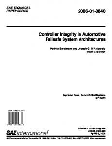
Fig. 1. pure::variants’ terminology
The Product Line’s commonalities and variabilities are described in the Problem Space, which reflects the desired range of applications (“product variants”) in the Product Line (the “domain”) and their inter-dependencies. Thus, when producing a product variant, the developer uses the problem space definition to describe the desired combination of problem variabilities to implement the product variant. A related Solution Space describes the Product Line’s artifacts and their relation to the Problem Space, i.e. rules for how platform elements are selected when certain values in the Problem Space are selected as part of a product variant. The used variant management tool pure::variants [8] captures the information required to manage variability and variants in several model types (see Figure 1). Feature models play a key role in this [2]. They allow a uniform representation of the Product Line’s variabilities and commonalities. Solution artifacts are described by family models, which enable the mapping of the Problem Space to different realizations. The variant model is used to describe an individual product. It describes the product’s features and values associated with those features, and it is used to derive the final product variant assets from the family models. 2.2
Safety Contracts
To express parts of the safety concept we are using a notation called safety patterns, which we would like to introduce here shortly: Safety contracts[7] are a technique for specifying fault propagation. The assumption and the promise of a contract[1] are expressed using safety pattern which are textual building bricks, with user filled attributes. The most commonly used pattern describes, that a combination of faults and failures does not occur in a run of the system. These expression sets may contain one or more faults and failures. none of {expr-set1, expr-set2,...} occurs the LTL semantics of this pattern are defined as: (G!e1 ∨ G!e2 ) ∧ (G!e3 ∨ G!e4 ), with expr set1 = {e1 , e2 } and expr set2 = {e3 , e4 }. I.e., that in every expr-set one fault occurs at most. The fault are generally assumed to be independent,
but dependence between them can be separately specified. There exists an abbreviated pattern which just considers a single expression-set, with identical semantics as described above: {expr-set} does not occur In a top-down approach the faults are typically expected defects in functions selected by experts. If they are refined to a particular level it needs to be shown that the selected hardware and software component match the expectations. In a bottom-up approach, the potential malfunctions of a component can be found in the safety manual or identified by techniques like FMEA (Failure Mode and Effect Analysis). Patterns are formally defined on traces, i.e. system runs with an evolution over its variables [4]. Hence, a requirement pattern restricts the possible runs of a system. Pattern 1 and its derived Pattern 2 state that only system runs in which the combination of malfunctions (stated in the expression sets) is absent are accepted. Oertel et.al [7] presented several contract templates that can be used to describe typical safety concepts. In this work we focus on the most commonly used template that is depicted in contract C1 and describes the propagation of input and internal faults (mf in the assumption) to a failure at the level of one of the component’s outputs. C1
A: none of {{mf 11 ...,mf 1n },..., {mf n1 ...,mf nm }} occurs. P: {output mf} does not occur.
The refinement of safety contracts can be checked automatically (see [3] and [1]). Furthermore, analyzes exist, that allow to check the satisfaction relation of a contract and a component [6].
3
Basic Idea
We demonstrate the basic idea on the example of an automotive light manager system. This gets redundant analog inputs from light sensors and calculates a lights on/off recommendation. Figure 2 depicts the functional safety concept (FSC) for the automatic light feature AutoLight, which should be used by multiple variants. The FSC is using a command which calculates the light recommendation and a monitor, which does the same, and compares the internal result with the light recommendation from the command. If the results differ, the valid signal will be set to false. Hence the systems requirement, to be robust against single point faults by detecting them with the valid signal can be formalized as a safety contract: C2
A: {more than 1 malfunction} does not occur. P: {light fail, valid fail} does not occur.
The Command subcomponent does not have any safety mechanisms itself, it just produces a wrong output if an internal fault occurs:
Functional Safety Concept
M1
{AutoDim}
light
Command
aIn1
{AutoLight} Alloc(ECU1,Task_CMD)
{AutoLight, AutoDim}
cmd_light M2 Monitor
aIn2
valid Alloc(ECU1,Task_CMD)
Alloc(ECU2,Task_MON)
Technical Safety Concept
Alloc(ECU1,Task_MON)
ECU1
TM1
TM2 Task_CMD
ECU2
TM3
TM4 Task_MON
Variant A: {AutoLight. AutoDim}
C3
TM1 ECU1
TM2 Task_CMD
TM4 Task_MON
Variant B: {AutoLight}
Fig. 2. One functional safety concept used by two variants A: {command fail} does not occur. P: {light fail} does not occur.
The Monitor subcomponent does only fail to produce a correct valid signal if the light input from the Command and the monitor both fail: C4
A: {light fail, monitor fail} does not occur. P: {valid fail} does not occur.
The safety concept assumes that faults of both subcomponents are independent: C5
A: TRUE P: independence{command fail,monitor fail}
The automatic light manager feature AutoLight shall be used within multiple variants. In the example we are considering only one additional feature called AutoDim, which darkens the central mirror in case of a directly preceding car. In Figure 2 two variants are displayed. Variant A uses the features AutoLight and AutoDim, variant B uses only AutoLight. The colors indicate the relation of the design element to the features in the family model. ECU2 (Electronic Control Unit) is optional and just available if feature AutoDim is selected while ECU1 is always part of the system. Also the allocations from the functional safety concept to the technical one are managed by features. In both variants the Command is mapped to ECU1, but the Monitor is mapped either to ECU1 or ECU2, depending on the availability of ECU2. From a functional viewpoint, both variants are correct (assuming that ECU2 has the possibility to host the monitor function) but are the variants still correct w.r.t. to the safety viewpoint? In the functional safety concept the malfunctions M1 and M2 are assumed to be independent. If there is a common cause, that leads to an occurrence of both malfunctions, the safety concept is incorrect. The
same assumptions on independence apply to the technical malfunctions TM1 - TM4. The mapping of the functional safety concept to the technical creates a relation between the functional malfunctions and the technical ones. If the function Command is mapped to ECU1 and the software task Task CMD a fault in either of them leads to the functional malfunction M1. If we are now mapping also the monitor task to ECU1 (and Task MON) a malfunction in ECU1 will damage the Monitor functionality and the Command functionality together, violating the safety requirement, that the system shall be robust against one fault. Hence, the created functional variant B is not correct in terms of the safety properties. That means in turn that the feature AutoLight can only be chosen in variants if also the AutoDim feature or another feature that places an additional suitable ECU is selected. We want to support the engineer to detect such problems directly while configuring variants, that’s why we create constraints for the variability models to prevent such configurations. We are considering independence violations caused by allocations. An allocation of a function f to a tuple of hardware and software components (H, S) is considered to be functionally correct if the behavior [[H]] ∩ [[S]] is a refinement of the functional specification [[f ]]. A violation is considered as a design fault in the system. In the following we assume that the functional correctness of an allocation has been successfully validated. Faults occurring during the execution of a component that lead to a violation of safety relevant functional requirements are represented as cut-sets in the safety contracts. The cut-sets do not contain any timing information regarding the occurrences of the faults in a trace. There exists a non-trivial relation between the cut-sets of the target components and the cut-sets of the functions. In the easiest case all target cut-sets immediately cause the functional fault. But there are cases in which the software may compensate hardware faults and vice versa. For instance, bit faults in memory can be detected by software that hold copies of relevant variables. An allocation is therefore correct with respect to independence, if there exists no part relation between any of the cut-sets of the allocation targets that were assumed to be independent in the functional safety concept. These rules can be integrated in the variability models to forbid variants that are not safe.
4
Modeling and Analysis using the SAFE Framework
We modeled the example, described in Section 3, by applying the SAFE tool platform provided by the SAFE Project 3 . We created the functional architecture using EAST-ADL, the corresponding technical hardware and software architecture using AUTOSAR, the safety extension for both of these models using SAFE. With pure::variants, also integrable into the SAFE tool platform, the variant management part was realized. The functional architecture in EAST-ADL is depicted in Figure 3 (middle). The logical structure of figure 2 is identically transferred. The LightManager FunctionType consists of two FunctionPrototypes, namely the Command and the 3
http://www.safe-project.eu/
Fig. 3. The functional architecture in EAST-ADL (middle), the corresponding safety extension in a SAFE model (right) and the technical architectures represented in an AUTOSAR model (right). Links modeled in attributes are represented as arrows.
Monitor function. Those functions are realized by the AUTOSAR SWCs with the identical names (see arrows attached to the realization links). The AUTOSAR model contains further elements for the whole light system of a car, like lightsensors, front light and even a front camera. For the safety case those elements need to be assumed interference free to the LightManager component Furthermore, the ECUs are modeled. Note, that we are following the commonly used paradigm to allocate functions first to software, and allocate the software to ECUs in a second step. The first allocation step is visible in Figure 3 but the second one is not since the part where these allocation relations are modeled in the AUTOSAR model is not displayed. Nevertheless, to analyze the correct realization of an functional safety concept by an technical one, also the hardware target needs to be known. The safety properties are stated in a SAFE model. For each functional component a safety extension is created which allows to capture the malfunctions of that component and a set of safety requirements. The malfunctions can be freely typed, in this case random faults are assumed in the component, i.e. that the result cannot be trusted. Typical other types are stuck-at, too late, or ommission. The FailurePropagation requirements and the MalfunctionIndependenceRequirement capture the safety contracts presented in section 3 (C1 − C4 ). The realization relations, the failure propagation requirements, the variable architecture and the resulting allocations are used as input for the variability models and for creating constraints for the variant management to ensure that only safe variants can be configured. Figure 4 shows the family model of the functional safety concept. It contains just the needed information from the variant management perspective to ensure the independence of the malfunctions M 1 and M 2. The constraint is also visible and it is read as compare the allocations of the Command and the Monitor and if they are distinct the constraint is sat-
isfied. It is continuously checked while configuring variants and if it evaluates to true, the variant complies to the functional safety concept. However, if the constraint evaluates to false, the common functional safety concept is violated by the technical realization of that currently configured variant. In order to show how this works in a tool environment, we present a scenario where a variant called Compact is stepwise configured until it complies to the common functional safety concept. The first configuration, depicted in Figure 5, shows the selection of the feature AutoLight and because of the fact that AutoLight demands a functional safety concept the constraint gets activated. Unfortunately, the variant has only ECU1 available on the technical architecture thus the tasks Tast CMD and Task MON can only be allocated to ECU1 why we have a single point of failure, contradicting the functional safety concept. The marker in Figure 5 on the right side shows that the constraint was evaluated to false. Furthermore, the marker’s tool-tip gives the related error message, saying M 1 and M 2 may have a common cause of failure. Note, from the functional point of view the variant is correct, but not from the safety point of view. If the configuration of variant Compact is continued and an additional feature like AutoDim is selected the following will happen (see Figure 6). The AutoDim selection causes beside the selection of the required software and other artifacts also the selection of the ECU2. Having ECU2 available allows for the allocation of Tast CMD and Task MON to distinct ECUs. Hence, the single point of failure disappears and the common functional safety concept gets respected. There are also other configurations possible with features like AutoLight and Automatic High/Low Beam, which lead also to the selection of an additional ECU. That means, as long as an additional ECU is available due to the selection of an additional feature, the feature AutoLight can be part of a valid configuration of a variant. In order to respect the common functional safety concept in any case, the developers should think about whether the selection of AutoLight requires ECU2 directly. Adding this information into the variability models would ensure that a variant having just the feature AutoLight would be also safe.
5
Conclusion & Outlook
In this paper we presented an approach to transfer the advantages of product line engineering in the context of safety critical systems. A functional safety concept can be realized on different technical implementations. We focused on
Fig. 4. Family model containing the necessary information and the constraint, which ensures that only variants can be configured, respecting the functional safety concept.
Fig. 5. A configuration of the variant called Compact which is invalid as it violates the functional safety concept as visualized by the marker showing the error message “M 1 and M 2 common cause.”
violations of safety requirements due to allocations of software to hardware, that is mainly driven by functional needs. While configuring a system, variants that do not respect the safety requirements cannot be configured. We applied this approach to the pure::variants tool, the leading PLE tools in the industry [2]. The safety extensions used for storing malfunctions and their propagation have been developed in the European project SAFE and are subject to be integrated within the EAST-ADL specification language. Although we sketched the approach based on an allocation example, it is capable to deal with arbitrary failure definitions and propagation. To do this, a generalization of the correctness definition of the realization of functional safety concepts by technical ones is planned. Furthermore, the approach shall be formally integrated in the domain of trace semantics, allowing to reason also about timed safety properties. This would require a step from pure cut-sets to cutsequences, but drastically increase the preciseness of the safety specification.
ACKNOWLEDGEMENTS This document is based on the SAFE and SAFE-E projects. SAFE is in the framework of the ITEA2, EUREKA cluster program Σ! 3674. The work has been funded by the German Ministry for Education and Research (BMBF) under the funding ID 01IS11019, and by the French Ministry of the Economy and Finance (DGCIS). SAFE-E is part of the Eurostars program, which is powered
Fig. 6. A valid configuration of the variant called Compact respecting the functional safety concept. Due to the selection of the AutoDim feature the Command and the Monitor are allocated to different ECUs.
by EUREKA and the European Community (ID 01—S1101). The work has been funded by the German Ministry of Education and Research (BMBF) and the Austrian research association (FFG) under the funding ID E!6095. The responsibility for the content rests with the authors.
References 1. Benveniste, A., Caillaud, B., Nickovic, D., Passerone, R., baptiste Raclet, J., Reinkemeier, P., Sangiovanni-vincentelli, A., Damm, W., Henzinger, T., Larsen, K.: Contracts for systems design. Tech. rep., Research Centre Rennes Bretagne Atlantique (2012) 2. Berger, T., Rublack, R., Nair, D., Atlee, J.M., Becker, M., Czarnecki, K., Wsowski, A.: A survey of variability modeling in industrial practice. In: Proceedings of the Seventh International Workshop on Variability Modelling of Software-intensive Systems. p. 1. ACM Press New York, NY, USA, Italy (2013), http://dl.acm.org/ citation.cfm?doid=2430502.2430513 3. Damm, W., Hungar, H., Josko, B., Peikenkamp, T., Stierand, I.: Using contractbased component specifications for virtual integration testing and architecture design. In: Design, Automation Test in Europe Conference Exhibition (DATE), 2011. pp. 1 –6 (march 2011) 4. H. Hungar: Compositionality with strong assumptions. In: Nordic Workshop on Programming Theory. pp. 11–13. M¨ alardalen Real–Time Research Center (November 2011) 5. Linden, F.J.v.d., Schmid, K., Rommes, E.: Software Product Lines in Action: The Best Industrial Practice in Product Line Engineering. Springer-Verlag New York, Inc., Secaucus, NJ, USA (2007) 6. Oertel, M., Kacimi, O., B¨ ode, E.: Proving compliance of implementation models to safety specifications. In: Proceedings of the ERCIM/EWICS/ARTEMIS Workshop on Dependable Embedded and Cyber-physical Systems and Systems-of-Systems (DECSoS14) (to be published 2014) 7. Oertel, M., Mahdi, A., B¨ ode, E., Rettberg, A.: Contract-based safety: Specification and application guidelines. In: Proceedings of the 1st International Workshop on Emerging Ideas and Trends in Engineering of Cyber-Physical Systems (2014) 8. pure-systems GmbH: pure::variants eclipse plugin user guide (2014), http://www.pure-systems.com/fileadmin/downloads/pure-variants/doc/ pv-user-manual.pdf