AbstractâIn wireless networks, broadcasting is a fundamental communication primitive for network management and informa- tion sharing. However, in ...
2015 IEEE Conference on Computer Communications (INFOCOM)
Revisiting Overlapped Channels: Efficient Broadcast in Multi-channel Wireless Networks Jae-Han Lim1 , Katsuhiro Naito2 , Ji-Hoon Yun3 and Mario Gerla1 1
University of California, Los Angeles 2 Aichi Institute of Technology 3 Seoul National University of Science and Technology Abstract—In wireless networks, broadcasting is a fundamental communication primitive for network management and information sharing. However, in multi-channel networks, the broadcast efficiency is very poor as devices are distributed across various channels. Thus, a sender tries all channels for broadcasting a single message, which causes large overhead. In this paper, we propose a novel scheme for efficient broadcast in multichannel networks. Our scheme leverages the overlapped band, which is the frequency range that partially overlapped channels (i.e., adjacent channels) share within their channel boundaries. Specifically, a sender advertises the rendezvous channel through the overlapped band of adjacent channels; the message sharing via broadcast is done on the rendezvous channel. Our scheme employs Signaling via Overlapped Band (SOB), which defines a new signal processing mechanism for communication via the overlapped band. SOB is integrated with MAC layer mechanisms: 1) Reserve Idle Spectrum Fragment (RISF) to reduce waiting time, 2) Reinforce Switch Notification (RSN) to reduce the residing time at a wrong channel, and 3) Multi-sender Agreement on Rendezvous CHannel (MARCH) to support multisender broadcasts. We implemented our scheme on the SORA platform. Experiment results validated communication through the overlapped band. Intensive simulation studies showed that our scheme drastically outperformed previous approach. Index Terms—802.11 Wi-Fi, overlapped band, multi-channel network, broadcast
I. I NTRODUCTION Currently, an explosive increase in the use of mobile devices (e.g., smart phone, tablet PC, and laptop) expanded the demand for Wi-Fi services. To meet this demand, Wi-Fi devices must exploit multiple channels. In a 2.4GHz ISM band, IEEE 802.11g [1] defines 13 channels, of which maximum three channels (e.g., 1, 6, and 11 in U.S.A.) are orthogonal. However, it is difficult to fit all Wi-Fi users into only three channels in densely populated area [2]. Moreover, it is hard to manage the channels of private Access Points (AP) and mobile devices. Thus, it is inevitable to use adjacent, non-orthogonal channels (i.e., partially overlapped channel) despite Adjacent Channel Interference (ACI). Previous researches have found support for the validity of this argument. For example, [3] showed that APs exploited non-orthogonal channels through measuring AP deployments. In addition, several previous works indicated that using non-orthogonal channels helped improve network performance [4] [5] [6]. [2] found that Wi-Fi devices were distributed over overlapped channels and proposed a mechanism for alleviating collision between overlapped channels. In wireless networks, broadcasting is a fundamental communication mechanism for topology maintenance and data dissemination. For example, hello messages are broadcasted
978-1-4799-8381-0/15/$31.00 ©2015 IEEE
for topology maintenance; beacons are periodically broadcasted for advertising vehicle status in vehicular networks. However, despite its wide applicability, broadcasting in multichannel networks poses a new technical challenge: a sender and receivers must rendezvous on the same channel. A naive solution is that a sender tries all channels for broadcasting a single message. However, this approach requires a great number of transmissions, which leads to huge network overhead and power consumption. We quantify the limitation of this approach using QUALNET 6.1 [8]. To be specific, when 100 users in the range of each other periodically broadcast beacon messages every 150ms, its Packet Delivery Ratio (PDR) is only 70% even though a radio interface spends 75% of its time for transmissions and receptions. This means that the broadcast performance is not satisfactory considering the great amount of radio resources put in for broadcast. Thus, we need to reduce the redundant transmissions to increase the broadcast efficiency. The other approach is that a sender and receivers periodically meet at the static Common Control Channel (CCC); and the sender broadcasts a message at the CCC. However, as the large demand for broadcast can cause serious congestion at the CCC, the dedicated channel may not fit for exchanging data (a.k.a. a single point of failure) [12]. Using the channelhopping mechanisms can solve the bottleneck of the static CCC, but it also has a limitation in that repetitive transmissions are required for broadcasting a single message [12] [13] [14]. This is because a sender cannot identify the channels of its neighbors. Similar to the naive solution, the repetitive transmissions induces large overhead and power consumption. At this point, we can raise an important question: “can we broadcast a message with the small number of transmissions while avoiding the single point of failure in multi-channel networks?” To answer this question, we propose a novel broadcast scheme that exploits an overlapped band, which means the range of frequencies that partially overlapped channels (i.e., adjacent channels) share within their own channel boundaries. Previously, the overlapped band has been considered harmful since a signal in the overlapped band causes ACI. However, in our counter-intuitive approach, we leverage the overlapped band for conveying information to other devices in adjacent channels. Specifically, our scheme enables information delivery to multiple adjacent channels with a single transmission through the band that the multiple adjacent channels commonly share. Thus, we can significantly
1984
2015 IEEE Conference on Computer Communications (INFOCOM)
reduce the number of transmissions needed for information delivery to multiple channels. The proposed scheme consists of two steps: 1) a sender determines a rendezvous channel and advertises it through the overlapped band; receivers jumps the advertised channel, and 2) the sender broadcasts a message at the advertised channel1 . However, it is non-trivial to ensure the successful communication of the channel information when a sender and a receiver use adjacent channels. In most communication systems, to extract a signal of a specific band, a receiver rejects frequencies outside the band using Low-Pass Filter (LPF). But, if a sender and a receiver exploit adjacent channels, their bands are not aligned with each other. Thus, the receiver might attenuate a fraction of a transmitted signal during filtering process, which leads to signal distortion. To address this problem, our scheme adopts a new signal processing mechanism at the physical layer, Signaling via Overlapped Band (SOB). In SOB, a sender divides a channel into multiple sub-channels with an equal bandwidth and loads information on each sub-channel. If the overlapped band between a sender and a receiver encompasses more than one sub-channel, the receiver’s LPF passes all frequencies of the sub-channel. Thus, a receiver can get a signal of the carried information without loss. Even if a receiver gets a signal without loss after filtering, in current channelized network protocols such as IEEE 802.11b/g, the receiver cannot decode the signal if using a different channel with a sender. To tackle this issue, we define a new PHY frame, which is called Rendezvous Signal (RS), and establish a signal processing procedure for en/decoding the RS reliably. At the MAC layer, we employ three novel mechanisms to further improve the broadcast efficiency by addressing the following three problems. First, a sender might have to wait for a long time before accessing the channel in multi-channel networks. This is because the busy medium may come from the co-channel interference as well as ACI; the sender must wait until the devices in the same and adjacent channels do not access the channel. To address this challenge, the proposed scheme employs Reserve Idle Spectrum Fragment (RISF), where a sender prevents other devices from occupying the idle spectrum fragments within the sender’s channel. Second, when failing in decoding RS, devices switch to the wrong channel, which leads to rendezvous failure with a sender. To remedy this problem, our scheme employs Reinforce Switch Notification (RSN), which reduces the residing time in the wrong channel. Third, when multiple senders start their broadcast procedures at a similar time, receivers might fail to make rendezvous with some of the senders, which causes the reception failure of broadcast messages. This is because the senders determine their own rendezvous channels independently, but the receivers can make rendezvous with only one of them at a time. To meet this challenge, the proposed scheme adopts Multi-sender Agreement on Rendezvous CHannel (MARCH), ensuring that only one rendezvous channel is used by the 1 Even if our design and implementation is based on 802.11g network, this work can be easily extended to other network systems that exploit overlapped channels (e.g., 802.11b and Wi-Fi in Whitespaces [21]).
multiple senders at a similar time. We have implemented the proposed scheme on the SORA software radio platform [7] and QUALNET simulator [8]. We verify the feasibility of the communication via the overlapped band between different channels using the SORA platform; we feed the experiment results into the physical layer model of RS reception in QUALNET. In addition, intensive simulation studies show that the proposed scheme achieves outstanding performance enhancement over previous approach [14] - 108% rise in terms of Packet Delivery Ratio (PDR), 92% reduction in terms of delay, and 87% reduction in terms of time that a radio interface spends for broadcasting. We also show that our scheme can support vehicular beacon exchanges well in multi-channel networks. In summary, the contributions of this paper are as follows: • Propose a novel broadcast scheme that requires the small number of transmissions and avoids a single point of failure in multi-channel networks. • Explore the feasibility of information delivery through the overlapped band between partially overlapped channels. • Propose three new mechanisms at the MAC layer to fully exploit the advantage of SOB. • Implement the proposed scheme on the SORA platform and evaluate the proposed scheme with the implemented testbed. The remainder of this paper is organized as follows. In section II, we review previous works for broadcasting in multichannel networks. In section III, we introduce the overview of our scheme. In section IV, we explain a new signal processing mechanism at the physical layer, called SOB. In section V, we introduce three MAC-layer mechanisms that are integrated with SOB. In section VI, we evaluate the proposed scheme. This paper is concluded in section VII. II. R ELATED W ORKS Several works have been proposed for broadcasting in multi-channel networks based on a broadcast schedule [9] [10]. [9] proposed a scheduling mechanism for broadcasting in multi-channel wireless ad-hoc networks in order to minimize end-to-end delay. However, [9] assumed that every device knew the channels of its neighbors, which must be updated frequently via message exchanges in mobile networks. [10] formulated a multi-channel multi-radio broadcast problem as a minimum spanning problem in simplicial complexes. However, [10] made an assumption that all devices had multiple radios, which increased the cost A number of works relied on a common control channel (CCC), on which devices broadcast a message in multichannel networks [11] [12] [13] [14]. [11] proposed to establish CCC via negotiation among devices (i.e., pre-defined sequence). However, the negotiation could be realized via message exchanges, which induced large network overhead in mobile networks. The CCC could also be established via channel hopping techniques without the negotiation [12] [13] [14]. Despite no signaling overhead for negotiation, it took some time before making rendezvous; redundant transmissions were required for broadcasting a single message since a sender could not identify the current channels of its neighbors.
1985
2015 IEEE Conference on Computer Communications (INFOCOM)
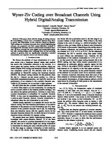
Fig. 1. Overall procedure of the proposed broadcast scheme
III. OVERVIEW
OF
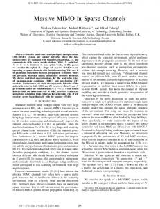
Fig. 2. Benefit of using overlapped band: a single transmission at channel 3 can reach all devices in channel 3∼5.
P ROPOSED S CHEME
Fig.1 illustrates an overall procedure for broadcasting a single message (we will call this procedure ’broadcast procedure’ throughout the paper). In the advertisement step, a sender selects its own channel number for rendezvous (i.e., rendezvous channel)2 and shares it with neighbors. When receiving the channel number, the neighbors switch their radio channels to the received channel. In the data transmission step, the sender jumps to the rendezvous channel and broadcasts the message. If using a typical Wi-Fi communication system, a sender should try all channels for transmitting the rendezvous channel in the advertisement step. Consequently, the number of transmissions grows linearly with the number of channels, which in turn increases network overhead. The proposed scheme meets this challenge by adopting Signaling via Overlapped Band (SOB), which is a new signal processing procedure at the physical layer. Specifically, a sender divides its channel into multiple sub-channels with an equal bandwidth (e.g., two sub-channels with 10MHz bandwidth in Fig.2) and transmits the rendezvous channel through each sub-channel. If the overlapped band between the neighbor and the sender encompasses at least one sub-channel, the neighbor can receive the rendezvous channel (e.g., devices in channel 1∼5 in Fig.2). As several adjacent channels share the same subchannel in 2.4GHz ISM band (e.g., channel 1∼3 shares the sub-channel 1 in Fig.2), the sender can deliver its rendezvous channel to the neighbors in several adjacent channels with a single transmission. Therefore, using SOB, we can reduce the number of transmissions for the advertisement. We will explain the benefit of SOB with a simple example. In this example, we assume that the sub-channel size is 10MHz and a sender should advertise its rendezvous channel to devices in 13 channels. First, the sender transmits the rendezvous channel in channel 3 using SOB; neighbors in channel 1∼5 can receive the rendezvous channel, as shown in Fig.2. Similarly, the sender transmits the rendezvous channel in the channel 8 and 13 using SOB; neighbors on channel 6∼10 and channel 11∼13 receive the channel number, respectively. Hence, we can reduce the number of transmissions needed for 2 In our scheme, a sender randomly selects the rendezvous channel. This is because receivers freeze their radios when receiving the RS. This means that every channel has an equal congestion level in the data transmission step. However, when considering external interference (e.g., microwave), the channel conditions are heterogeneous; we need to consider the external interference in channel selection. The details on this solution will be our future work.
the rendezvous channel advertisement from 13 to 3. The benefit of SOB can be realized via reliable communications through the overlapped band of adjacent channels, which is not supported in current 802.11 standard [1]. Thus, we define a new signal processing mechanism in SOB to enable communication through the overlapped band of the adjacent channels. Specifically, we define a special PHY frame, which is referred to as Rendezvous Signal (RS), for exchanging rendezvous channel through the overlapped band of adjacent channels. RS is en/decoded with a simple on/off keying, which is known to be reliable even in poor channel conditions. The details of signal processing mechanism will be explained in section IV. Our scheme also employs three mechanisms at the MAC layer to fully exploit the benefit of SOB. First, our scheme employs Reserve Idle Spectrum Fragment (RISF) to reduce the long waiting caused by ACI of multiple channels. Second, we adopts Multi-sender Agreement on Rendezvous CHannel (MARCH) to mitigate rendezvous failure with senders when multiple senders start their broadcast procedures at a similar time. Third, we incorporate Reinforce Switch Notification (RSN) to mitigate the negative effects of switching to the wrong channel when failing in decoding RS. We will explain these three mechanisms in the section V in more detail. IV. S IGNALING VIA OVERLAPPED BAND As explained in section III, we can reduce the number of transmissions in the advertisement step when adopting Signaling via Overlapped Band (SOB), where devices exchange information through the overlapped band of adjacent channels. The benefit of SOB can be realized only when communication via the overlapped band is possible. However, the current 802.11 standard [1] does not support the communications between adjacent channels. To enable the communications between adjacent channels, we propose a novel signal processing mechanism in SOB3 . Specifically, a sender makes a RS frame for annotating the frame with a rendezvous channel and loads the frame on each sub-channels of its channel. Then, the receiver uses Digital Band-Pass Filter (D-BPF) to detect the RS on its current channel. The receiver performs detection mechanisms for the output of D-BPF. If detecting RS, the receivers decode a rendezvous channel number. From now on, we will explain 3 We can implement this system by adding digital filters and decoding/encoding module in digital signal processing area. Thus, the implementation of this system is not complicated.
1986
2015 IEEE Conference on Computer Communications (INFOCOM)
Fig. 3. Frame format of Rendezvous Signal Fig. 5. Consider guard bands when sizing the bandwidth of a RS frame
Fig. 4. Generation Procedure of Rendezvous Signal Fig. 6. Reception Procedure of Rendezvous Signal
a frame format of the RS and signal processing procedures for generating/receiving the RS. A. Frame Format of Rendezvous Signal Fig.3 illustrates the frame format of Rendezvous Signal. RS consists of four parts: 1) Short Training Signal (STS), 2) Long Training Signal (LTS), 3) Threshold Signal (TS), and 4) Data Signal (DS). STS consists of 10 identical symbols and is used for RS detection. LTS consists of two identical symbols and a cyclic prefix, which is equal to the first half of a LTS symbol. LTS is used to find the exact arrival time of RS using a matched filter [15]. TS consists of two symbols, which are used for calculating a threshold to declare that received data symbol represents one or zero. DS is used for expressing the rendezvous channel and encoded with on/off keying. Specifically, rendezvous channel is expressed with bit sequence; high and low symbol energy is used for expressing one and zero, respectively. B. Procedure for Generating Rendezvous Signal Fig.4 illustrates a RS generation procedure. First, a sender makes a RS frame according to the format in Fig.3. Second, the sender determines the bandwidth of a sub-channel and fit the bandwidth of the frame into the bandwidth of the subchannel. Third, a sender relocates the RS frame into each subchannel. In determining the bandwidth of the sub-channel, we should firstly select the required number of RS transmissions for advertising the rendezvous channel. More specifically, the bandwidth affects the number of channels where the receiver filter in the radio front-end (i.e., analog filter) can extract the RS without loss. Recall that the RS signal loss does not happen when the overlapped band between a sender and a receiver includes more than one sub-channel. The number of channels, in turn, affects the required number RS transmissions. For example, when using 10MHz sub-channel in IEEE 802.11g, a receiver can extract RS without loss during filtering process when the channel spacing between a sender and a receiver is no more than two, as shown in Fig.2. In this case, a single RS transmission can reach to five adjacent channels (e.g., channel
1∼5 when sending at channel three in Fig.2); the required number of RS transmission is three for covering 13 802.11g channels. It is noted that distortion exists at the edge of the band in the analog filter. Hence, typical Wi-Fi devices allocate 1.875MHz in both edges of a channel as a guard band [16]. Therefore, when fitting the RS frame into the sub-channel, we have to consider these guard bands so that the RS frame in the subchannel can be transmitted without distortion4 . For example, when we use 10MHz sub-channel, the band that we can use for carrying RS is only 6.25MHz (=10-1.875x2), as shown in Fig.55 . C. Procedure for Receiving Rendezvous Signal A receiver gets a rendezvous channel from RS according to the three-step procedure, as depicted in Fig.6. In the first step, a receiver performs a low-pass filtering in the radio frontend (i.e., filtering with analog filter) and checks whether the channel is busy or not. If detecting busy channel, the receiver continues to the second step6 . Otherwise, the receiver does not proceed the procedure and discards the signal. In the second step, the receiver finds RS using ‘RS detection algorithm’ within the signal. Similar to the first step, the receiver goes to the next step only if finding RS. In the third step, the receiver decodes the rendezvous channel from RS according to ‘RS decoding algorithm’. The RS detection algorithm is composed of two phases: 1) a digital filtering phase and 2) a detection test phase. In 4 Our scheme exploits the analog filter without modification. We only modify the digital part, which is more flexible in modification. (e.g., software defined radio). 5 The transmission rate is proportional to the data bandwidth, thus, the delay for RS transmission grows. However, as the size of RS frame is very small, the increased delay is also short. For example, when we use 6.25MHz band for data bandwidth, the delay for transmitting RS is only 205us even with the most reliable modulation (i.e., lowest rate). 6 A receiver should also be able to receive typical Wi-Fi signal with fullchannel bandwidth. For this purpose, before moving on to step 2, a receiver feeds a signal into the reception procedure of typical 802.11 communication. system. If passing CRC, a receiver recognizes that the busy medium comes from the typical Wi-Fi signal and does not go to step 2. Otherwise, a receiver goes to step 2.
1987
2015 IEEE Conference on Computer Communications (INFOCOM)
Fig. 7. Detection test of Rendezvous Signal Fig. 8. Reserve Idle Spectrum Fragment
the digital filtering phase, a receiver filters the sub-channel of RS from the analog filter output via Digital Band-Pass Filter (D-BPF). However, the receiver cannot identify the center frequency of the sub-channel since the center frequency changes according to the channel of a RS sender, which the receiver does not know. To meet this challenge, the receiver must conduct filtering several times by changing the configuration of D-BPF, assuming that the RS is sent on one of adjacent channels. For example, when residing in channel 3 and using 10MHz as the sub-channel size, a receiver can receive RS only if a sender transmits the RS in one of five channels (channel 1∼5). Thus, the receiver conducts filtering assuming that RS is sent on one of the five channels. As a result, a receiver performs filtering three times7 by configuring the center frequency of the D-BPF with 2412MHz, 2407MHz, and 2017MHz for each filtering. In the detection test phase, a receiver checks whether the RS is detected or not in each filter output of the digital filtering phase. As illustrated in Fig.7, a receiver performs two RS detection tests and declares that RS is detected if passing both tests. The first test is conducted at STS and consists of three sub-tests: 1) energy detection test, 2) auto-correlation test, and 3) cross-correlation test. In each sub test, the receiver calculates energy, auto-correlation, and cross-correlation with known sequence, respectively. If the calculated value is larger than the pre-defined threshold8 , the receiver declares pass in each sub-test. When passing three sub-tests, the receiver declares the pass in the first test. The receiver performs the second test after receiving DS. Specifically, the receiver checks whether the channel is busy or not during DIFS. The second test is for screening normal Wi-Fi signals that falsely pass the first test9 . Thus, as the length of normal Wi-Fi signal is longer than RS, we make the receiver declares pass in the second test if the channel is idle during DIFS. The RS decoding algorithm consists of two steps. In the first step, a receiver calculates a threshold by averaging the energy of two symbols in TS. This is because the first and the second symbol in TS represents high and low energy, respectively. In the second step, the receiver decodes each symbol in DS by comparing the symbol energy with the calculated threshold. If the symbol energy is larger than the 7 Filtering is performed three time rather than five since one configuration can cover multiple cases. For example, 2422MHz can cover the cases for channel 2 and 4. 8 We use threshold values similar to those of normal Wi-Fi transceiver [15], but need to customize the values according to the bandwidth of a RS frame. 9 This is because the first test is very similar to the normal 802.11 preamble test. Thus, even if the band of normal Wi-Fi signal and RS is not aligned, receivers may falsely declare RS detection, which we have observed during our measurement with SORA.
threshold, the corresponding symbol represents one, and vice versa, for representing zero. If the energy is equal to the threshold, the symbol is randomly declared to one or zero with equal probability. V. M ECHANISMS AT THE MAC L AYER In this section, we introduce three novel mechanisms at the MAC layer: RISF, RSN, and MARCH, which are integrated with SOB to fully exploit the benefit of SOB. A. Reserve Idle Spectrum Fragment In Carrier Sensing Multiple Access with Collision Avoidance (CSMA/CA), devices must wait when the medium is sensed to busy. In multi-channel networks, the medium can become busy due to interferences in the same channel as well as the adjacent channels. Thus, the device might wait for a long time for accessing the medium in the multi-channel networks. To meet this challenge, we propose Reserve Idle Spectrum Fragment (RISF) to reduce such long waiting time by reserving idle spectrum within a channel until transmitting a message. When generating the message, a device checks whether the current channel is busy or not. If the medium is idle, the device follows a normal CSMA/CA mechanism. Otherwise, the device starts RISF and ends only after they find that all spectrum fragments become idle. As shown in Fig.8, RISF consists of two phases: 1) a monitoring phase, 2) a reservation phase. In the monitoring phase, a device checks which spectrum fragments are idle in its current channel10 . In the reservation phase, the device transmits a jamming signal in idle fragments for reservation(e.g., 3rd and 4th fragments in the reservation phase of Fig.8). Here, the jamming signal is simple repetition of Pseudo Number (PN) sequence, which is encoded with on-off keying and detected with an energy detection. Then, when detecting the busy medium on those fragments, other devices cannot access the channel that shares the fragments (e.g., Dev 2 in Fig.8). During the reservation phase, a busy spectrum fragment becomes idle due to the transmission end in adjacent channels. In this case, a device must also reserve the fragment as well as previous idle fragments by sending jamming signals in those fragments. The device keeps transmitting the jamming signal until all fragments become idle within its channel. When finding all fragments are idle, the device sends its message without random backoff. 10 For spectrum analysis and reservation in RISF, we divide a channel into multiple spectrum fragments and set the bandwidth of the fragment to be the minimum sharing bandwidth between adjacent channels.
1988
2015 IEEE Conference on Computer Communications (INFOCOM)
Fig. 9. Rendezvous failure when multiple devices start broadcast procedure at a similar time
To maintain the reservation, a device must monitor its channel, while keep transmitting a jamming signal. However, current mobile devices exploit the half-duplex antenna, thereby not being able to transmit a signal and listen to the channel simultaneously. To meet this challenge, a device flips between RX and TX mode frequently. In other words, the device must keep switching between the monitoring phase and reservation phase frequently. For maintaining the reservation, the length of RX mode must not be larger than minimum waiting time for accessing the channel (e.g., DIFS in 802.11g). Thus, we set the flipping interval to the value that is slightly shorter than the minimum waiting time. B. Reinforce Switch Notification Sometimes, a receiver might jump to the wrong channel if a RS decoding error or false RS detection (i.e., false alarm) happens. When jumping to the wrong channel, the receiver cannot receive the message that a sender broadcasts. Moreover, the receiver unnecessarily changes its radio channel when the false alarm happens, which leads to missing the opportunity to receive data messages in the current channel. To address this problem, we propose Reinforce Switch Notification (RSN) that reduces the residing time in the wrong channel. Specifically, after transmitting RS, a sender temporarily jumps to the rendezvous channel and transmits Notification Signal (NS). Then, the sender jumps to the next RS transmission channel or the rendezvous channel according to the current step in its broadcast procedure. Here, NS is the repetition of PN sequence, which is en/decoded with simple on-off keying and detected with correlation with a known sequence. If detecting the NS within a predefined time11 , the receiver validates the current switch. Otherwise, the receiver goes back to its original channel. C. Multi-sender Aggreement on Rendezvous Channel Until now, we focus on the design when a single device broadcasts a message. However, in practical situations, multiple devices try to broadcast their messages at a similar time. In this case, one device (e.g., dev 2 in Fig.9) may start its broadcast procedure before completing the broadcast 11 As
a sender transmits NS after switching channel and performing RISF, the pre-defined time can be calculated as the sum of channel switching delay and the waiting time in RISF. The upper bound of the waiting time is equal to the maximum occupation time of a spectrum fragment, which is equal to the transmission delay of the longest MAC frame.
procedure of the other device (e.g., dev 1 in Fig.9). This situation can cause a rendezvous failure between a receiver and a sender (e.g., dev 3 fails in rendezvous with dev 2 at the data transmission step in Fig.9) This is because multiple senders determine their rendezvous channels independently (e.g., dev1 (dev2) selects channel 5 (10) in Fig.9); but receivers must follow only one of the rendezvous channels. A solution to this problem is the agreement on the rendezvous channel among multiple devices that start broadcast procedures at a similar time. The devices can achieve the agreement by following the command of RS when receiving the RS from the other device (‘RS initiator’). Specifically, when receiving the RS, other senders (‘RS followers’) suppress their RS transmissions and jump to the received rendezvous channel. Then, the RS followers broadcast their messages when all receivers are gathered in the channel12 . It is noted that devices might receive multiple RSs from different senders. Specifically, in the received rendezvous channel, the devices might receive RS from others that do not suppress their RS transmissions yet. Thus, the devices may be confused which channel they must jump into. To avoid the confusion, the devices jump into the rendezvous channel only when receiving RS firstly, and does not react to other RSs until completing the current broadcast procedure. VI. P ERFORMANCE E VALUATION In this section, we implement and evaluate a signal processing procedure for RS generation/reception on the SORA platform [7] to validate the communication via an overlapped band of adjacent channels. Next, we evaluate the proposed scheme in various network conditions and compare the scheme with previous work using QUALNET 6.1 [8]. In the QUALNET, we feed the SORA experiment results into a physical layer model for RS reception. Throughput this section, we set the bandwidth of the sub-channel to 10MHz, the bandwidth of each channel to 20MHz, the number of channels to 13. Thus, a pair of devices can communicate with each other through overlapped band when center frequency spacing is equal to or less than 10MHz. A. Validation of Communication between Adjacent Channels In the experiment, we exploit two SORA devices: one as a sender and the other as a receiver. For validation, we derive three performance metrics under different Signal to Noise Ratio (SNR) levels and center frequency spacing between a sender and a receiver: 1) false alarm probability (pf a ), 2) probability of mis-detection (pm ), and 3) probability of decoding error (pe ). pf a is defined as a fraction of RS detections among all detection tests even if a sender does not transmit a RS. pm is defined as a fraction of RSs that a receiver expects to detect but fails in detection. pe is derived as a fraction of RSs that fail in decoding the rendezvous channel among all detected RSs. 12 All receivers are gathered at the rendezvous channel when a RS initiator starts its data transmission step. As the RS initiator broadcasts a message in data transmission step, RS followers recognize the gathered time by receiving the broadcast message from the RS initiator. As the message transmission can be initiated only by the RS initiator in the rendezvous channel, the reception time means that all receivers are gathered in the rendezvous channel.
1989
2015 IEEE Conference on Computer Communications (INFOCOM)
0.0010
0.0006
0.0004
0.0002
0MHz spacing 5MHz spacing 10MHz spacing
0.16
Probability of decoding error
Probability of mis detection
0.0008
False alarm probability
0.5
0.20
0MHz spacing 5MHz spacing 10MHz spacing
0.12
0.08
0.04
0MHz spacing 5MHz spacing 10MHz spacing
0.4
0.3
0.2
0.1
0.0000 2
4
6
8
10
12
14
16
18
20
0.00
0.0 2
4
6
8
10
SNR
(a) pf a
12
SNR
14
16
18
20
2
4
6
8
10
12
14
16
18
20
SNR
(b) pm
(c) pe
Fig. 10. (a)pf a , (b)pm , and (c)pe according to SNR when a frequency spacing between rx and tx channels is 0MHz, 5MHz, and 10MHz
In Fig.10(a), we observe that pf a is almost close to zero. This is because a receiver must pass two tests for declaring a detection success: 1) preamble detection at Short Training Signal (STS) and 2) energy detection after receiving the RS. The first test is similar to the preamble detection of IEEE 802.11 standard [15], except that we perform the test with signal of overlapped band. The second test is for avoiding false alarm that comes from normal Wi-Fi signal. As our system needs one more step for detecting a signal than a normal 802.11 preamble detection, pf a in our experiment are less than those of 802.11 detection (e.g., pf a is 0.005 when SNR is around 3dB and zero when SNR is larger than 4dB [17]). In Fig.10(b), we notice that the pm is less than 5% in all experiment settings. Moreover, in the practical SNR range (≥ 10dB) [17], the detection error is less than 2% for all center frequency spacing settings. In Fig.10(c), we observe that pe is relatively high when SNR is 3dB, but pe is close to zero in practical SNR range. From these observations on pf a , pm , and pe , we can verify the feasibility of communications via overlapped band between adjacent channels. It is noted that the pf a , pm , and pe increase as the center frequency spacing between a sender’s channel and a receiver’s channel rises. This is because the filter in the RF front-end (e.g., XCVR2450 in our experiment) is not an ideal filter. Specifically, the frequency response of the realistic filter is not a perfect rectangular shape: the gain decreases as the frequency is getting away from the center frequency, and decreases rapidly around the cut-off frequency [18]. However, as the frequency spacing increases, frequency corresponding to an overlapped band is getting far from the filter’s center frequency. Thus, signal distortion increases as the spacing rises, which leads to higher pf a , pm , and pe . B. Improvement over Previous Work We evaluate the proposed scheme in various network conditions through QUALNET 6.1. We use two-ray ground model as a propagation model. In the PHY layer settings, we use IEEE 802.11g physical layer for transmitting and receiving messages through 20MHz channel. Moreover, we use the SORA experiment results for the physical layer model for RS reception that exploits 10MHz sub-channel13 . In the MAC get pf a , pm , and pe outside the tested SNR range, we use interpolation and extrapolation techniques. 13 To
layer settings, we use default values that are defined in IEEE 802.11g (e.g., CW, SIFS, and slot size). Devices are distributed across various channels, which are selected uniformly at random among 13 channels. We compare our scheme with BRACER [14], which outperforms the other previous works for broadcasting with a single radio interface in multi-channel networks14 . Each simulation is iterated by 20 times; we get 95% confidential interval from the iterations. We get three performance metrics in the simulation: 1) Packet Delivery Ratio (PDR), 2) delay, and 3) busy radio ratio. We define PDR as a fraction of the devices that successfully receive a broadcast message. Delay is referred to as an interval between a message generation and a message reception. The busy radio ratio is defined as a fraction of time in which a radio interface is in the busy state (i.e., reception, transmission, or busy channel detection states). From the busy radio ratio, we can infer three important points. First, we can infer the device energy consumption since radio in busy state consumes much more power than in idle state. Second, when there are only broadcast traffic, we can infer how much channel resources are used for the broadcast. Finally, from the simple calculation, ‘1 - busy radio ratio’, we can infer how much time the radio can be used for other purpose, such as unicast data transmission. The three metrics are derived according to three independent variables: 1) the number of users, 2) the source rate, and 3) the unicast traffic that coexists with the broadcast traffic. The typical settings on the variables are 40 users, 7.5 (pkt/sec), and no unicast traffic. To isolate the effect of each variable, we change the variable while fixing others to the typical settings. 1) The number of users: When more than two senders start their broadcast procedures at a similar time, receivers cannot make rendezvous with all senders since the senders determine the rendezvous channel independently. To mitigate the rendezvous failures, we propose a solution, MARCH (see section V-C for detail), while the BRACER does not. The adoption of MARCH leads to improvement over BRACER. Specifically, as depicted in Fig.11(a), the proposed scheme outperforms BRACER by up to 108%. Moreover, Fig.11(b) shows that delays of the proposed scheme keeps less than 2ms, which is 7∼10 times shorter than those of 14 Even if there are a lot of previous works on broadcast in a multi-channel network, most works are based on multiple-radios; thus comparison with them is not fair.
1990
2015 IEEE Conference on Computer Communications (INFOCOM)
1.0
16
1.0 14 0.8
Proposed scheme
0.8
0.7
BRACER
Ratio of busy radio
12
BRACER
10
Delay (ms)
Packet Delivery Ratio
0.9
8 6
Proposed scheme
0.6 4
0.5
0.6
BRACER
0.4
Proposed scheme
0.2
2
0.4
20
40
60
80
0.0
0
100
20
40
Number of users
(a) PDR
60
80
100
20
40
60
80
100
Number of users
Number of users
(b) Delay
(c) Busy radio ratio
Fig. 11. The impact of the number of users on (a) PDR, (b) delay, and (c) busy radio ratio when there are only broadcast traffic 1.0
16
1.0 14 0.8
0.8
0.7
0.6
BRACER
0.4
10
BRACER
8 6
Proposed scheme
4
0.5
Ratio of busy radio
12
Proposed scheme Delay (ms)
Packet Delivery Ratio
0.9
0.6
BRACER 0.4
Proposed scheme
0.2
2
0
2
4
6
8
10
Source rate (pkt/sec)
(a) PDR
12
14
16
0
0.0 0
2
4
6
8
10
12
14
16
0
2
4
6
8
10
12
Source rate (pkt/sec)
Source rate (pkt/sec)
(b) Delay
(c) Busy radio ratio
14
16
Fig. 12. The impact of the source rates on (a) PDR, (b) delay, and (c) busy radio ratio when only broadcast traffic exisits 16
1.0 14 12
Proposed scheme
0.8
10
Delay (ms)
Packet Delivery Ratio
0.9
0.7
BRACER
8 6
0.6 4
0.4
Proposed scheme
BRACER
0.5
2
0
5
10
15
20
25
30
35
0
40
0
5
10
15
20
25
30
35
Number of unicast traffic generator
Number of unicast traffic generator
(a) PDR
(b) Delay
40
Fig. 13. The impact of the unicast traffic on (a) PDR and (b) delay when there are 40 users and each user generates a broadcast packet every 130ms. 14
1.0
12 10
0.9
Proposed scheme 0.8
BRACER
Delay (ms)
Packet Delivery Ratio
BRACER. Fig.11(c) illustrates that the busy radio ratio of the proposed scheme is 4∼5 times less than those of BRACER. This is because of the following reasons. First, as we reduce the number of transmissions for the advertisement using overlapped band, the proposed scheme needs a small number of transmissions for broadcasting a single message. Second, in MARCH, some senders skip their RS transmissions, which reduce the number of transmissions further. On the other hand, the sender in BRACER must transmit a message with the predefined number of times, to ensure the successful reception by all receivers in various channels. Thus, the ratio in BRACER increases linearly with the number of users. 2) Source rates: Similar to Fig.11(a)∼11(c), we observe that the proposed scheme outperforms BRACER due to the adoption of a solution for mitigating the rendezvous failures (i.e., MARCH). To be specific, in Fig.12(a), we observe that PDR of the proposed scheme is larger than that of BRACER by up to 68%. In Fig.12(b), the delays of the proposed scheme is 10∼12 times shorter than those of BRACER. From the result in Fig.12(c), we can infer that the proposed scheme uses 5∼7 times less channel resources that BRACER. This is because the proposed scheme reduces the number of transmission by using overlapped channel for the advertisement (i.e., SOB). Moreover, the adoption of MARCH further reduces the number of transmissions as mentioned before. Thus, the slope in the proposed scheme is smaller than those of BRACER. 3) Coexistnece with unicast traffic: In practical situations, broadcast traffic may coexist with unicast traffic. Thus, we
BRACER
8 6
Proposed scheme 4
0.7 2
0.6
20
40
60
80
100
0
20
40
60
Number of users
Number of users
(a) PDR
(b) Delay
80
100
Fig. 14. (a) PDR and (b) delay when vehicles exchanges beacon every 150ms in 2 mile road.
evaluate the proposed scheme and compare it with BRACER in the coexistence scenario. Every user generates broadcast traffic periodically. For generating unicast traffic, we use UDP
1991
2015 IEEE Conference on Computer Communications (INFOCOM)
packets with 100kbps generation rate and 512byte packet size. Then, we vary the amount of traffic by changing the number of unicast senders. Fig.13(a) shows that as unicast traffic increases, PDR of the proposed scheme rarely decreases, while that of BRACER almost linearly decreases. This is because the proposed scheme exploits small amount of channel resource for broadcast, as depicted in Fig.11(c) and Fig.12(c). Hence, in the proposed scheme, there are much more room for the unicast traffic transmission than in BRACE. As a result, the PDR of the proposed scheme is larger than that of BRACER up to by 60%. In Fig.13(b), the delay of the proposed scheme rarely changes according to unicast traffic. However, the delay of BRACER increases as the traffic rises. This is because the proposed scheme employs RISF, ensuring that a sender can access the channel reliably even if the unicast traffic coexist. Moreover, the proposed scheme exploits much less channel resource for broadcasting, thereby, having more room for transmitting unicast traffic than BRACER. Therefore, in the coexistence scenario, network congestion of the proposed scheme is not so large. As a result, the delay of the proposed scheme is 9∼15 times shorter than that of BRACER. 4) Application to Vehicular Communication: We can apply the proposed scheme to several applications, such as beacon exchange in vehicular networks and hello message exchanges in mobile ad-hoc networks. In this subsection, we investigate how well the proposed scheme can support beacon exchanges in vehicular networks. In the simulation, every vehicle broadcasts its beacon every 150ms in 2 mile highway area15 . In Fig.VI-B3, we observe that PDR of the proposed scheme is above 90% and delay is below 10ms, which is acceptable in several vehicular safety applications [20]. Moreover, the proposed scheme outperforms BRACER in terms of PDR and delay. VII. C ONCLUSION In this paper, we introduced a counter-intuitive approach that overlapped band of adjacent channels was exploited for an efficient broadcast in multi-channel networks. Specifically, a sender advertised the channel for rendezvous through the overlapped band of adjacent channels; the sender broadcast its message on the rendezvous channel. To enable communication through the overlapped band, we proposed a new signal processing mechanism at the physical layer. We have also proposed three MAC layer mechanisms that can be integrated with the signal processing mechanism. We implemented the proposed scheme in the SORA platform and validated communication via overlapped band of adjacent channels. Using QUANLET simulation, we showed that the proposed scheme accomplished huge improvement over a previous work.
ACKNOWLEDGEMENTS This research was sponsored by NSF project CNS1111971: Collaborative research: closing the loop between traffic/pollution sensing and vehicle route control using traffic lights and navigators. R EFERENCES [1] IEEE 802.11 Part 11: Wireless Medium Access Control (MAC) and physical layer(PHY) specification, IEEE Std 802.11 - Jun. 2007. [2] Li Erran Li et al., “Retransmission �= Repeat: Simple Retransmission Permutation Can Resolve Overlapping Channel Collisions”, in Proc. of ACM MOBICOM 2010. [3] Aditya Akella et al., “Self-management in chaotic wireless deployments”, in Proc. of ACM MOBICOM 2005. [4] Pedro B. F. Duarte et al., “On the Partially Overlapped Channel Assignment on Wireless Mesh Network Backbone: A Game Theoretic Approach”, IEEE Journal of Selected Area in Communications, vol.30, no.1, Jan. 2012. [5] Yong Ding et al., “Using Partially Overlapping Channels to Improve Throughput in Wireless Mesh Networks”, IEEE Transactions on Mobile Computing, vol.11, no.11, Nov. 2012. [6] Arunesh Mishra et al., “Partially Overlapped Channels Not Considered Harmful”, in Proc. of ACM SIGMETRICS 2006. [7] Kun Tan et al., “SORA: high performance software radio using general purpose multi-core processors”, In Proc. of NSDI 2009. [8] http://www.qualnet.com/content/. [9] Lizhao You et al., “Minimum Latency Broadcast Scheduling in SingleRadio Multi-Channel Wireless Ad-Hoc Networks”, Technical paper 2013. [10] Wei Ren et al., “Broadcasting in multi-radio multi-channel wireless networks using simplical complexes”, Springer Wireless Networks (WiNET), p.1121-1133, 2013. [11] L.A. DaSilva et al., “Sequence-based rendezvous for dynamic spectrum access”, in Proc. of IEEE DySPAN 2008. [12] Kaigui Bian et al., “A Quorum-based Framework for Establishing Control Channels in Dynamic Spectrum Access Networks”, in Proc. of ACM MOBICOM 2009. [13] Yifan Zhang et al., “ETCH: Efficient Channel Hopping for Communication Rendezvous in Dynamic Spectrum Access Networks”, in Proc. of IEEE INFOCOM 2011. [14] Yi Song et al., “BRACER: A Distributed Broadcast Protocol in Multihop Cognitive Radio Ad Hoc Networks with Collision Avoidance”, IEEE Transactions on Mobile Computing, issue.99, Jun. 2014. [15] Bastian Bloessl et al., “An IEEE 802.11a/g/p OFDM Receiver for GNU Radio”, in Proc. of ACM MOBICOM 2013. [16] Kun Tan et al., “Fine-grained Channel Access in Wireless LAN”, in Proc. of ACM SIGCOMM 2010. [17] Xinyu Zhang et al., “E-MiLi: Energy-Minimizing Idle Listening in Wireless Networks”, in Proc. of ACM MOBICOM 2011. [18] Jerry Archambault et al., “IEEE 802.11 spectral measurements using vector signal analyzers”, RF Design, pp.3849, Jun.2004. [19] Robert K. Schmidt et al., “Exploration of Adaptive Beaconing for Efficient Intervehicle Safety Communication”, IEEE Network, vol.24, issue.1, Jan. 2010. [20] The CAMP Vehicle Safety Communications Consortium, “VSC-A Task 3 Final Project: Identify Intelligent Vehicle Safety Applications Enabled by DSRC”, Technical Report, Mar.2005. [21] Paramvir Bahl et al., “White space networking with Wi-Fi like connectivity”, in Proc. of ACM SIGCOMM 2009.
15 For realizing safety applications, each vehicle must have accurate knowledge on surrounding situations (i.e., neighbor’s position). [19] verified that errors in estimating neighbor’s position is very small with 150ms beacon interval when vehicle speed is equal to the speed limit of most highway area in U.S. (100km/h).
1992