applicable to hardware-accelerated, software-defimed radios. ... differences that may appear as disadvantages or advantages ..... Custom Computing Machines,.
Runtime FPGA Partial Reconffiguration Eric J. McDonald The Aerospace Corporation
ABSTRACT Field programmable gate arrays (FPGAs) are now being integrated into many space-based applications. FPGAs are being used as replacements for application-specific integrated circuits (ASICs) without considering new options offered by their reprogrammnable nature. Runtime partial reconfiguration can potentially reduce the number of devices or the device size, thereby reducing both size and power consumption. A system that requires either transmit or receive capabilities at any given time, but not both, can switch between the two modes in a fraction of a second using partial reconfiguration. The current approach requires that both modes be implemented simultaneously, thereby wasting power and requiring more resources. The idea of adaptively allocating limited FPGA resources is also applicable to hardware-accelerated, software-defimed radios. The hardware accelerators are loaded into FPGA(s) as they are needed. Partial reconfiguration allows swapping of accelerators much faster than is possible with current methods, and with less disruption to other processes running in parallel. This technology significantly reduces power consumption critical for space and portable ground-based applications of FPGA technology. A software-defined radio was designed with a reprogrammable forward error correction (FEC) block supporting multiple FEC codes to demonstrate one practical use of this technology. This provides an overview of the design flow necessary for partial reconfiguration and comments on the additional overhead necessary for creating such a design. In addition, limitations to this emerging technology are outlined 1,2.
CLl~s
and DSP48s
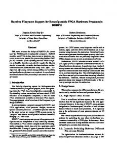
BRAMs and FIF70s Fig. 1. Layout of a small Virtex-4 FPGA (LX15) INTRODUCTION
'1-4244-1488-1/08/$25.00 Q 2008 MEEE. 'IEEE AC paper #1443, Version 4, Updated December 3.,2007. Author's Current Address: The Aerospace Corporation, PO Box 92957, Los Angeles, CA 90009-2957, USA. Based on a presentation at the 2008 Big Sky Conference. 0885/8985/08/ USA $25.00 Q 2008 IEEE
10
Field programmable gate arrays (EPOAs) are quickly becoming the usual targeted technology for many development efforts due to their low cost and rapid development time. Advances in digital technology provide the means to make each generation of FPGAs significantly more attractive and useful than their predecessors. Each generation introduces additional benefits and utilities besides
10 IEEE A&E SYSTEMS MAGAZINE, JULY 2008
Authorized licensed use limited to: University of Florida. Downloaded on December 10, 2008 at 08:27 from IEEE Xplore. Restrictions apply.
Table 1. Summary of Configuration Options Port
Bus
Max.
Table 1. ExampleConfiguration Sizes and Times to Configure with JTAG and SelectMAPIICAP
uSec/Fraine Design
Serial
1 bit
100 MHz
13.12
JTAG
1 bit
66 MHz
19.88
SelectMap
8 bits
100 MHz
1.64
ICAP
8 bits3
100 MHz
1.64
the expected larger size and faster speed. Exploring suitable applications for the latest available products must be a continuous endeavor because their performance and abilities improve significantly with each new product release. Additionally, because each vendor's products have characteristics and utilities that are not necessarily shared by the competition and are often unique, evaluating a specific vendor's product requires significant effort and prevents a straightforward side-by-side comparison. One advancement of significant importance is the ability to reconfigure a portion of an FPGA. This ability is referred to as partial reconfiguration (PR). The focus herein is to evaluate runtime partial reconfiguration in Xilinx's Virtex-4 FPGAs as it applies to the field of software-defined radio. To date, at least three vendors provide products that offer some degree of partial reconfiguration (Xilinx [1], Atmel [2], Lattice [3]). The real advantage of partial reconfiguration occurs when the reconfiguration takes place dynamically during runtime. Runtime partial reconfiguration, or dynamic reconfiguration, allows the reconfiguration of a portion of an FPGA while the remainder continues to run continuously without losing any data. Because partial reconfiguration is coupled very closely to the underlying framework of the FPGA itself, each vendor's FPGAs will have significant differences that may appear as disadvantages or advantages for a given application. Previous work has been done that presents a summnary of the available FPGAs that offer partial reconfiguration [4]. Due to the rapid advancement of the field, the information contained in [4] from 2003 has already become outdated. For example, [4] summarizes the available options for the original Virtex family (the XCV 1000, specifically), which was upgraded in 2002 with the Virtex-II family, which was again upgraded in 2005 with the Virtex-4 family, and has presently been upgraded with the latest Xilinx family, Virtex-5. Each release includes improvements to the existing products and to partial reconfiguration specifically. (This paper explores potential uses of the Virtex-4 devices and makes no claims as to the abilities of future devices from Xilinx or other vendors.) An in-depth
'The ICAP has a 32-bit mode but is believed to function only in the 8-bit mode at the present time.
Turbo Encoder Turbo Decoder
Framnes4
JTAG
SelectMap/ ICAP
154
3.061 ins
0.252 ins
4092
81.34 ins
6.710 ins
5610 SS Acquisition 4752 FFT bins) (8192
111 ins
9.2 ins
94.47 ins
7.79 ins
look at partial reconfiguration can be found in [5], which includes a low-level description of partial reconfiguration in Xilinx's Virtex-JI devices as well as an overview of some of the available tools developed to assist with partial reconfiguration. This paper is organized as follows: the next section gives a very brief overview of software-defined radio; followed by a closer look at partial reconfiguration; next how partial reconfiguration fits with software-defined radio, and finally, the concluding remarks. SOFTWARE-DEFINED RADIO Wireless communication abilities are becoming ubiquitous in the latest generation of portable electronics. Besides the large variety of cellular communication standards, cell phones often come equipped with the capability to connect to wireless ear buds. The latest generations of cameras are even starting to become equipped with various wireless communication options to transfer pictures to and from select devices. All the while, satellites are being launched that employ different modulations and methods for forward error correction. In order to communicate with a wide array of devices, an overwhelming number of communication standards must be available at any given time. Hardware designs that attempt to provide compatibility with the current standards, if even possible, will likely become obsolete shortly after their release. Software-defined radios (SDRs), where the communication parameters are defined at runtime by software, have become increasingly attractive. A collection of readings covering many of the important topics relating to SDRs can be found in [6]. Advancements in FPGAs have made the realization of such SDRs possible [7]. A modem software-defined radio would ideally possess a multitude of function blocks that are available at any given time and must be able to handle the bandwidth of the 'Configuration of a framne requires 41 32-bit words of configuration data.
IEEE A&E SYSTEMS MAGAZINE, JULY 2008
Authorized licensed use limited to: University of Florida. Downloaded on December 10, 2008 at 08:27 from IEEE Xplore. Restrictions apply.
I1I
required channel. Creating a design that contains all possible options at the same time is not feasible. An FPGA's reconfigurable nature, however, provides a good foundation for creating a modular design that can load the desired functions as needed. In particular, reconfiguring the functionality of a specific block while the remainder of the design continues to function provides a unique opportunity to create an extremely flexible and compact design. PARTIAL RECONFIGURATION IN THE VIRTEX-4 Before exploring the potential uses of partial reconfiguration, it is important to be aware of the current performance and limitations of the targeted device. Because of the widespread use of Xilinx's FPGAs, the Virtex-4 family was chosen as the example FPGA. Of major importance are reconfiguration speeds and methods, design hierarchy limitations relating to PR modules (PRMs) and the number of allowed PR regions, and software support for generating PR designs. In order to discuss some of the specifics related to PR, it is important to understand the general structure of the Xilinx FPGA and how it is configured. Each device will have variations to the size and location of various elements, but the overall structure of a Virtex-4 FPGA can be seen in Figure 1, where CLBs are configurable logic blocks, BRAMs are block random access memories, FIFOs are first-in first-out buffers, DCMs are digital clock managers, DSP48s are Xilinx's digital signal processing units, and IOBs are input-output buffers. The FPGA is configured by writing bits to its configuration memory (CM). The configuration data is organized into frames that target specific areas of the FPGA through frame addresses. When using PR, the partial bitstreams will contain configuration data for a whole frame if any portion of that frame is to be reconfigured. Reconfiguration Speed Reconfiguration times will be highly dependent upon the size and organization of the PR region(s). The Virtex-4's predecessor, the Virtex-JI, allows for PR of whole columns only, which potentially requires partial bitstreams to be significantly larger than necessary. Allowing for arbitrarily-shaped PR regions was a great improvement in the Virtex-4 design. Because design size will impact the reconfiguration time, the metric of uSec/Frame is used when calculating the reconfiguration speed. Frames are composed of 41 32-bit words. The smallest Virtex-4 device, the LX15, has 3,740 frames, and the largest device, the FX140, has 41,152 frames [8]. There are four methods of configuring a device: externally through the serial configuration port, the JTAG (Boundary Scan) port, or the SelectMap port, or internally (using an embedded microcontroller or state machine) through the intemnal configuration access port (ICAP). Each of these methods will have applications where they are the most desirable. Because reconfiguration using an embedded microcontroller provides a very flexible and powerful platform for PR designs, the
12
next subsection will present more details relating to this topic. A summary of the configuration speeds is shown in Table 1. To give an idea of approximate configuration times for various PR applications, the estimated sizes of some common blocks and their configuration times are included in Table 2. Note that a certain amount of overhead is involved in setting up the addressing for PR and has been roughly estimated by the author as approximately 10% and has been ignored in all calculations. Also, multiple frames with the same configuration can be written at the same time, thereby shortening the bitstream. The values in Table 2 were based on estimates in Xilinx's PlanAhead software when targeting an approximate PR region slice utilization of 90%. Actual sizes and times will be dependent upon design implementation, target device, region utilization, and resource location. For the examples in Table
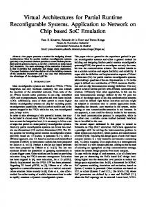
Fig. 2. PR design using embedded microcontroller 2, the turbo encoder and decoder were purchased cores from Turbo Concepts [9], the spread-spectrum (SS) acquisition block was a custom design capable of checking 300 chip offsets and 10 frequency offsets in parallel with variable correlation times up to 100,000 chips, and the fast Fourier transform (FFT) was a Xilinx core with 8192 bins and 12-bit inputs. (It is expected that the configuration port is the bottleneck in determining the reconfiguration times.) Reconfiguration Using an Embedded Microcontroller In addition to supporting an embedded soft processor core (Xilinx's MicroBlaze) in all Virtex-il and later FPGAs, Xilinx also provides several FPGA lines that include embedded IBM PowerPC hard processor cores. The ability of these cores to process C/C++ code makes them an extremely flexible option for reconfigurable designs. By controlling reconfiguration using a processor that is embedded within the FPGA itself, the need to interface with an external controller (such as a PC) can be eliminated, allowing for autonomous operation (depending upon the embedded software design and desired functionality).
12 IEEE A&E SYSTEMS MAGAZINE, JULY 2008
Authorized licensed use limited to: University of Florida. Downloaded on December 10, 2008 at 08:27 from IEEE Xplore. Restrictions apply.
TOP MODULE
a) Hierarchical view before PR partitioning. Fig. 3. Example design showing two PR regions One potential embedded system design is shown in Figure 2. The example design shown in Figure 2 includes C/C++ code that determines when reconfiguration is necessary. When needed, the microprocessor loads the desired configuration data from external memory and reconfigures the PR region through the ICAP primitive. Reconfiguration in this example is expected to be triggered by an event on the FPGA itself, such as acquisition of a PN code, loss of signal lock, detection of an interfering signal, a set timer, etc., but could also be triggered by an external interrupt. The external memory could consist of ROM, Flash memory, or static RAM that is loaded at start-up or even filled by the FPGA itself (in the case where the FPGA is configured as a receiver and receives configuration data as the payload of a transmission). Xilinx. provides extensive embedded microprocessor design support, including reconfiguration support in the form of source code for software functions and hardware implementation code for the peripheral bus interface and necessary processes. The embedded microcontroller can easily be replaced by a custom state machine that handles the loading of configuration data when the overhead of an embedded microcontroller is undesirable. PR Design Hierarchy Because the flow from the Hardware Description Language (HDL) to configuration bitstream is extremely complicated, limitations on design hierarchy exist to assist the software tools in creating PR designs. The primary limitation requires that the top-level module contain submnodules that are either static modules (SMs) or partially reconfigurable modules (PRMs). All communication (with a few exceptions for global signals such as clocks) must be explicitly declared using 8-bit bus macros provided by Xilinx. The current design flow allows for multiple PRMs in a single design. An example design with two PRMs is shown in Figure 3. The required hierarchy adds a significant amount of effort when converting an existing static design into one that is
Fig. 4. Transceiver design with turbo coding and concatenated convolutional + Reed-Solomon Coding ready for PR. Having all the PRMs at the top level will often require routing many signals to and from another module deep within the main static module. For example, a transceiver with FEC modules embedded deep within both the transmit and receive portions of the design requires routing all the necessary signals up and down through the entire hierarchy in order to have partially reconfigurable FEC modules. This example is shown in Figure 4, where the original unpartitioned design is shown in Figure 4A, with the partitioned design shown in Figure 4B. PR Software Support When PR initially became available, there was very little software support to assist in generating PR designs and bitstreams. Efforts within the academic community attempted to ease the burden of designers wishing to employ PR and accomplished a limited amount of automation [10, 11]. Recently, Xilinx has released an Early Access design flow for PR that integrates with their sophisticated floor-planner tool, PlanAhead, and their synthesis tool, ISE. Modifications are made to the ISE tool, making it valid only for PR designs such that PlanAhead can call the modified functions in an automated command-line fashion, hiding the user from many
IEEE A&E SYSTEMS MAGAZINE, JULY 2008
Authorized licensed use limited to: University of Florida. Downloaded on December 10, 2008 at 08:27 from IEEE Xplore. Restrictions apply.
113
of the low-level details that were previously the responsibility of the user. When determining the size and location of a PR region, PlanAhead provides statistics on the required primitives (DSP48s, BRAMs, etc.), the available resources in the defined area, and statistics on utilization that greatly help during the floor-planning stage. PlanAhead also comes with a design-rule checker that assists in correcting any violations due to placement. While the PR flow's integration into PlanAhead continues to become more user-friendly with each release, the present software support makes PR designs manageable. As PR becomes mainstream, it is expected that Xilinx and other FPGA vendors will more fully support this technology through improved tools and documentation.
Fig. 5. Simplex transceiver with spread-spectrum and FEC
SDR AND PARTIAL RECONFIGURATION Determiining whether PR is appropriate for a given application depends heavily upon the FPGA family, the application details, and the application environment. However, partial reconfiguration (PR) has moved beyond being an emerging technology where the majority of efforts have been for research only to a viable option for product development. As such, one field where it can be applied to great advantage is software-defined radio. Simplex Spread-Spectrum Transceiver with FEC One potential SDR use would be in a simplex transceiver, where only transmit or receive capabilities are used at any given time and are never used at the same time. Assuming that the waveform requires FEC as well as direct-sequence spread-spectrum (DSSS), the design could be organized as shown in Figure 5. Two PR regions are declared: one for either the Tx modulator or the Rx demodulator, one for the Tx FEC encoder, the Rx DSSS acquisition engine, or the Rx FEC decoder. DSSS acquisition typically requires a lot of resources but is used only during the acquisition phase. Once the spreading code has been acquired, those resources can be reconfigured as the FEC decoder while the Rx demodulator continues to track the spreading code. Dynamic Bandwidth Resource Allocation Transceiver Systems employing dynamic bandwidth resource allocation (DBRA) would benefit substantially from the use of PR. These systems alter the communication waveform dynamically to match channel conditions. For instance, if the signal-to-noise ratio (SNR) drops such that an unacceptable hit-error rate (HER) occurs, a combination of modulation type, data rate, or FEC configuration changes may be performed to decrease the BER. Alternately, if a high SNR is detected, reconfiguration could be used to increase throughput while still maintaining the desired BER. Figure 6 shows one possible scenario with a transceiver employing DBRA where the Tx waveform changes from turbo-coded binary phase shift-keying (BPSK) to Gaussian minimum shift-keying (GMSK) with a concatenated
14
Fig. 6. Dynamic bandwidth resource allocation transceiver
Channelizer( FFT
Fig. 7. Cognitive radio receiver convolutional encoder, followed by Reed-Solomon (RS) encoding. The Rx waveform switches from turbo-coded BPSK to 8-ary phase shift-keying (8PSK) to the concatenated Viterbi and Reed-Solomon decoder. Cognitive Radio Another example for the use of PR in SDR applications comes in the field of cognitive radio (CR). A CR receiver
14 IEEE AESS SYSTEMS MAGAZINE, JULY 2008
Authorized licensed use limited to: University of Florida. Downloaded on December 10, 2008 at 08:27 from IEEE Xplore. Restrictions apply.
CONCLUSIONS
Funion3Z SoftwareDefined Radio on PC
ZunionU2 FntonE]
Fast External Memory (-I GB)
Fig. 8. Hardware acceleration of software-defuined radio must scan the available spectrum using an FFT, locate energy, create a channel that attempts to match the spectral shape, perform modulation recognition, and then try to demodulate. Because the spectrum must always (or at least very often) be monitored, the FFT module is left as static, but use of the modulation recognition and demodulator are mutually exclusive, providing an opportunity to take advantage of PR. It is expected that switching between modulation recognition and demodulation will occur often as the receiver searches the available signals for the correct one. If reconfiguration could be achieved quickly enough, the FF1' module could potentially be made reconfigurable as well. Partitioning for this CR receiver example can be seen in Figure 7. Hardware Acceleration (Future Work) While much research has been done in the field of hardware acceleration, including the application of PR to this field, it is still worth illustrating how PR can be applied to this problem. Considering a fully software-defined radio receiver, it is clear that certain functions exceed the throughput of even the most powerful general purpose processor (GPP). Situations where the hardware can greatly reduce the throughput - such as decimation and despreadinghave obvious benefits. Additionally, many of the latest FEC codes are computationally intensive, making them untenable for software-only receivers. If some latency is acceptable and enough memory exists, it is possible to implement a multichannel receiver in software while buffering data and time-sharing the FPGA as necessary to process the data when necessary. Using an embedded microprocessor and a memory manager, portions of the FPGA could be partially reconfigured (similar to a context switch) to process one channel's data and then reconfigured to process another channel's data. Because the data can be buffered during the reconfiguration, the only limitation is the average throughput of the FPGA, assuming that the memory is sufficiently deep to avoid any losses during reconfiguration and buffering. Figure 8 shows a block diagram of such a system.
Exploring the usefulness of PR in the field of software-defined radio has shown both its feasibility and benefit. Several potential uses were detailed to illustrate how one might take advantage of this emerging technology. Resource utilization for a select number of function blocks were shown along with the required reconfiguration times. The latest software from Xilinx was found to relieve the user from the burden of following a complex design methodology when creating PR designs. The design time overhead involved when creating a PR design is acceptable but requires progressing through a slow learning curve before any results can be obtained. Much of the necessary support will likely come from the PR community and not necessarily from the vendor. The full benefits of PR will not be evident until it becomes commonplace in industry and the vendors place more resources on supporting the PR design flow and keeping the tools and documentation up to date. However, the adaptivity of PR combined with the desire for software-defined radios makes a strong argument for pursuing partial reconfiguration. FXERENCES [1] Xilinx Virtex-4 Users Guide, www.xilinx.com. [2] Atmel AT40KAL Users Guide, www.atmel.com. [3] LatticeXP Family Data Sheet, www.latticesemni.comn. [4] S. Donthi and R.L. Haggard, A survey of dynamically reconfigurable FPGA devices, in Proc. of the 35* Southeastern Symposium on System Theory, Cookeville, TN, March 16-18, 2003.
[51 D. Mesquita, F. Moraes, J. Palma, L. Mailer and N. Calazans, Remote and partial reconfiguration of FPGAs: tools and trends, in Proc. of the International Parallel and Distributed Processing Symposium, April 22-26, 2003. [6] Z. Zvonar and J. Mitola, Software Radio Technologies, May 2001, Wiley-IEEE Press. [7] E. Grayver and P. Dafesh, Multi-modulation programmable transceiver system with turbo coding, in Proc. of the IEEE Aerospace Conference, Big Sky, MT. March 5-12, 2005. [8] Xilinx Virtex-4 Configuration Guide, www.xilinx.com.. [9] www.turboconcept.com. [10] P. .lames-Roxby and S.A. Guccione, Automated extraction of run-time parameterisable cores from programmable device configurations, in Proc. of the IEEE Symposium on Field-Programmable Custom Computing Machines, Napa Valley, CA, April 17-19, 2000. [11] E. Horta, J.W. Lockwood, D.E. Taylor and D. Parlour, Dynamic hardware plugins in an FPGA with partial run-time reconfiguration, in Proc. of the Design Automation Conference, June 10-14,2002.
IEEE A&E SYSTEMS MAGAZINE, JULY 2008
Authorized licensed use limited to: University of Florida. Downloaded on December 10, 2008 at 08:27 from IEEE Xplore. Restrictions apply.
A
115