CMOS APS IMAGER EMPLOYING 3.3V 12 BIT 6.3 MS/S PIPELINED ADC Shy Hamami, Leonid Fleshel and Orly Yadid-Pecht The VLSI Systems Center, Ben-Gurion University, Beer-Sheva, Israel, e-mail:
[email protected] ABSTRACT A novel 256x256 CMOS active pixel sensor (APS) system with 12 bit, 6.3 MSample/s (MS/s) CMOS pipelined analog to digital converter (ADC) integrated on chip is presented. The test chip has been implemented in 0.35µm 2P4M process, operated by a 3.3V supply and is expected to dissipate 55mW. The total area of the prototype is 12 mm2, and the core area of ADC is 18% from the total area. System architecture and operation are discussed and simulation results are presented.
integrated on the same chip. The test chip has been implemented in 0.35µm 2P4M process, operated by a 3.3V supply and at conversion rate of 6.3 MS/s is expected to dissipate 55mW. This work is arranged as follows: Section II addresses the system architecture. Section III presents the circuit implementation. Section IV describes the measured results. A summary concludes the paper.
2. SYSTEM ARCHITECTURE 2.1 APS Architecture
Row Driver
Row Decoder
Driven by the demands of multimedia applications, digital cameras rapidly became attractive. The basic requirements of digital cameras, in addition to image capture must include analog-to-digital conversion and digital signal processing. CMOS technology is rapidly scaling down, enabling integration of these functions onto a single chip [1,2,3]. Integration of a CMOS sensor with an ADCs can be done in three fundamental approaches: • Pixel level approach [4,5]- A separate ADC is allocated for every pixel. • Column parallel approach [6,7,8]- Each ADC serves one or more columns in the sensor array. • Chip level approach [9,10]- A single ADC serves the whole image sensor. Different kinds of ADCs can be integrated with APS imagers, but only a few of them can meet requirements of the chip level approach at video rate. The best options for low power implementation in 5 MS/s sampling rate (and above) and at resolution of 8-12 bit range, are multi-step flash and pipeline configurations. In comparison to multi-step flash, a pipelined ADC has the potential advantages of inherent signal single-path sampling, which gives good high-frequency effective bit performance. In addition, signal amplification down the pipeline followed by digital error correction relaxes the comparator offset constraints, which enables the usage of dynamic comparators. Pipelined ADC has been the subject of investigation during last several years [11,12,13,14]. Recently, a 10 bit, 1.8 V, 65mW, 50MS/s [15], and a 12 bit, 3V, 35mW, 21MS/s CMOS pipelined ADCs [16] have been reported. The advantages of the pipelined ADC, which combines high speed with medium-high resolution and low power consumption seems a promising combination with the standard CMOS APS implementation. This paper presents a novel 256x256 CMOS APS system with 12 bit, 6.3 MS/s CMOS pipelined ADC
Row
1. INTRODUCTION
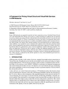
The architecture of the sensor is shown in Figure 1. As in a traditional rolling shutter APS the proposed sensor has an imager of 256x256, 3 transistors (3T) pixel array, row decoder, row driver, column decoder Sample & Hold (S/H) circuits, clock and signals generator, timing block, and a 12 bit pipelined ADC.
Timing and Control Column Block
Pixel
Pixel
Pixel
Pixel
S/H
Output Chain
Column Decoder Clock and Signal Generator
x1
Pipelined ADC 12
Figure 1: The sensor architecture The single pixel with an N-well photodiode has a fill factor (FF) of 12% and a pitch of 7µm. The operation principle is described in [3] and will be briefly summarized here. The pixel consists of a photodiode reset transistor (RST) and a row select transistor (RS). The charge-to-voltage conversion occurs at the sense node capacitance, which consists of the photodiode capacitance and all other parasitic capacitances connected to that node. The source-follower transistor (SF) acts as a buffer amplifier to isolate the sensing node. When a reset pulse is applied, the photodiode is charged to a known value limited by the threshold voltage of the RST transistor. The integration starts when the RST transistor is switched off. During integration, the photodiode discharges the capacitance of the photodiode node. Finally the value is read out through the SF and the RS. The S/H circuit has to convert the single ended
2
COL1
Vref+
Vref-
COL1
1
CS
CS
COL1
SHR '
SHS '
Buffer
CF
S/H Circuit
VCM
SHR SHS
φ1
S/H Circuit
VCM
Pixel Out
.
COL1 S/H Circuit
φ1 φ1 φ 1 OpAmp φ 1
Vout-
STAGE 2
STAGE 3
2 bit
2 bit
2 bit
L
STAGE 11 2 bit
DIGITAL ERROR CORRECTION
CF
v − v sig ) − vref C F ( rst
[1]
A detailed op-amp topology is discussed in section 3.
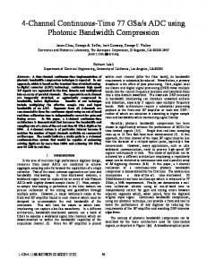
2.2 Pipelined ADC Architecture The ADC uses a pipeline 1.5-bit/stage architecture [11] with 11 stages, as shown in Figure 3. Each stage is responsible for resolving two bits from the digital output code. Each stage is composed of a coarse Flash-ADC, a low resolution digital to analog converter (DAC), a S/H circuit, and a residue amplifier. The 2-bit MSB low-resolution ADC determines the two MSBs. The determination of the remaining LSBs is performed in the following steps: (1) The quantization error is found by reconverting the 2-bit digital to an analog value using the 2-bit DAC. (2) This value is subtracted from the input signal, generating a residue. This residue is then amplified by a gain of two and passed on to the next stage. The second stage performs similar operations on the amplified residue resulting in a determination of the next most significant bits of the input signal. The stages are buffered by switching-capacitors gain blocks that provide a S/H between each stage, allowing concurrent processing. Digital error correction [11,12] is used to generate the 12 bit final output code from the resulting 22 bit. The use of a digital error correction technique in conjunction with a low number of bits per stage relaxes the constraints on the comparator offset voltage. Figure 4 displays the pipelined ADC stage implementation. Although, a single-ended configuration is shown for simplicity, the actual implementation was fully differential. The pipelined ADC stage consists of (1) Two comparators
ADC
×2
Residue
12 bit
pixel output into a differential mode, since the pipelined ADC was implemented in a fully differential configuration. Figure 2 exhibits the output chain block diagram, which consists of a S/H circuits and a buffer. The clocks Φ1 and Φ2 are non-overlapping and are used for the pipeline timing (Φ2 is not displayed in Figure 2). The signal COL1 is a result of a logical AND between the column decoder output and Φ2. The design (i.e., both the S/H circuit and the pipelined ADC) utilizes a bottom plate sampling technique (i.e., SHS' and SHR'), thus eliminating the first order signaldependent charge injection distortion. In addition, slow SHS and SHR are applied to minimize charge injection and clock feed-through offsets. 1pF sampling and feedback capacitors, CS and CF respectively, are used in order to reduce the kT/C noise. The output chain transfer function is given by:
∑
S/H
Analog Input
Figure 2: Output chain block diagram
vout =
STAGE 1
Vout+
φ1
CS
Analog Input
VCM
..
256
DAC
2 bit
Figure 3: The selected pipelined ADC architecture
CF
Vin
CS `
Latch
V + ref 4 `
−
Vref
VO
Mux
− Vref + Vref Latch
4 Coarse -ADC
DAC
Residue GAIN Stage
Figure 4: Pipelined ADC stage block diagram with corresponding threshold voltages Vref/4 and -Vref/4, which, in fact, assemble the coarse Flash-ADC, (2) An analog mux that actually functions as DAC, with the three corresponding reference voltages -Vref, 0, and Vref and (3) Residue gain stage [14]. The residue gain stage, shown in Figure 5, samples the signal input, subtracts it from the relevant reference voltage, and amplifies the residue by the gain of two. When defining CF=CS, the ideal stage operation is as follows: Vref if Vi > Vref / 4 d → 2 (10 )2 2 Vi − 2 Vo = 2Vi if − Vref / 4 < Vi < Vref / 4 d → 2 ( 01)2 2 V + Vref if V < −V / 4 d → 1( 00 )2 i ref 2 i
[2]
where d is the stage digital output code. Figure 6 shows the ideal transfer characteristics of a pipelined ADC stage. With the use of a digital correction algorithm the overflow of the current stage output from the input range of the following stage can be prevented even with the presence of a large comparator offset, so that this offset error amplified down the pipeline can be detected for correction. With this configuration, the coarse Flash-ADC error, up to Vref/4, can be tolerated and digital correction circuit contains adders only. The correction is achieved by adding the output codes of the pipeline stages in overlapping the stage i LSB with stage i+1 MSB.
VrefVin-
φ
1
φ2 φ2
CF
CS CS
φ1
VCM
Vref+
2
φ1 ' φ1 '
OpAmp
φ1 φ1
Vout-
VCM
Vin+
φ1
φ
Vout+
CF
φ2
φ 1'
t[nsec]
φ2
t[nsec]
t[nsec]
φ 2'
t[nsec]
Figure 7: The non-overlapping multiphase clock waveforms implemented
Figure 5: The residue gain stage
VDD CMFB
Vout
00
01
+Vref
VDD
10 VDD
Vo2
VDD
VDD
Vin1 +Vref Vin
-Vref
-Vref
Figure 6: Ideal transfer characteristics of the pipelined ADC stage The clock timing generator generates non-overlapping multiphase clocks, shown in Figure 7.
3. PIPELINED ADC-CIRCUIT DESCRIPTION Because of the large dc gain requirement in the high resolution pipeline, and in order to achieve a large voltage swing, a twostage amplifier is used for this application. The op-amp topology [13] used in the pipeline stages is shown in Figure 8. This two-stage, fully-differential amplifier consists of a folded cascode first stage followed by a common-source second stage with compensation to the cascode node [17]. The fully differential architecture, although improving power supply rejection, requires a common mode feedback as shown. This extra circuitry is needed to establish a common-mode output voltage. The S/H op-amp is the most critical part in the overall design, because it has to settle within at least 13 bit accuracy in one clock phase. Actually, this settling time limits the overall pipeline throughput. Based on BSIM 3v3 simulations, the settling time of the op-amp is less than 70nsec for 13 bit accuracy. The op-amp dc gain is 120dB and its phase margin is 63o. The power dissipation of the op-amp including its bias circuit is less than 2.6 mW. There are a total of ten op-amps in the ADC, since the last stage does not need to generate any analog signal. The comparator circuit consists of a preamplifier followed by a dynamic latche circuit and buffer [14]. This architecture improves metastability and reduces kick-back noise on the input residue. The pipelined ADC consists of 22 comparators, which dissipate approximately 4.4mW. The interstage capacitor sizes are determined by the kT/C thermal noise constraints. Due to
Vo1
Vo1 VDD
Vin2 Cc
Cc
Vo2
Figure 8: Operational amplifier architecture relaxed accuracy constraints in later pipeline stages, these capacitors were scaled down to help reduce power consumption [12]. To maximize the matching between the capacitors and minimize bottom plate parasitics, the common-centroid capacitor arrays with dummy capacitors surrounding the arrays are used.
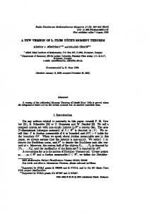
4. SIMULATION RESULTS Figure 9 shows the layout of the test chip. The total area of the prototype is 12 mm2, and the core area of the ADC is 18% from the total area. The test chip has been implemented in 0.35µm 2P4M process, operated by a 3.3V supply. Design simulation has been carried out in SpectreS with BSIM3V3 models of a TSMC 0.35µm 2P4M process. Based on SpectreS simulation, the approximate total power consumption is 55mW. Based on layout extraction, the transient response of the S/H op-amp shows that the maximum settling time to 13 bit accuracy is in 70ns. The chip attributes summary shown in Table I.
4. CONCLUSIONS The trend toward integration is driven by low cost, and low power implementations. Therefore, for video rate applications, integration of an APS system with a chip-level pipelined ADC appears as a very reasonable option. This work successfully demonstrates a novel 256x256 CMOS APS system with 3.3V, 12 bits, 6.3 MS/s CMOS pipelined ADC integrated on the same chip. This experimental chip has been implemented in a 0.35µm 2P4M process, operated by a 3.3V and at conversion rate of 6.3 MS/s dissipates 55mW.
Figure 9: Test chip layout Power Supply Technology APS array resolution Pixel pitch Fill factor ADC resolution ADC conversion rate ADC input range Die area Power dissipation Table 1: chip attributes
3.3 V 0.35µm 2P4M CMOS 256x256 7µm 12% 12 bit 6.3 MS/s ±1 V differential 12 mm2 55 mW
ACKNOWLEDGMENTS The authors acknowledge the financial support of the Israeli Ministry of Defense and Mr. Shai Diller for helpful assistance and discussion. The fabrication was carried out through MOSIS.
REFERENCES [1] E. Fossum, “CMOS Image Sensors: Electronic Camera-onA-Chip,” IEEE Trans. Electron Devices, vol. 44, pp. 16891698, Oct 1997. [2] O. Yadid-Pecht, R. Ginosar and Y. Shacham-Diamand, “A random access photodiode array for intelligent image capture,” IEEE Trans. Electron Devices, vol. 38, no. 8, pp. 1772 - 1781, Aug.1991. [3] S. Mendis, S. Kemeny, R Gee, B. Pain, C. Staller, Q. Kim and E. Fossum, “CMOS active pixel image sensors for highly integrated imaging systems,” IEEE J. Solid State Circuits, vol. 32, pp. 187-197, Feb. 1997. [4] D.X.D. Yang, A. El Gamal, B. Fowler and H. Tian, “A 640x512 CMOS Image Sensor with Ultra Wide Dynamic Range Floating Point Pixel Level ADC,” IEEE ISSCC, WA 17.5, 1999. [5] B. Pain, S. Mendis, R. Scober, R. Nixon, and E. Fossum, "Low-power low-noise analog circuits for on-focal-plane signal
processing of infrared sensors," IEEE Workshop on Charge Coupled Devices and Advanced Image Sensors, June, 1995. [6] A. Dickinson, S. Mendis, D. Inglis, K. Azadet, and E. Fossum, "CMOS Digital Camera with Parallel Analog-to Digital Conversion Architecture," IEEE Workshop on Charge Coupled Devices and Advanced Image Sensors, April, 1995. [7] S. Decker, R. McGrath, K. Brehmer, and C. Soldini, "A 256x256 CMOS imaging arrays with wide dynamic range pixels and column-parallel digital output," ISSCC Digest of Technical Papers, pp. 176-177, February, 1998. [8] A. Krymski and N. Tu, "A 9-V/Lux-s 5000-Frames/s 512x512 CMOS Sensor," IEEE Trans. Electron Devices, vol. 50 pp. 136-143, Jan. 2003. [9] S. Smith, J.Hurwitz, M. Torrie, D. Baxter, A. Holmes, M.Panaghiston, R. Henderson, A. Murray, S. Anderson, and P. Denyer, "A single-chip 306x244-pixel CMOS NTSC video camera," ISSCC Digest of Technical Papers, pp. 170-171, February 1998. [10] M. Loinaz, K. Singh, A. Blanksby, D. Inglis, K. Azadet, and B. Acland," A 200mW 3.3V CMOS color camera IC producing 352x288 24b Video at 30frames/s," ISSCC Digest of Technical Papers, pp 186-169, February 1998. [11] S.H. Lewis; H.S. Fetterman, G.F. Jr. Gross; R. Ramachandran, T.R. Viswanathan; and T. R. Viswanathan, “10-b 20-Msample/s analog-to-digital converter,” IEEE J. Solid-State Circuits, vol. 27, pp.351-358, March 1992. [12] T. Cho, and P. R. Gray, "A 10b 20MSamples/s 35mW Pipeline A/D Converter," IEEE J. Solid-State Circuits, vol. 30, pp. 166-172, March 1995. [13] D. Cline, and P. Gray, “A Power Optimized 13 b 5 MSample/s Pipelined Analog-to-Digital Converter in 1.2µm CMOS,” IEEE J. Solid-State Circuits, vol. 31, no. 3, pp. 443452, March 1996. [14] A. Abo, and P. R. Gray, "A 1.5-V, 10-bit, 14.3-MS/s CMOS Pipeline Analog-to-Digital Converter," IEEE J. SolidState Circuits, vol. 34, no. 5, pp. 599-606, May 1999. [15] S. Hamedi-Hagh, and C.A.T. Salama, "A 10 bit, 50 MSample/s, Low Power Pipelined A/D Converter for Cable Modem Applications," IEEE ISCAS, vol. 1, pp. 424 -427, May 2001. [16] S. Kulhalli, V. Penkota, and R. Asv, "A 30mW 12b 21MSample/s Pipelined CMOS ADC," IEEE ISSCC, vol: 1, pp. 312 -469, February 2002. [17] B. K. Ahuja, "An improved Frequency Compensation Technique for CMOS Operational Amplifier," IEEE J. SolidState Circuits, vol. SC-18, no. 6, pp. 629-633, December 1983.