AbstractâMany communication systems are bandwidth- expanding: the transmitted signal occupies a bandwidth larger than the symbol rate. The sampling ...
Sampling of Communication Systems with Bandwidth Expansion �
Julius Kusuma , Andrea Ridolfi and Martin Vetterli
Abstract— Many communication systems are bandwidthexpanding: the transmitted signal occupies a bandwidth larger than the symbol rate. The sampling theorems of Kotelnikov, Shannon, Nyquist et al. [1] shows that in order to represent a bandlimited signal, it is necessary to sample at what is popularly referred to as the Shannon or Nyquist rate. However, in many systems, the required sampling rate is very high and expensive to implement. In this work we show that it is possible to get suboptimal performance by sampling close to the symbol rate of the signal, using well-studied algorithmic components. This work is based on recent results on sampling for some classes of nonbandlimited signals [2]. In the present paper, we extend these sampling results to the case when there is noise. In our exposition, we use Ultra Wideband (UWB) signals as an example of how our framework can be applied.
I. I NTRODUCTION A communication system sends messages from the transmitter to the receiver by having the message bits select symbols from a finite set called a constellation, and then transmitting the selected symbol through a channel after properly modulating them. Modulation refers to translating the symbols into signals that can be sent through the channel of interest. This motivates us to consider communication in the following light: The transmit pulse is a “deterministic” component of communication, and the message is conveyed in the selection of symbols. Taking advantage of linearity and time-invariance of the pulse shape, we can write the baseband signal as a stream of deltas with amplitude and delay chosen by the message bits convolved with the transmit pulse. This constitutes a large class of communication systems. In recent work [2], Vetterli et al. showed a generalized view of sampling. Recall the sampling theorem for bandlimited signals, due to Kotelnikov, Shannon, et ����� that is banal. [1]. The main result is that a signal � dlimited to ����, �� can be sufficiently represented by its sam� � ples ��
�� taken every ����� as follows: �
�����
�
���
�� � �
�
�����!�
sinc
��� �
�#"$� �&%
�('*)
(1)
1 Department of EECS, University of California at Berkeley, and ´ 2 LCAV, Ecole Polytechnique F´ed´erale de Lausanne, Switzerland
�����
�10����
�� �
0��
,+�-/. � where sinc is the sinc function. In the case of a non-bandlimited signal, such a sampling theory can only apply to the lowpass approximation of the signal. That means to first lowpass filter the signal and then to sample it at the appropriate rate. Of course, the obtained samples are a sufficient representation of the lowpass approximation of the signal and not of the signal����itself. We � refer to the lowpass filter as the kernel filter 2 . In [2] it is shown that it is possible to completely reconstruct a signal that is not bandlimited from uniform samples of its lowpass approximation, provided that the signal has a finite rate of innovation. The rate of innovation is defined as the number of degrees of freedom per unit time. In terms of a model based representation of a signal, the number of degrees of freedom (per unit time) can be seen as the number of parameters (per unit time) required to model the signal. Then, the reconstruction is possible provided that the lowpass approximation has ����� and been obtained with the appropriate kernel filter 2 that the samples have been taken at rates above the rate of innovation. Such a sampling model is shown in Fig. 1.
Sampling model: 3547698 is the signal, :;47698 is the kernel filter, = 476�?A@�BC8 is the sampling operator, DFEG47698 is the sampled signal
Fig. 1. and D
are the samples.
An excellent example is a signal that consists of a finite stream of weighted Diracs: �
�����
IH
�J
� ��KML
JON
J ���P"$�
�&%
�Q'*) J
(2)
JTS J %��
�
This signal itself is fully specified by R ��K , which H L are the amplitudes and locations of the Diracs respectively. Hence, we can see that the signal has UOV degrees of freedom and, following [2], it is fully characterized by the samples of its lowpass approximation. However, the traditional view of sampling suggests that it is impossible to perfectly reconstruct the signal from a finite number of (uniform) samples, because it has infinite bandwidth. In a communication context, the rate of innovation of a memoryless modulation system is the symbol rate. From here on we will use this term. In many wideband communication systems, according to the classical sampling theory, the large signal band-
width prescribes a prohibitively high sampling rate to implement an optimal matched filter receiver. For example, Ultra Wideband can use bandwidths of up to several hundred megahertz. Sampling at the symbol rate can be a solution to such a problem. Indeed, we will show that it is possible to reliably decode a received signal by sampling it at the symbol rate, not at the sampling rate dictated by the bandwidth of the transmit signal. II. S AMPLING
AT THE
R ATE
OF I NNOVATION
We now present a review of [2], specifically for two classes of signals that are of interest in this work: 1) A stream of Diracs. 2) A stream of pulses of a deterministic shape. A. Sampling a Stream of Diracs We repeat one of the main sampling results in [2]. Let � be a -periodic stream of V Diracs (2). Then, we can perfectly reconstruct the signal from �samples that have been uniformly taken with a period ����,� such that � a lowpass �� UOV I� , using as sampling kernel 2 " 0 � % 0 � � V � filter with bandwidth V . The key insight here is to observe that for the given ����� , the Fourier series is: � �����
�� ��
��
� � �
�
�
�
H
� � � � ���� �� ���� ��
� � �� ������ �� J�
�
��K
�
�����
�
�
J
�
%
'
(3)
��K L
� � � �� ��
From the above expression we ' can straightforwardly see that the coefficients , , contain complex V J JTS J UOV �� coefficients exponentials. Therefore, , " % �% %�� � V V are sufficient to calculate R ��K . Those H UOV � coefficients are the ones still L available after the lowpass filtering process and they can be easily computed by taking at least UOV � samples of the filtered signal. � Fourier coefficients, several Once we have the UOV classical approaches can be used to retrieve the Diracs. Indeed, from a model based approach point of view, the estimation of a stream of Diracs can be seen as the dual problem of the classical line spectra estimation. Therefore, estimation of the Diracs can be achieved by adapting one of the well developed parametric J methods for line specS J tra [3]. The difficult step of such� methods is commonly J S J � the estimation of the positions R ��K while, knowing � H the positions, the weights R ��K are easily obtained by H solving a linear system. L In [2], the positions are retrieved using an annihilating filter based method. Such a method, which is a first order
!!! "�
��
#�
� � �
method, has revealed a poor noise robustness. Second order methods, such as ESPRIT [4] or MUSIC [5], present a better noise robustness. They are also commonly known as covariance methods. We can also extend this sampling result to the nonperiodic case, using the same key idea. ����� One thing to note is that the sampling kernel 2 can be any lowpass or bandpass filter of the appropriate bandwidth since we only require to take a sufficient number of contiguous samples in frequency. B. Sampling a Stream of Pulses The extension of the previous results to a stream of pulses is straightforward. Indeed, we can write a stream of pulses with deterministic shape as a stream of Diracs convolved with the pulse shape and, provided that we know the spectra of the pulse shape exactly, we can invert the effect of the pulse shape on the Fourier representation at the band of interest. We refer to such an inversion operation as equalization, as it is commonly denoted in a communication systems context. III. S AMPLING I NTERPRETATION C OMMUNICATION
OF
In this section we further our exploration of the application of the new sampling idea to communication systems. We will develop our framework on a specific example of a bandwidth-expanding communication system, namely Ultra Wideband communication. The idea is to consider the Diracs as the carrier of information. Ultra Wideband (UWB) has gained popularity, mostly targeted towards short-range low-power communication. The idea here is to use very low duty-cycle signaling by either PAM or PPM. Unfortunately, to the best of our knowledge, at the present very little is known about how to practically and efficiently implement UWB systems. In our example we consider the PPM system, but note that it is easy to extend the framework to PAM systems. The framework that we have discussed in Subsections II-A and II-B enables us to see that it is sufficient to recover the signal by sampling at the innovation rate, which in this case is the symbol rate. In our treatment we explored the case when the signal of interest is a stream of pulses. A. The Compound Channel The “pulse shaping effect” on the received signal is due to both the transmit pulse shape and the channel. In many scenarios, the channel of interest is linear (and possibly
time-varying), and for small time intervals can be ��mod��� eled by an linear time-invariant (LTI) system. Let be � ����� ����� the pulse shape and the ima stream of Diracs, pulse response of the channel. Then, the received signal ����� � is given by
|X(w)|
�
�
�
� �� �� �����
�����
��
�
�����
�������&% �
�('*)
�
�� ��
��
�
By this viewpoint we consider the compound channel shown in Fig. 2.
0
T
2T
3T
Compound channel
t
t
Fig. 2. Illustration of the compound channel
�� �� �
Moreover, we have to take into account the presence of ����� an addictive white noise . Finally, we have �
�
�����
�����
�
�����
���
�����&%
�Q'*)
(4)
Recall that we need to first identify the LTI component of our compound channel: consistently with our previous treatment of convolved Diracs, an equalization must be performed. Therefore, our scheme requires channel identification. B. Bandpass Approximation for Receivers ����� As already mentioned, the sampling kernel 2 can be any lowpass or bandpass filter of the appropriate bandwidth. We are interested in bandwidth-expanding communication systems, and because the innovation rate is lower than the signal bandwidth, we get a degree of freedom in choosing the bandwidth over which we take our samples, i.e. the bandwidth of the sampling kernel used for the bandlimited approximation of the received noisy signal. It is easy to see that the best choice is the band with the highest signal power, and SNR. We show this in Fig. 3. More precisely, let us consider the classical bandlimited SNR formula:
����� �� � � �� �� � � �� ���� � �� � � � � � �� �� � � � � ��� �
�
�
�
�
�
�
�
�
� M� �
����� �� � � �� �� � � ��� � �
� � �
�
� M� �
�
�
where we have taken advantage of the whiteness of the noise. From this equation, it follows that the position of the band K can be chosen so to maximize the SNR. In particular, by considering that a UWB signal, even in its baseband form, has a zero DC component in order not to overheat the amplifiers, we obtain a bandpass sampling kernel.
�
C. Canonical Wideband Receiver Because the UWB pulse is very similar to delta functions, it is an ideal candidate for the new sampling scheme. It requires minimal amount of equalization, except for the notch at DC. However, we now know that we can apply bandpass approximation over our band of interest.
Received signal
Encoded message
w Lowpass approximation Bandpass approximation
Fig. 3. Illustration of picking the best band to maximize SNR
We will jointly consider the effect of these element by referring to them as the compound channel. In practice, the compound channel also compensate for the receiver frontend effects, and in particular for the fact that the����bandpass � approximation is not perfect. If we denote by the corresponding impulse response, the previous equation becomes ����� ����� �����&% �Q'*) �
No
� M� �
�
UWB Receiver Algorithm: Sampling of single-user signal
received signal of eq. (4) and � be�� the noisy its bandpass approximation. ��� samples � of � ; 1) Take � 2) Calculate the spectra � ��� ; 3) Calculate � ��� � ; spectra of the “pulse shaping effect” � � � ��� � ; 4) Equalize: ! ��� "� ��� 5) Estimate amplitudes, locations of Diracs from # . In the above� algorithm,$� the spectral quantities are com� which � puted over � represents the � band of interest, � is� an oversampling rate that we have introduced, and ��� can � be. seen as the freq. response of the compound channel �
�
Let �����
�
�����
�
�����
�����
2
�����
UOV
�
K
"
�OU
%
K
�OU
�����
Note that a departure from what was presented in [2] is that in this case we use passband approximation instead of lowpass approximation. Therefore we use sam����� � �!� � ��� plingJ kernel 2 sinc K instead of its S JTS lowpass equivalent. How does this effect our estimation � of R and J R S ? J L Using passband approximation does not effect our es� � . To see this, note that the terms creates timate of R the complex frequency in the Fourier domain. Passband approximation equals shifting in the Fourier domain, and complex frequency is indifferent to sample shifting.
&%('*) ,+��
Fig. 4. UWB PPM Receiver J S
Using passband approximation effects the estimate of J R . This� is� easily resolved by J multiplying the results by J � " L K . We are basically solving a slightly� different system of linear equation for for our given , due to L our new sampling kernel. We show the new PPM receiver in Fig. 4. Concerning the estimation of the locations of the Diracs, the requirement of noise robustness naturally lead to the choice of a second order method. In particular we consider the ESPRIT method [4]. As already discussed, the amplitudes are then obtained through the solution of a linear system. The complexity of the system is set by several computationally intensive operations:
%('*) +��
error rate
�
2
! ��� �
� �
�
� ��� ����� �
� � �
� �
� ���
� � � ���������
All these steps are done once per symbol.QAs a function � � of , the complexity grows as . Oversampling improves the estimate of the covariance matrix, and thus improves the performance of the system, as has been studied in the frequency estimation literature. We show the tradeoff of performance versus oversampling in Fig. 5 and complexity versus oversampling in Fig. 6 for different SNRs.
4
8
16
oversampling
Fig. 5. Error rate versus oversampling
Complexity vs. oversampling rate 80
70
60
growth of complexity
� �
−1
10
5 dB 10 dB 15 dB
� ������� �
1) FFT to get the frequency-domain samples. Com� (� V . plexity is of order V 2) Equalizer to invert the effect of the pulse shape, channel, and frontend imperfections. It includes � (� divisions. V 3) ESPRIT to estimate the locations. It includes (3.a) Estimation of the covariance matrix of . Let be the size of such a covariance matrix. We use the formula
. The complexity is V times
� � � � � � multiplies, and divisions. Note that the division can be designed to be a power of U , which corresponds to shifts. (3.b) One matrix inversion and two eigenvalue de� � compositions, all of complexity . However, since the first eigenvalues decomposition is applied to a Hermitian, positive definite matrix, there are many methods to lower the complexity. In addition, we are interested in only few of the eigenvectors. There are iterative methods that can be used to solve this efficiently [6].
�
Performance vs. Oversampling Rate
0
10
50
40
30
20
10
0
2
4
8
16
oversampling rate
Fig. 6. Complexity versus oversampling
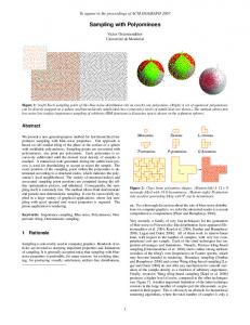
of an addictive Gaussian white noise. We have also compared this with the case where the channel is a noisy LTI channel, and obtained very similar results. We compare all results with what we call the “ideal” receiver, with near-infinite-rate sampling and matched filtering to the pulse shape. In [2] the authors used a first-order method which is very sensitive to noisy conditions. Therefore in our exposition we consider using second-order methods such as ESPRIT [4]. We used a covariance matrix with different oversampling rates, except for the U oversampling where we had to use a smaller covariance matrix. The results are more promising, as shown in Fig. 7. Oversampling improves the estimate of the covariance matrix, and thus leads to better results. Note that in this framework we can use well-studied frequency estimation algorithms to improve performance and/or to reduce complexity.
�����
��
V. C ONCLUSIONS IV. S IMULATIONS We present a series of simulation results of the performance of our algorithm for UWB signals in the presence
Inspired by the recent work on sampling of nonbandlimited signals, we studied communication systems that use bandwidth expansion. In the noiseless case, it is
[4] R. Roy and T. Kailath, “ESPRIT - Estimation of Signal Parameters via Rotational Invariance Techniques,” IEEE Transactions on Acoustics, Speech, and Signal Processing, vol. ASSP-37, pp. 984– 995, July 1989. [5] R. O. Schmidt, A Signal Subspace Approach to Multiple Emitter Location and Spectral Estimation. PhD thesis, Stanford University, Stanford, CA, 1981. [6] E. Sj¨ostr¨om, Singular Value Computations for Toeplitz Matrices. PhD thesis, Link¨oping University, Link¨oping University, Link¨oping, Sweden, 1996.
UWB ESPRIT receiver in AWGN
0
10
−1
10
−2
10
error rate
−3
10
ideal case 2x oversample 4x oversample 8x oversample 16x oversample
−4
10
−5
10
−6
10
−7
10
0
5
10
15
20
25
30
35
SNR (dB)
Fig. 7. Simulation of comparison between matched-filter and ESPRIT for UWB
possible to sample the symbol rate, rather than the much higher chip rate. We investigated the noisy case, where different estimation procedures are necessary. The tradeoff between oversampling above the symbol rate and robustness has been shown. In our example we considered only Pulse-Position Modulation. Note that it is easy to extend this framework to general multilevel/multiphase J modulation (such as QAM) by solving for the values of in Eqn. 2, following the formulation in [2]. L An optimization procedure to obtain the best performance for a given system has been presented, where the frequency estimation component can be replaced by more sophisticated algorithms. Within such a framework, we have shown that it is possible to implement a receiver which operates at near the true rate of innovation, or rate of information, of a communication system. Such a result can be applied to a large class of communication systems, including UWB and CDMA. However, it comes at the cost of SNR. VI. ACKNOWLEDGEMENTS The authors would like to thank Sergio Servetto and Donnacha Daly for careful reviews of the paper and Ian O’Donnell for helpful comments on UWB. R EFERENCES [1] M. Unser, “Sampling-50 years after Shannon,” Proceedings of the IEEE, vol. 88-4, pp. 569–587, April 2000. [2] M. Vetterli, P. Marziliano, and T. Blu, “Sampling signals with finite rate of innovation,” IEEE Transactions on Signal Processing, 2001. Under review. [3] P. Stoica and R. Moses, Introduction to Spectral Analysis. Englewood Cliffs, NJ: Prentice-Hall, 1997.