SISY 2011 • 2011 IEEE 9th International Symposium on Intelligent Systems and Informatics • September 8-10, 2011, Subotica, Serbia
SCADA Element Solutions using Ethernet and Mobile Phone Network Eugen Horatiu Gurban and Gheorghe-Daniel Andreescu “Politehnica” University of Timisoara, Department of Automation and Applied Informatics, Timisoara, Romania e-mails:
[email protected],
[email protected] Abstract—SCADA systems are gaining more popularity, including controlled environment applications. A particularity for these processes is that the distributed controlled environment is scattered in different locations. SCADA human machine interfaces (HMI) are accessed remotely, thus the human observers should not be restrained near the process physical location. One of SCADA application domain is E-Agriculture, where one the field with the main growth is greenhouse automation nowadays. This paper proposes, as initial stage, a viable solution for SCADA telematics system for distributed applications including greenhouse environment control. The key point for this project is to develop a generic telematics system that is integrated in SCADA applications. This system contains the following elements: PIC18F4620 microcontroller, GSM modem, Ethernet controller, RTC board, digital thermometer and a LCD. The main I/O features are: remote command for 5 digital output lines, remote monitoring for 4 input lines and a remote monitoring for a digital thermometer. The remote commands and monitoring are accomplished by using two solutions: 1) GSM/3G Short Message Service (SMS) / phone calling or 2) the web page hosted by the PIC microcontroller. Using this hybrid communication media, GSM and Ethernet, the proposed telematics system gains the flexibility of web access and the high coverage of GSM networks in a fault-tolerance system. The proposed solution was implemented and experimental tested with satisfactory results.
I. INTRODUCTION SCADA systems for automation show a considerable growth over the last years including automotive, home automation and E-Agriculture domains. These application systems require distance controlling and monitoring and thus inherently the rapid development of telematics for SCADA systems. The current trend in SCADA for remote monitoring and command is to use the wireless infrastructure resulting in a decreased interest to the traditional wired systems [1]. Feasibility studies for the GSM infrastructure using SMS where done, showing that this communication type is suitable for implementing distributed control systems data monitoring and acquisition [2]. Modern wireless communication technologies can be applied in distributed control system, e.g., in greenhouse automation or general agriculture automation due to their high flexibility, low cost, and high coverage area. GSM/3G network is a wireless technology for data transmission, being present for a long time on the market, that offers a lot of features and a high percentage of users.
978-1-4577-1974-5/11/$26.00 ©2011 IEEE
GSM/3G networks are offering a very good coverage area worldwide at low costs of ownership, mainly because GSM technology is present on the market for over 20 years, reaching the past decade a high maturity level and gaining a lot of users. Because of the widely coverage, the GSM/3G networks can be used for implementation of telematics applications including automotive, home automation and also E-Agriculture domains. The GSM/3G networks can use the voice capabilities but also the data transfer feature for telematics system usage. Studies regarding the usage of SMS for agriculture specific parameters remote monitoring indicated that the remote system shows good performance and reliability [3]. Telematics systems based on GSM networks can be used in critical safety systems, GPS positioning systems or in traffic reporting or diagnosis. Home automation, building automation, greenhouse automation, E-agriculture have a common background. This includes light and climate control (ventilation, air conditioning, humidity, temperature), control of doors and window shutters, security and surveillance systems. The automated control involved in these types of systems reached a high level of maturity. One problem still remaining is the remote control, distant monitoring and distant diagnosis for those types of systems. Even if there is a lot of distant monitoring and control technologies developed for greenhouse automation the main problem are the reliability and the coverage provided by this system. On one side, the SMS based on GPRS or GSM can meet the communication requirements if we take into account the distance and the coverage, but fail to do so after we consider the costs, possible delays in transmission and small data frames transmitted just 140bytes / SMS. Another possibility is to use GPRS for data transmission [4], but this system requires beside a microcontroller with GPRS module, a remote server that can host a web server. The architecture for creating a remote monitor and command was developed keeping in mind that the SCADA system needs technologies that provide high coverage area, redundancy in case that one communication media fails and also a low cost of ownership. First step was to choose a technology on which will be based the telematics system, thus the Ethernet and GSM/3G network where chosen. Because the telematics is starting to be used more and more in all the automation domains, this paper tries to create a generic SCADA telematics platform that can be successfully used in SCADA systems for distributed control environment. The starting point was the need for a telematics system to be integrated in a SCADA system.
– 303 –
E. H. Gurban et al. • SCADA Element Solutions using Ethernet and Mobile Phone Network
The main problem was that the SCADA system should not restrain its usage due to the close location for all the distributed part of the SCADA system. In conclusion, a generic type of communication with a very good coverage had to be found. Web based distant monitoring and command solution where presented in the last period introducing a different way of handling the monitoring or command part for greenhouse automation [4], [5], [6], that will be the target for our future projects. There are different web based architectures, some web servers are hosted on the microcontroller [5] others on PCs [6]. In this paper, one key concept is the development of an interface with the GSM/3G network that is accomplished by using a cell phone equipped with integrated GSM hardware modem that has AT commands capabilities. This particular approach is taken mainly due to the large number of GSM/3G terminals and modems on the market, the low cost and performance corroborated also with the user high level of acceptance for this common devices. Another key concept is the usage of an Ethernet module that provides the microcontroller the possibility to host a web server, providing the user a web based interface, easy to use with worldwide coverage. In the proposed solution the GSM/3G and Ethernet module where integrated in a single microcontroller based module providing a compact, robust solution for SCADA supervisory and alarm layer. Using a hybrid communication media, GSM and Ethernet, the telematics system gains the flexibility of web access and the high coverage of GSM networks in a fault-tolerance system. II. APPLICATION ARHITECTURE The basic concept was to create a telematics system for SCADA remote monitoring and commands functions. This system implements two ways for SCADA remote monitoring and command, the first is based on SMS/call functionalities provided by GSM/3G network and the second one is accomplished by using a web page interface provided when using a web server. The interface with the GSM network was done using a cell phone equipped with integrated GSM hardware modem that has AT commands capabilities. It was particularly used this approach, because of the large number of GSM terminals on the market at prices very low in comparison with dedicated GSM modules. The web server was implemented on the PIC microcontroller by interfacing to the Ethernet network trough a SPI Ethernet controller: Microchip ENC28J60. The heart of the system is an EasyPIC5 development Board with a PIC18F4620 microcontroller. This is 8bit microcontroller that has enough hardware resources to sustain different system demands. When the microcontroller was chosen, it was taken into consideration the hardware demands for the development of a generic platform, but also the further development needs after the current described phase is accomplished. The proposed system can be remotely accessed, the user has the possibility to command 5 digital outputs, to monitor 4 digital input lines and one digital thermometer. The remote access of the 5 output lines can be done by sending SMS, by making phone calls or by using the web based interface. The status of the input lines / digital thermometer is periodically monitored and their status can
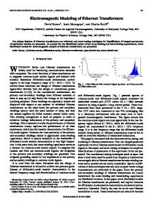
Figure 1. GE-TS schematic
be sent by SMS or seen on the web page hosted by the PIC microcontroller. The GSM-Ethernet based Telematics System project developed a reliable multi-purpose SCADA telematics system that can be personalized to meet different system demands. III.
GE-TS HARDWARE
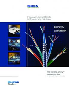
A. Global Schematic The heart of the GSM/Ethernet Telematics System (GE-TS) is a PIC microcontroller (Fig. 1). This is a 8 bit microcontroller from the PIC 18F family controller with 64KBytes of FLASH and 3968 Bytes of RAM, Master Synchronous Serial Port (MSSP) module Supporting 3Wire SPI (all 4 modes) and I2C Master and Slave modes and a Enhanced Addressable USART module. The development board (Fig. 2) presents the EasyPIC5 development board provided by MikroElektronika [7]. The MikroElektronika development system is composed of: development board, programming IDE and additional boards. The development board used is an Easy PIC, this board being compatible with a high range of Microchip PIC microcontrollers. The development board allows PIC microcontrollers to be easily connected to external circuits and a high range of peripheral devices.
– 304 –
Figure 2. MikroElektronika development board
SISY 2011 • 2011 IEEE 9th International Symposium on Intelligent Systems and Informatics • September 8-10, 2011, Subotica, Serbia
Figure 3. Cell phone connection
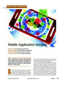
The main features of Easy PIC 5 are: USB 2.0 onboard programmer supports 8 - 40 pin PIC microcontrollers, ICD debugger, supports additional boards provided by MikroElektronika B. Connection with Cellphone The MAX232 is used to convert the TTL voltage levels to the EIA/TIA 574 voltage levels. This solution was preferred as the purpose was to gain interoperability with other communication equipment (Fig. 3). Any cell phone that has a data cable compatibility with EIA/TIA 574 standard can be used, from the hardware point of view. MikroElektronika development board has a MAX232 converter and uses for connection with other equipment a female DB9 connector. The RX and TX connectors are inverted. The compatibility between DLR3P and the development board DB9 connector is assured by using an adaptor. IV.
Ethernet controller the SPI Ethernet Library provided by mikroC [8] was used. Once the first part (initialization and configuration) is run, the software execution is continued with the second part which is processed periodically. The second part consists mainly of routine implementation for monitoring, processing and command. The temperature, four digital inputs, real time clock, occurrence of calls, messages received, occurrence of a scheduled task and the TCP/HTTP requests are monitored. The clients can connect to the web server, hosted by the Pic microcontroller. If the user wants to modify the state of a digital output, a request will be sent to the server which will process the incoming TCP/HTTP request and take appropriate actions. If the users just want to observe the state of the system the web page is refreshed each cycle by the PIC microcontroller. To measure the temperature, DALLAS DS1820 1Wire digital thermometer is interrogated periodically. The temperature is obtained at each running cycle. At each loop, the microcontroller is interrogating the Nokia cell phone for new SMS received. When a new SMS is received, it will be validated by the microcontroller if the sender phone number is one of the 10 valid ones recorded in the cell phone agenda. In the next step, it will start to process the message. If the call number is not valid, an error message will be displayed on the LCD and the SMS will not be processed, so only the valid phone numbers commands are processed by GE-TS.
GE-TS SOFTWARE
A. Software Flowchart The GSM/Ethernet Telematics System, GE-TS, software can be divided in two main parts: the first part consists of initialization and configuration, and the second part is for monitoring, processing and command (Fig. 4). The configuration part runs once, at startup and the monitoring, processing & command runs periodically. The first step is to configure the resources that are needed, here are configured the microcontroller hardware resources, the I/O ports, the timers, the USART module, initialization for the LCD and for the SPI Ethernet controller. To synchronize the data transmission between the GSM and the development board, the USART module is configured for different data transfer speed rates. After each initialization it is verified if the cell phone is sending back an acknowledge. If the acknowledge is indeed sent, the USART initialization state is kept, otherwise another initialization command is run. The next step is to find the phone numbers that are validated for usage by GE-TS. In this first step the ENC28J60 Ethernet controller is also initialized, configuring transmission parameters the MAC, subnet mask, IP for gateway, DNS and the address for the embedded device. For controlling the ENC28J60
– 305 –
Figure 4. SW flowchart
E. H. Gurban et al. • SCADA Element Solutions using Ethernet and Mobile Phone Network
SMS can contain two types of commands, commands that need to be interpreted and processed immediately after reception or commands that will schedule tasks to be executed at a given time – stated in the task request SMS. The microcontroller supports a maximum of 5 tasks that can be recorded and activated at a defined moment of time. Those tasks can be performed daily or just once after the reception. If the task is configured to be run only once it will be deleted from the task queue after the processing. If the SMS consist of an instant activation request, it will be processed immediately. In case the sender command contains a confirmation request, this can be done by calling or sending an SMS depending on type of confirmation requested. The SMS can contain one or more commands. There are 5 types of commands: • digital output lines command, • status request, • call request, • task insertion, • task delete commands. If the task list is full, and the sender is requesting to insert another task in the list, the microcontroller will send a SMS warning message specifying how to delete the current tasks from the queue. Next step is the detection of calls received by the cell phone. The calls are validated if the caller ID is preset in the cell phone agenda. If that happens, it will activate an output of the microcontroller. As a confirmation, the microcontroller will hang up the call. The microcontroller is also processing of the tasks recorded in the task queue. If such tasks exist, the ECU will determine if the current time is the same as the activation request time of the tasks. If they are equal, the task is processed. If the task is not recurrent it will be deleted from the queue, after being processed. B. AT Commands AT commands are a standardized command set used to control a modem. The usage of AT commands offers the possibility to get information regarding the phone, the modem or the subscriber, establish a voice or data connection to the modem, send/receive a fax, send/read/write SMS, read/write/search phone book entries. GSM-TS is based on a GSM terminal provided by the terminal manufacturer NOKIA which can be controlled trough AT commands. A Nokia 6210 cellphone has been used. It belongs to the category of mobile phones with integrated hardware modem and has enough commands provided by the ETS 300 916/ETS 300 585 standard to support GSM-TS full application functionality. From the multitude of standards issued by ETSI [9], [10], allowing flexibility and inter compatibilities in communication networks, eloquent for GSM-TS are the followings: - ETS 300 916 (GSM 07.07 version 5.9.1) – AT commands for voice, conference, access to SIM resources, address book, video memory or keys; - ETS 300 585 (GSM 07.05 version 4.8.1) - AT commands for the SMS (Short Message Service).
V. SCADA TELEMATIC SYSTEM SOLUTION The main functionalities of the GSM/Ethernet Telematics System, GE-TS, are: • interfacing with the GSM/3G, Ethernet network, • monitoring digital inputs, temperature, GSM terminal, Ethernet module TCP/HTTP requests, • command, • user interface on the system LCD and WEB based interface provided by using the Ethernet module A. Interfacing with GSM Network The interface with GSM network is provided by phone’s capability to use AT commands, thus GE-TS is able to perform the following actions: • receiving phone calls • making phone calls • receiving messages • sending messages • GSM additional functions like: hold, reject calls, interrogate the phone agenda, and modifying phone settings. Based on AT commands described in chapter IV - B, this application is capable of making phone calls, receiving messages and of composing and transmitting messages. B. Monitoring The monitoring functions of the system can be categorized into: • function for determining the current status, • function of temperature monitoring, • task queue monitoring based on RTC. The information regarding the inputs/outputs of the system is published on the microcontroller hosted web page. Another way for accessing this data is by using the SMS capabilities of the GE-TS module. The system can send a status SMS that contains the status of the digital I/O lines used by the system, the temperature, the current time and the task queue information. The system status can be requested by a SMS that has in its structure "req.sms" sequence. The status SMS is sent by the system when a SMS request is acknowledged or when a status message is imposed by task activation. Status SMS is composed of: • input lines monitored by the system, • SMS controlled output, • call controlled output, • temperature information, • SMS timestamp, • the number of current tasks and the task list. Status SMS example: “Sat 02.03.11 16:05 #No record#”
– 306 –
SISY 2011 • 2011 IEEE 9th International Symposium on Intelligent Systems and Informatics • September 8-10, 2011, Subotica, Serbia
Figure 6. DCN-TS front/ lateral view
thermometer. The web interface offers the possibility to set desired output for the 5 digital output lines. On the PIC microcontroller hosted page are also enumerate the valid phone numbers that can be used to access the GE-TS features. VI. Figure 5. GE-TS web interface
If there are tasks in the queue, the SMS response will not include the date, time and temperature because the full status cannot fit in a single SMS. This is the format of the SMS: “#Nr req=3” C. Commands The activation command for the 5 digital output lines can be given by: SMS, call, task scheduler and web interface. Besides using the web interface for controlling the output state for the 5 digital lines, the GE-TS offers the possibility to use GSM module for SMS or phone calls based remote command. If the phone number of the caller is considered valid by GE-TS, the system will process the incoming call. After a caller number is validated, the microcontroller will toggle the value of an output line, or set the output for the microcontroller digital output lines. The call is hang up as a result of confirming the received request. Also, the GE-TS can command the output lines when receiving a SMS request. The syntax of a SMS command is: [Identifier]. [Action]. The identifier can take the following values: “LED1”, “LED2”, “LED3”, and “LED4”.The action can be “ON” or “OFF”.
DEVELOPMENT STAGES GE-TS
There had been two development stages for GSM/Ethernet Telematics System, GE-TS. First stage consisted in the implementation of the remote command/monitoring by using the SMS/CALL features on a pic 16F876A. In the second development stage a new, more powerful microcontroller was used, so adding new functionalities was possible. A. Digital Cellular Network Telematics System The first Digital Cellular Network Telematics System, DCN-TS was implemented from ground up, starting with the PCB cabling and ending with the design of the case. DCN-TS was able to monitor the temperature trough a 1wire interface digital thermometer DS1820, monitor the GSM terminal for new SMS /calls, verify the incoming calls/SMS and in case calls where validated, process them. The monitor and the command module are presented in Fig. 6. Interfacing with the user is done through a small LCD, 7 LEDs, and 2 switches. • LED1 - state indicator for direct call, • LED2:LED5 - state indicators for SMS controlled lines,
D. LCD User Interface / Web Based Interface The user is informed about the action that is currently performed or future ones, using a LCD. The LCD is set to display different types of information: receiving an SMS/CALL, sending an SMS, validating procedure status - succeed/failed, error message and task queue information. As seen in Fig. 5, using the web based interface it’s possible to see the current state of the I/O and the temperature provided by the DS1820 digital
– 307 –
Figure 7. DCN-TS components
E. H. Gurban et al. • SCADA Element Solutions using Ethernet and Mobile Phone Network
•
LED6, LED7 - state indicators for switch SW1, SW2. Fig. 7 represents the block diagram of DCN-TS. Due to memory constrains, microcontroller having only 368KB of RAM and the Flash memory 8K, further development for this system couldn’t be done. That’s why GE-TS hardware was chosen to meet the new features that we wanted to implement and also to provide further development possibilities. B. GE-TS GE-TS hardware is based on the same GSM modem, but the microcontroller and development platform has changed. The new microcontroller is a pic 18F4620 providing 64K FLASH and 3968 Bytes of RAM and has the possibility to operate at a 40MHz frequency. The GSM-TS II new features: • RTC module provides the possibility to process pending commands at a specified moment, and to insert the time stamp in the short message service, • a queue of commands to be process at a specific time, once or periodically. The 18F4620 microcontroller has the hardware resources to control an Ethernet board based on Microchip's ENC28J60 stand-alone Ethernet Controller. By using the GSM modem and the Ethernet board the system offers the possibility to remotely command and monitor trough SMS but also trough web access. By using the GSM features and also the Ethernet capabilities, the telematics system had gained the major advantages of these two, the flexibility of web access and the high coverage of GSM networks. C. GE-TS further Development The next step is to test the GE-TS in a greenhouse and to configure/add new functionalities based on the grower requirements. Due to the integration of telematics module in a SCADA system for greenhouses, more functionality could be added. One important feature is to add an alarm handling module to inform the user through SMS, phone call or mail and offers the possibility, for the user, to configure the desired threshold and the expected behavior. Another development direction is to add gateway functionality to the GE-TS module, direction being taken by several authors with very good results [11]. VII. CONCLUSION The main goal pursued when developing the proposed GSM/Ethernet Telematics System (GE-TS) was to create a highly configurable and upgradeable SCADA telematics system based on the GSM and Ethernet network. In the current stage, the project is fully functional, the main objective being to demonstrate the possibilities of monitoring and command through a "low cost" telematics solution based on GSM/Ethernet network. The main I/O features are: remote command for 5 digital output lines, remote monitoring for 4 input lines and a remote monitoring for a digital thermometer. The
remote commands and monitoring are accomplished by using two solutions: 1) GSM/3G Short Message Service (SMS) / phone calling or by 2) using the web page hosted by the PIC microcontroller. By using a hybrid communication media (GSM/3G and Ethernet network) the system provides high coverage, reliability and low cost of ownership in a fault-tolerance system. The current system implementation can easy be updated to monitor and control a wide range of sensors and common devices used in different areas. This project offers a low-cost generic solution for SCADA to be used in various automation domains like home/building automation, E-Agriculture and s.o. This telematics system will be integrated in a SCADA system for greenhouse control. ACKNOWLEDGMENT This work was partially supported by the strategic grant POSDRU 107/1.5/S/77265, within POSDRU Romania 2007-2013 co-financed by the European Social Fund – Investing in People. REFERENCES [1]
G. W. Irwin, J. Colandairaj, and W. G. Scanlon, “An overview of wireless networks in control and monitoring,” Computational Intelligence, Lecture Notes in Computer Science, vol. 4114, pp. 1061–1072, 2006. [2] C-L Tseng, J-A Jiang,R-G Lee, F-M Lu,C-S Ouyang, Y-S Chen, and C-H Chang, “Feasibility study on application of GSM–SMS technology to field data acquisition,” Computers and Electronics in Agriculture, vol. 53, no. 1, pp. 45–59, Aug. 2006. [3] I. A. Aziz, M. H. Hasan, M. J. Ismail, M. Mehat, and N. S. Haron, “Remote monitoring in agricultural greenhouse using wireless sensor and short message service (SMS),” International Journal of Engineering & Technology, vol. 9, no. 9, Oct. 2009. [4] X. Li, Z. Sun, T. Huang, K. Du, Q. Wang, and Y. Wang, “Embedded wireless network control system: an application of remote monitoring system for greenhouse environment,” in Proc. Computational Engineering in Systems Application (CESA 2006), Beijing, China, pp. 1719–1722, Oct. 2006. [5] S. János and G. Martinović, “Web based distant monitoring and control for greenhouse systems using the Sun SPOT modules,” in Proc. 7th International Symposium on Intelligent Systems and Informatics (SISY 2009), Subotica, Serbia, pp. 165–169, Sep. 2009. [6] Yuling Shi, Zhongyi Wang, Xu Liu, Dongjie Zhao, and Lan Huang, “A web-based monitoring system as a measurement tool in greenhouses using wireless sensor networks,” Computer and Computing Technologies in Agriculture, IV IFIP Advances in Information and Communication Technology, vol. 346, pp. 289– 297, 2011. [7] Homepage of MikroElektronika. [Online]. Available http://www.mikroe.com/ [8] MikroC PRO for PIC, User Manual, MikroElektronika, 2009. [9] ETS 300 585, Digital cellular telecommunications system (Phase2); Use of Data Terminal Equipment - Data Circuit terminating Equipment (DTE -DCE) interface for Short Message Service (SMS) and Cell Broadcast Service (CBS)(GSM 07.05), 1997. [10] ETS 300 916, Digital cellular telecommunications system (Phase 2+); AT command set for GSM Mobile Equipment (ME) (GSM 07.07 version 5.9.1.), 1999. [11] O. Mirabella and M. Brischetto, “A hybrid wired/wireless networking infrastructure for greenhouse management,” IEEE Transactions on Instrumentation and Measurement, vol. 60, no. 2, pp. 398–407, Feb. 2011.
– 308 –