Abstract - A decoupling network for two-element closely- spaced arrays is investigated in this paper with rigorous design formulas. The proposed scheme deals ...
FR1E_02
Proceedings of ISAP 2014, Kaohsiung, Taiwan, Dec. 2-5, 2014
A Decoupling Network for Two-Element Array Using Uniform Coupled-Line Sections Cheng-Hsun Wu, Huy Nam Chu*, Chang-An Lin, and Tzyh-Ghuang Ma Department of Electrical Engineering, National Taiwan University of Science and Technology, No. 43, Sec. 4, Keelung Rd., Taipei 10607, Taiwan (R.O.C.) Abstract - A decoupling network for two-element closelyspaced arrays is investigated in this paper with rigorous design formulas. The proposed scheme deals with even-/odd-mode matching and decoupling requirements individually and can achieve overall excellent impedance matching and isolation at the same time. Index Terms — Antenna arrays, coupled lines, decoupling of systems, multiple-input-multiple-output (MIMO) systems, mutual coupling.
I.
INTRODUCTION
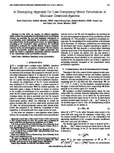
Since the available space in portable devices is relatively limited, the antennas in a MIMO system should be closely deployed and therefore result in significant performance deterioration due to electromagnetic field coupling [1]. To conquer this difficulty, the neutralization line is proposed to eliminate the detrimental mutual coupling between the closely-spaced array elements in a compact platform [2]–[4]. However, the lack of a systematic design procedure makes this technique unfavorable in a variety of circumstances. By utilizing the even-/odd-mode analysis, a new decoupling scheme is proposed and investigated in this paper with design formulas. The proposed network is shown in Fig. 1; it consists of three coupled-line sections with equal even/odd-mode characteristic impedances but different lengths. While the first section serves as delay lines as well as impedance transformers, the other two can independently control the matching and decoupling conditions in the even and odd modes. The design details will be introduced in the following sections. II. DESIGN CONCEPT To simultaneously achieve perfect matching and port isolation in a two-element closely-spaced array, it is known that the S11 = S21 = S22 = 0; in other words, both half circuits in the even and odd modes should be well matched to the system impedance (50 ohms) at the same time, i.e. S11e= S11o= 0 [5]. Referring to Fig. 1, since the input admittance looking into the second section, in either mode, is purely imaginary in the lossless case, the real part of the even-/odd-mode input admittances at the t2 plane should be transformed to Y0 using the first coupled-line section as,
Fig. 1. Proposed decoupling network and its corresponding even- and oddmode half circuits.
(Y11 � Y12 ) � jY0e tan T1 Y0 � jBine , (1) Y0e � j (Y11 � Y12 ) tan T1 (Y � Y ) � jY0o tan T1 Yino Y0o 11 12 Y0 � jBino , (2) Y0o � j (Y11 � Y12 ) tan T1 where Y11 and Y12 are entries of the Y matrix of the closelyspaced array system at the t1 plane. As there are only two equations but three unknowns (Y0o, Y0e, T1), either Y0e or Y0o can be selected first to make the design parameters easily realizable; the remaining two can be solved by the simultaneous equations from the real parts of (1) and (2). With Y0e, Y0o, and T1 specified, the input susceptances looking into the antenna network, Bine and Bino, can be calculated using (1) and (2). For perfect matching in both modes, the susceptances provided by the second and third coupled-line sections should be equal to the negative of the imaginary parts of (1) and (2), which suggests that � jY0o cot T 2 � jBino , (3) jY0e tan(T 2 � T3 ) � jBine . (4) The design parameters (T2 and T3) can be therefore achieved. Yine
Y0e
III. RESULTS AND DISCUSSION For validation, two-element closely-spaced monopole arrays without and with the proposed decoupling network are designed and fabricated on a 60-mil RO4003 substrate (Hr =
457
FR1E_02
Proceedings of ISAP 2014, Kaohsiung, Taiwan, Dec. 2-5, 2014
(a) (b) Fig. 2. Layouts of the closely-spaced monopole array (a) without and (b) with the proposed decoupling network.
Fig. 4. Simulated and measured 2-D radiation patterns of the decoupled monopole array in the xy- and yz-planes.
With the complex electric field data from the HFSS, the ECCs of the closely-spaced monopole array, without and with the proposed decoupling network, are given by 0.183 and 0.001, also indicating a respectable reduction in correlation.
(a) (b) Fig. 3. Simulated and measured S-parameters of the closely-spaced monopole array (a) before and (b) after decoupling.
IV. CONCLUSION
3.38, tanG�= 0.0027); the layouts are shown in Fig. 2. The center frequency is 2.45 GHz, and the element spacing (sa) is 0.07O0. By applying the design concept in Sec. II and converting the parameters into physical footprints, the final dimensions (in mm) are wa= 3.4, wc= 7.6, w1= 0.2, w2= 3.45, la= 21.8, l1 = 24.05, l2 = 4.4, l3 = 35.7, l4 = 24.8, sc= 0.2, sa= 8.4, Lt = 105, Lg= 70, and Wt= 65. The simulated and measured S-parameters of the closelyspaced monopole array, without and with the decoupling network, are shown in Fig. 3(a) and (b), respectively. At the center frequency, the improvement in port isolation is noticeable, while the decoupled array remains in good impedance matching with |Sjj| around -20 dB at the same time. Fig. 4 depicts the simulated and measured two-dimensional radiation patterns of the decoupled array in the principal cuts (xy- and yz-planes). Clearly from the figures, with the decoupling network, the radiation patterns become more directional and uncorrelated. Table I summarizes the simulated and measured peak gains and total efficiencies. A significant improvement is observed. Finally, the envelope correlation coefficient (ECC), a figure of merit to quantify the efficiency of a MIMO array, is G G 2 E1 (T , I ) E*2 (T , I ) d : ³ . (5) Ue G G 2 2 E ( T , I ) d : E ( T , I ) d : ³ 1 ³ 2
A new decoupling network for two-element closely-spaced arrays has been demonstrated in this paper. The proposed scheme, relying on three uniform coupled-line sections in cascade, can deal with the even- and odd-mode matching/decoupling conditions independently. Without a troublesome tuning process, a set of analytical formulas is provided to complete the design. Widening the operational bandwidth would be a good topic worthy of future study. ACKNOWLEDGMENT This work was supported by the National Science Council, Taiwan (R.O.C), under Grants 101-2628-E-011-007-MY3 and 102-2221-E-011-011-MY2. REFERENCES [1] [2]
[3] [4]
[5]
458
M. A. Jensen and J. W. Wallace, “A review of antennas and propagation for MIMO wireless communications,” IEEE Trans. Antennas Propagat., vol. 52, no. 11, pp. 2810–2824, Nov. 2004. A. Chebihi, C. Luxey, A. Diallo, P. Le Thuc, and R. Staraj, “A novel isolation technique for closely spaced PIFAs for UMTS mobile phones,” IEEE Antennas Wireless Propagat. Lett., vol. 7, no. 1, pp. 665–668, 2008. J.-F. Li and Q.-X. Chu, "Proximity-fed MIMO antenna with two printed IFAs and a wideband T-shaped neutralization line," Progress In Electromagnetics Research M, vol. 21, pp. 279–294, 2011. S.-W. Su, C.-T. Lee, and F.-S. Chang, "Printed MIMO-antenna system using neutralization-line technique for wireless USB-dongle applications," IEEE Trans. Antennas Propagat., vol. 60, no. 2, pp. 456–463, Feb. 2012. C.-H. Wu, G.-T. Zhou, Y.-L. Wu, and T.-G. Ma, "Stub-loaded reactive decoupling network for two-element array using even-odd analysis," IEEE Antennas Wireless Propagat. Lett., vol. 12, pp. 452–455, 2013