addition, SCF enables custom communication synthesis, which can provide ... energy advantages, one significant problem that has limited their use is increased ... As opposed to standard software design, specialized devices require designer .... approach where an application is built by connecting constituent tasks.
SCF: A Device- and Language-Independent Task Coordination Framework for Reconfigurable, Heterogeneous Systems V. Aggarwal, R. Garcia, G. Stitt, A. George, H. Lam NSF Center for High-Performance Reconfigurable Computing (CHREC) ECE Department, University of Florida, Gainesville, FL 32611-6200 {aggarwal, garcia, gstitt, george, hlam}@chrec.org
ABSTRACT Heterogeneous computing systems comprised of accelerators such as FPGAs, GPUs, and Cell processors coupled with standard microprocessors are becoming an increasingly popular solution to building future computing systems. Although programming languages and tools have evolved to simplify device-level design, programming such systems is still difficult and time-consuming due to system-level challenges involving synchronization and communication between heterogeneous devices, which currently require ad-hoc solutions. To solve this problem, this paper presents the System-Level Coordination Framework (SCF), which enables transparent communication and synchronization between tasks running on heterogeneous processing devices in the system. By hiding low-level architectural details from the application designer, SCF can improve application development productivity, provide higher levels of application portability, and offer rapid design-space exploration of different task/device mappings. In addition, SCF enables custom communication synthesis, which can provide performance improvements over generic solutions employed previously.
Categories and Subject Descriptors D.2.12 [Software Engineering]: Interoperability – interface definition languages
General Terms Performance, Design, Languages
Keywords Reconfigurable computing, heterogeneous computing, communication, coordination, productivity, portability, accelerators.
1. INTRODUCTION The power bottleneck created by high clock frequencies has forced computer architects to consider alternative methods for increasing system performance, focusing on parallel and often heterogeneous architectures [1]. Systems from domains ranging from embedded systems [2][3] to high-performance computing [4][6] now increasingly combine microprocessors (which may contain heterogeneous cores [7]) with devices such as field-
Permission to make digital or hard copies of all or part of this work for personal or classroom use is granted without fee provided that copies are not made or distributed for profit or commercial advantage and that copies bear this notice and the full citation on the first page. To copy otherwise, or republish, to post on servers or to redistribute to lists, requires prior specific permission and/or a fee. HPRCTA'09, November 15, 2009, Portland, Oregon Copyright © 2009 ACM 978-1-60558-721-9/09/11... $10.00
programmable gate arrays (FPGAs), graphics processing units (GPUs), and other devices [7-13]. Numerous studies have shown that accelerator-based heterogeneous systems can obtain performance improvements ranging from 10× [14] to more than 1000× [15] compared to microprocessors, while also improving energy efficiency [16]. Although heterogeneous systems have numerous performance and energy advantages, one significant problem that has limited their use is increased application design complexity. As opposed to standard software design, specialized devices require designer expertise to specify a custom design, often using multiple languages and tools. As an example, a designer for a system with an FPGA accelerator will likely have to: (a) perform HW/SW partitioning to map program regions to the microprocessor or FPGA; (b) create a custom circuit; (c) describe the circuit in a hardware description language; (d) describe the software in a high-level programming language; (e) establish communication between the microprocessor and FPGA using vendor-specific methods; (f) write code to convert between data formats on each source and destination device; (g) synthesize, place and route the circuit using CAD tools; and (h) compile the software into a binary executable. Simplifying this complicated process has been the focus of a tremendous amount of recent design automation and CAD research involving languages, high-level synthesis tools, and hardware/software partitioning tools. Although language and tool research continues to simplify devicelevel design for specialized devices, heterogeneous systems have system-level design issues that have received limited attention. Such is the case with communication and synchronization (herein collectively referred to as coordination) between heterogeneous processing devices, which is often performed in an ad-hoc manner, requiring significant coding modifications for porting an application to a different system, or even migrating parts of the application onto different devices of the same system. Ideally, code for a task running on a specialized device in a heterogeneous system could be written independently of the other devices, tasks, and of the communication architecture used by the system. To achieve such functionality, we introduce the SystemLevel Coordination Framework (SCF), which simplifies application design for heterogeneous systems by enabling transparent communication and synchronization between tasks running on different devices. SCF consists of a library of message-passing coordination primitives suitable for potentially any language or device, a framework that allows an application to be expressed as a static task-graph and each task of an application to be defined in potentially any language, and a set of tools that can create customized communication methods for a given system architecture based on the mapping of tasks to devices. With SCF, many low-level architectural details are hidden from the application designer, allowing them to simply define each task in
a language of their choice, while specifying coordination between tasks using message-passing primitives. Furthermore, SCF enables rapid exploration of different task-to-device mappings without modifications to task definition code, often resulting in both improved designer productivity and system performance. Our results demonstrate that approximately 5× productivity improvement is achievable for the case study featured in this work with minimal performance overheads. The remainder of the paper is formatted as follows. Section 2 discusses previous work. Section 3 provides an overview of SCF. In Section 4, we discuss research challenges involved in enabling SCF and the set of tools associated with SCF. Section 5 evaluates the framework through a prototype of SCF for our experimental system and presents results. Finally, Section 6 provides a summary of conclusions and directions for future work.
2. PREVIOUS WORK Conventionally, developers of parallel programs have performed coordination using message-passing libraries such as PVM [17], MPI [18], etc. However, these techniques are typically limited to homogeneous systems of microprocessors connected via commodity interconnect technology (e.g., Ethernet, InfiniBand). In recent years, researchers have extended message passing to a heterogeneous mix of microprocessors connected via different network technologies [19-21]. Although heterogeneity is supported by these libraries, it has been limited to only a variety of microprocessors. SCF extends this concept by supporting heterogeneity between microprocessors and potentially any type of specialized accelerator devices. SCF shares similar concepts with other academic projects that aim to improve designer productivity for heterogeneous systems. Ptolemy [22] studies modeling, simulation, and design of concurrent real-time embedded systems based on different models of computation. SCF also assists with the design of applications using different models of computation by enabling designers to
define tasks in any language, and then using message passing to communicate between tasks. Auto-Pipe and the X language presented in [23] provide a framework for designing pipelined applications distributed across resources of a heterogeneous system. Although SCF adopts a similar approach, it extends this concept to allow a designer to specify applications with arbitrary task-graphs. In addition, SCF enables custom communication synthesis to specialize the communication infrastructure to the capabilities of each device and platform in a system. TMD-MPI [24] extends the MPI library to support message passing between heterogeneous devices, such as a mix of FPGAs and microprocessors. Although conceptually similar, SCF has several novel aspects. For instance, TMD-MPI uses a dynamic, task-graph representation of an application and a communicationarchitecture based on packet-switched, Network-On-Chip (NoC) design. In contrast, applications are defined as static task graphs in SCF, which because of a known mapping can yield designs which provide improved performance. Numerous high-level synthesis and hardware/software partitioning approaches automatically generate FPGA circuits from high-level code [25][29]. By contrast, SCF allows tasks to be defined using multiple languages and tools which aids in efficient use of the unique resources of each device in a heterogeneous system. Recently, much effort has been channeled towards standardizing the interface between microprocessors and enhanced devices such as FPGAs [26] and GPUs [27]. Focus of these efforts has been on low-level interaction between accelerator devices and microprocessors, not making any assumptions on higher-level forms of communication and synchronization. The scope of SCF is much larger and complements such efforts, as it can overlay a coordination framework on top of such existing APIs/languages.
3. SCF OVERVIEW
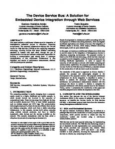
Figure 1: Application design philosophy using SCF. (a) Designer defines tasks independently from task graph and device mapping, (b) creates a task graph by simply interconnecting tasks without changing individual task definitions, and then (c) maps tasks onto devices, while using (d) automated communication synthesis to create efficient coordination mechanisms based on the mapping.
Figure 1 presents an overview of the application design methodology with SCF. This description illustrates a bottom-up approach where an application is built by connecting constituent tasks. However, it can easily be adapted to a top-down design flow by switching the order of the first two stages involved in the process. The designer begins by defining individual tasks as shown in Figure 1(a), using potentially any language, compiler, or synthesis tool per task, thus enabling tool-chain interoperability by allowing different tasks to be written in different languages. Such behavior is critical for heterogeneous systems, where each device may require a different, specialized language [[28]-[30]]. Existing IP cores could also be easily used as task definitions. An important part of each task definition is defining the input and output to other tasks, which can have a large effect on designer productivity. Without SCF, defining task interactions is dependent on the source device and the receiver device, often requiring different device/platform-specific APIs for different mappings. In many cases, changing a mapping requires time-consuming modifications to task definition code. With SCF, a designer specifies all task interactions using a message-passing library called the System Coordination Library (SCL). When defining task interactions with SCL, a designer can be completely unaware of the source or destination device, a key advantage that enables task portability across multiple devices, task reuse in different applications, and transparency of low-level, device-specific communication details. Furthermore, because SCF is aware of the source and destination device for all inter-task data transfers, SCF can allow for automatic conversion between data formats, which further improves designer productivity. After defining individual tasks, the designer then builds the complete application by simply connecting inputs and outputs of the various tasks to form a task graph, as shown in Figure 1(b). Note that this process does not require any changes to the definition of the individual tasks. Currently, SCF can map a task to any device, provided that the code for the task can be implemented on that device. In the worst case, a designer would have to provide task code for each device under consideration. However, improvements in high-level synthesis tools (e.g. C to VHDL) can provide the capability of converting task-definition code of one device to another. SCF does not attempt to automate this conversion of code specified using a particular language or vendor tools to another. Once the task graph is defined, the designer maps individual tasks to specific devices in the system architecture (as shown in Figure 1(c)), again without making any modifications to the task definition code or the task graph of the application. SCF can be used with systems from domains ranging from high-performance computing (HPC) to embedded computing. Figure 1(c) shows several examples of system architectures where SCF can be employed such as, a cluster of CPU nodes (HPC system) optionally equipped with accelerators, a combination of FPGAs and embedded processor (HPEC system), or a system based on a stand-alone FPGA (embedded system). As shown in Figure 1(d), SCF uses the specified mapping to automatically implement all data transfers in the task graph using the specific communication capabilities of the system. For example, in a platform comprised of a host microprocessor and an accelerator board with multiple FPGAs (such as our experimental
system in Section 5), SCF could implement communication between any FPGA and the host CPU using on-board memory, whereas communication between different FPGAs could be implemented using physical wires on the board, while hiding all implementation details from the designer. Furthermore, knowledge of task interaction and their specific mapping onto system resources prior to compilation allows SCF to perform optimizations for reconfigurable devices such as FPGAs, that are not possible in approaches that use dynamic routing to enable arbitrary communication between tasks, such as packet-switched, NoC design employed by [24]. Such optimizations can improve application performance and reduce area requirements. The transparency provided by SCF enables a designer to rapidly explore mappings of tasks to different devices, which is often critical for meeting design constraints. Although much previous work has focused on automatic design-space exploration [31][32], such exploration is still largely a manual process for heterogeneous systems. It should be noted that SCF itself does not provide any automated design-space exploration. Rather, this work abstracts away from the designer the details of coordination between various tasks mapped over heterogeneous resources. Designers may still perform optimization and design-space exploration by means of external tools, and SCF provides an easyto-use entry point for implementing those designs. The following subsections explain SCF in more detail and discuss the programming and communication model adopted by this framework.
3.1 Programming Model There are four terms that define the SCF programming model. A task in SCF is the finest, indivisible unit of computation that can be mapped onto a device. Each SCF task has inputs and outputs represented using the SCL message-passing library. Taskdefinition code implements the computational portion of a task using code in potentially any language such as C++, VHDL, Impulse-C, CUDA, OpenCL, etc. As long as SCL messagepassing constructs can somehow be specified in a language, SCF can support task definitions using that language. Whereas the task definition code defines behavior and interactions of individual tasks, a task graph in SCF defines communication between the tasks by connecting the inputs and outputs of various tasks together, where each edge represents a communication stream. Finally, a mapping in SCF defines how tasks are mapped onto specific devices and system resources.
3.2 Architectural Model To enable coordination between heterogeneous devices on as many systems as possible, SCF uses a hierarchical architecture model that captures structures common to heterogeneous systems, while abstracting away details that designers may not require. The
Figure 2: Architectural model of an example system.
Table 1: System Coordination Library (SCL) primitives. Function
API
Type
Initialization
SCL_Init
Setup
Termination
SCL_Finalize
Setup
Send
SCL_Send
Point-to-Point
Receive
SCL_Recv
Point-to-Point
SCF architecture model consists of three levels of abstraction: devices, platforms, and systems. All SCF tasks execute on SCF devices, which are the finest-grained computational resources of a given system. Every SCF device is part of an SCF platform, which is a subsystem containing a set of SCF devices interconnected by a specific communication topology. Each SCF platform is part of an SCF system, at the top of the hierarchy, which connects a set of platforms using a specific communication topology. Figure 2 illustrates how SCF architecture models can be used to represent common systems. The figure shows a representation of a cluster of nodes connected over Ethernet (or any other network technology), where some nodes consist of a CPU (D1 devices in Figure 2), or a CPU and an accelerator board, each having multiple FPGAs (D2 and D3 devices). This architecture is represented as an SCF model in the following way. The FPGAs and CPUs are SCF devices, each node collectively acts as an SCF platform, and the cluster of all nodes forms an SCF system. The different levels of abstraction are not necessarily mutually exclusive; a single physical device could be a SCF device, platform, and system. For example, platform P1, which is comprised of a single device, is both an SCF device and platform.
3.3 Communication Model One key advantage to the multiple levels of abstraction in the architecture model is that communication can be made transparent to the designer by distributing communication responsibilities throughout the system. Furthermore, such transparency eases conversion of existing devices and platforms into SCF systems. SCF-compliant devices are capable of handling all device-level communication, which we define to be communication between tasks mapped onto the same SCF device. For example, a microprocessor is SCF-compliant if it is capable of supporting communication between multiple tasks mapped onto it. The physical implementation does not affect SCF compliance and could vary for different devices; it could be achieved via a message-passing library or message queues supported by operating systems. Similarly, SCF-compliant platforms provide communication routines that are responsible for all data transfers when the receiver is not implemented on the same device, however on another device of the same platform. SCF platforms are capable of transferring messages to the appropriate SCF device in target platform. Again, the physical implementation of such communication could vary for different platforms. For example, in an SCF platform containing multiple processor cores, messages could be passed through FIFOs in shared memory whereas, for an SCF platform comprised of multiple FPGAs, streaming data transfer could be achieved through physical wires. Alternatively, SCF resorts to the system-level communication routines if the receiver task is mapped on a different platform.
Despite the existence of distinct communication levels, SCF hides these levels from designers, who are instead exposed to a single communication API. Without SCF, a designer would have to go through an extensive process of using ad-hoc methods of establishing communication between any two devices on which the communicating tasks are mapped. Furthermore, the designer would have to re-establish the communication mechanism following any changes in the resource mapping. With SCF, a designer simply specifies the input and output of each task while relying on CAD tools (discussed in Section 4) to implement the communication. Communication between SCF tasks uses a synchronous messagepassing model, which is widely used in the parallel computing community [33]) in which all communication in a task-definition code is specified explicitly, as function calls that send or receive data and require participating tasks to synchronize before performing the data transfer. Such a model is generic enough to be adapted to potentially any programming model associated with any device. Table 1 presents the coordination primitives currently supported by SCL. The setup routine, SCL_Init, performs initialization operations and allocation of resources for all levels of communication and underlying libraries. SCL_Finalize performs complementary termination functions such as deallocation of the resources which were setup during initialization. SCL_Send and SCL_Recv are synchronous blocking communication calls that provide data transfer between tasks. In Sections 4 and 5 we further describe how this simple set of communication routines can be adapted to various programming models associated with different devices. Note that this API is intentionally much simpler than other message-passing libraries (e.g., MPI), which typically contain constructs for scatter, gather, broadcast, etc. With SCF, a designer defining a task does not need to know if the inputs and outputs of the task are used for point-to-point communication or collective communication. The designer simply defines the inputs and outputs of the task. Then, at the task-graph level, collective communication operations can be specified via specialized edges between tasks. By separating specialized communication from task definitions, SCF increases portability of task-definition codes to different applications. The SCF tool being developed for describing task graphs currently supports unicast edges (single source, single receiver) and multicast edges (single source, multiple receivers). A broadcast can be considered as a special case of multicast edges, where all the tasks in the application
Figure 3: SCF tool flow.
which uniquely identifies an SCF device in the system). Although this mapping process is currently performed manually, existing design-space exploration techniques could be integrated into the SCF tool flow to provide optimal mapping suggestions to designers.
Figure 4: Example application in SCF environment. receive from the multicast edge.
4. TOOL FLOW The SCF tool flow shown in Figure 3 begins with a task definition step. Designers define the computations of tasks, or use appropriate cores, using any language, compiler, or synthesis tool, while defining all task interactions using API functions of SCL. Figure 4(a) shows the task graph of an example application consisting of two tasks, which will be mapped to a CPU and FPGA, respectively. As shown in Figure 4(b), one task, written in C++, generates random numbers and outputs the random numbers to an output called “out1” while the other task, described using Handel-C, receives these numbers through input called “in1” and accumulates them. Note that these two tasks are defined independently of each other, using conventional programming languages. The communication is specified using SCL, which is adapted to meet the requirements of the programming environment associated with the target device. After defining tasks, the designer performs task graph definition, which consists of instantiating tasks and connecting inputs and outputs of the tasks using different types of edges. Figure 4(c) shows an example task graph definition (“.scl” file) specified using the SCF tools. This file supports two major components, namely tasks and edges. Each individual task of the application is instantiated independently in this file, along with a list of its inputs and outputs. The edges are used to specify the interconnections between various tasks. Loop constructs are provided for effortless scaling of parts of a task graph. As shown in Figure 4(c), the output of task “random” is connected to the input of task “accumu” through the “edge1” edge. Mapping is responsible for determining which SCF resource in the system will execute each task. An example mapping (“.map” file) is shown in Figure 4(d). It includes various attributes for each task that collectively indicate the resource mapping, such as target IDE, communication libraries available at different levels of hierarchy (device, platform, and system), and most importantly, the target resource (specified by means of an SCF device address,
Communication synthesis analyzes the mapping and the architectural model to automatically create efficient implementations for all edges of the task graph. At each level of hierarchy in the SCF architecture model, communication synthesis determines what mechanisms to use, and based on this information it generates definitions of the required SCL functions for different devices and platforms. In the simplest case, communication synthesis determines if an edge of the task graph corresponds to device-level, platform-level, or system-level communication and translates SCL functions to the underlying library specified in the mapping file. For example, on a platform consisting of a CPU and PCI-X FPGA board, communication synthesis would define an SCL send from the FPGA to another device using the vendor API to transfer data over PCI-X. Although communication synthesis currently implements all communication as a mapping onto underlying vendor API calls, there are numerous possibilities for future work. For example, communication synthesis could potentially implement a broadcast between tasks on a single FPGA with just wires and a small amount of control logic. The SCF tools extract information from the “.scl” and “.map” files, and further invoke separate plug-ins (one for each IDE) to auto-generate the SCL communication routines for different programming languages. For the example showed in Figure 4, there will be a separate plug-in for C++ and Handel-C, each of which will generate the behavior of the SCL_send and SCL_receive routines for their respective tasks. Such a structure allows for new computational devices along with their programming languages and tools to be easily integrated into SCF, by simply creating a plug-in for the new tool (or programming language). We hope such a framework will be amenable to vendors of future technology, and provide an easy mechanism for using their technology with other devices in the system. After communication synthesis, the user combines the definitions for SCL functions with their corresponding taskdefinition code and compiles them collectively using the native compiler of the associated programming language to form an SCF executable that can run on the corresponding system.
4.1 Execution Model Interfacing One obvious challenge of SCF is enabling transparent coordination between different execution models (e.g., C and VHDL). In Section 3.3, we described the semantics of the message-passing model, which are simple yet sufficient to meet requirements of communication with most device architectures. To allow tasks from different execution models to co-exist, SCF requires communication between any two tasks to be preceded by a mutually agreed handshaking protocol. In addition to the synchronization, the implementation of communication functions in SCL is also responsible for ensuring the consistency of data as it moves from the context of one execution model to another. Consider an example of a data transfer from a task written in C for a CPU to a task written in VHDL for an FPGA. The semantics of message transfer are different for both the devices, and hence communication is established by transferring the data into an
intermediate memory location from the source, which is then read by the destination task. In this paper, we illustrate an example of adapting such semantics to the execution model of an FPGA. The send and recv methods, commonly implemented as function calls for processors, were emulated as entities described using any HDL for an FPGA. These entities implement a simple communication protocol that enables FPGA tasks to communicate with other SCF devices in the system. The user application connects to these entities through data and control ports and performs data transfers by simply supplying the required control and data values.
4.2 Automatic Data Conversion Passing data and control messages across varied platforms requires some mechanism of translation of data to a form understood by the local resources. The need for representing data in standardized format across a system of diverse resources has resulted in several standards, such as eXternal Data Representation (XDR) [34], Structured Data eXchange Format (SDXF) [35], and many more. However, the target systems for these standards have been loosely-coupled systems distributed over a wide-area network. The overhead generally associated with these schemes renders them less effective for systems of closely coupled resources and HPC applications. In our work, we use a modification of an approach employed by OpenMPI [20], which provides transparent translation of data between source and destination entities. Since only send and receive semantics are required in SCF for any exchange, it is sufficient to employ a data representation which is compatible with both the sender and receiver of data, instead of a data format that is compatible with all the devices in the system. Data conversion operations are performed by the sender into a representation compatible with the receiver. The SCF tools are informed about the appropriate conversion routines that need to be employed, through the information specified in the mapping file. These operations are automatically inserted during the process of custom communication synthesis on a per-need basis. If both communicating entities use the same data representation, these operations are omitted to avoid the overhead of conversion. A notable feature of SCF data conversion is the provision for user-defined bit-width. This feature allows for special devices which are capable of manipulating the data at the granularity of bits with the flexibility of passing data of arbitrary bit-widths. As an example, for two communicating tasks mapped onto the same FPGA, it may be most meaningful to synthesize connecting wires of the required bit-width (to conserve resources), as opposed to restricting to the size of one of the data types defined by any standard. The current prototype of the tool does not include this feature to support automatic data conversion, but it will be the focus of future work.
5. RESULTS AND ANALYSIS In this section, we present experiments illustrating the productivity and performance advantages of SCF. First, we describe our experimental system and the prototype of SCL which we developed to support this system in SCF. We then demonstrate the advantages of custom communication in SCF, by comparing it with previous work based on a packet-switched, NoC communication architecture. Finally, we demonstrate the benefits
Figure 5: SCF architectural model for experimental system. of rapid-design space exploration using SCF through a case study featuring a target-tracking application.
5.1 Experimental Setup The system used in our experiments consists of two Windows server nodes connected via Gigabit Ethernet. The first node is comprised of a 2GHz Athlon 3200+ processor and equipped with a PROCStar-II FPGA board from GiDEL. This FPGA board features four Altera Stratix-II EP2S180 FPGA accelerators, each with an external DDR memory of 128MB. The board sits in a 64bit PCI-X slot. The second node is comprised of a 3 GHz Xeon processor. To evaluate SCF, a set of prototype tools were created using the Eclipse environment [36][37], which allow designers to specify the task graph definition (“.scl” file) and the mapping information (“.map” file) for the application. The target system is represented in the SCF architecture as follows (shown in Figure 5). The combination of the four FPGAs and the host CPU form an SCF platform (P1 in the figure) and the second CPU forms another SCF platform (P2 in the figure). These two platforms collectively form our experimental SCF system. Each FPGA and CPU is an SCF device. We developed our coordination library (SCL) for our target system to support various levels of communication in the system. System-level communication between CPUs is established using MPI as the underlying communication mechanism. Platform-level communication on the CPU (P1 in Figure 5), which allows it to interact with the FPGAs, employs API calls provided by GiDEL. Device-level and platform-level communication on the FPGAs is supported by send and recv entities which were developed in VHDL and are analogous to send/recv function calls on a CPU. The entities connect to the user’s VHDL applications through data and control ports, and execute a simple communication protocol to communicate with the host CPU and other FPGAs when signaled by the user application. Note that a designer is not exposed to MPI or GiDEL APIs. Instead, a designer simply specifies all task communication using the SCL calls, which SCF tools automatically map onto underlying APIs (e.g., MPI and the GiDEL API in our case).
5.2 Custom Communication Synthesis One of the advantages of SCF is its ability to synthesize custom communication well suited to the requirements of the application and the capabilities of the system. We demonstrate the advantages of such a scheme versus a generic, packet-switched solution using a simplified application, which involves sending data from two tasks to a third task. The task graph of the application is shown in Figure 6 (a), in which tasks T2 and T3 send data to T1. The figure
Figure 7: Task graph for target-tracking application. characteristics required for a particular target-object. Different targets have varying requirements which mandate an appropriate computational platform such as an FPGA, an embedded processor or a desktop processor (CPU).
Data Transferred
Execution Time (ms) NoC-based Design (a)
Speedup SCF Custom Communication (b)
4MB
16.8
8.4
2
8MB
33.6
16.8
2
(d) Figure 6: (a) Task graph of an application implemented using (b) a NoC-based design and (c) SCF custom communication, which (d) results in a speedup of 2×. also shows two possible designs for the example application, both of which were implemented on a single FPGA. The first design (Figure 6(b)) employs a simple router that has a connection to each task with a FIFO to buffer outgoing data on its output ports. While this design is generic and can support a variety of permutations for data communication between connected tasks, it fails to capture information specified by data dependencies in the task graph. The second design (Figure 6(c)), alternatively, adopts a customized design based on details of data communication extracted from the task graph. It instantiates T1 with two ports and connects them to T2 and T3 directly. As a result of this optimization, the latter design offers superior performance over the generic solution, as indicated by application execution times for two different data sizes in Figure 6(d). In a similar manner, custom communication, one of the important components of SCF, can lead to better application designs in other situations. Although communication synthesis is currently defined by implementing all communication as a mapping onto underlying vendor-API calls, there are numerous automatic synthesis possibilities for future work.
5.3 Case Study: Target Tracking Target tracking using Kalman filtering [38] is a method for predicting the trajectory of environmental targets such as vehicles, missiles, animals, hostiles, or even unidentified objects. We selected this algorithm due to its numerous constraints that are often met using heterogeneous devices. There are a variety of factors such as error tolerance, sampling rate of input, target proximity to sensors, etc. that determine the exact operational
In this study, we analyze the overall performance of the system by using SCF to rapidly evaluate different resource mappings of our target-tracking application which tracks three objects using three Kalman filters (one each). Figure 7 shows the task graph of the application. Task T1, the sensor process, creates the inputs for all three filters and is implemented in C++. The three Kalman filters (tasks T2, T3, T4) can be mapped on a CPU (with its design implemented in C++) or on an FPGA (as a VHDL design). Table 2 presents execution times of the application under various mapping scenarios for three different systems. System I is our experimental system (described in Section 5.1). Systems II and III represent notional systems, emulating the characteristics of a system that has lower bandwidth and higher latency of communication between the CPU and FPGAs. When power consumption is a major consideration, systems often employ FPGAs running at a lower frequency, perhaps attached to the system over a lower-speed bus. We implemented these emulations by adding extra delays on the FPGA in our experimental system to reduce bandwidth. The rows of the table represent the number of tasks (amongst T2 to T4) mapped to CPUs and FPGAs. T1 is always mapped on the CPU device of platform P1 (in Figure 5). Each of the other three tasks either time-shares the CPU device on platform P2 with other tasks mapped onto it or executes on an FPGA on platform P1. Table 2 shows that the three systems, although similar, yield different optimal mappings (where optimal mapping is defined as the mapping which achieves best performance and, in case of tie, with least number of FPGAs). With SCF, exploring these different Table 2: Execution time of target-tracking application under different mapping scenarios for three systems. Speedup shows performance gain of optimal mapping (highlighted in bold) compared to all-CPU baseline (i.e. 3-CPU, 0-FPGA mapping). Mappings
Execution Time (ms) System I
System II
System III
3-CPU, 0-FPGA
243
243
243
2-CPU, 1-FPGA
152
152
167
1-CPU, 2-FPGA
67
86
167
0-CPU, 3-FPGA
8
86
167
28.3
2.8
1.4
Speedup
Table 3: (a) Productivity and (b) Overhead measurements. (a) Productivity improvement (for FPGA comm.) Baseline With SCF SLOC 357 112 Development hours
Improvement 3.18×
Conservative
40 hrs (1 week)
16 hrs (2 days)
2.5×
Optimistic
80 hrs (2 weeks)
16 hrs (2 days)
5×
(b) Overheads (on FPGA) Performance
Baseline 76MHz
With SCF 75MHz
ALUTs used
2095/143520
2152/143520
11%
12%
Interconnect resources used
mappings only required simple modifications to the resource mapping file, and none to source code. The SCF communication synthesis tool adapted the communication infrastructure based on information in the mapping file. In contrast, any such changes traditionally would require modifications to the application source code and designer intervention to create communication infrastructure to match the new resource mapping. Moreover, that process would have to be repeated multiple times until a suitable level of performance is obtained. With SCF, we were able to perform design-space exploration rapidly, which led to speedups ranging from 1.4 times faster to more than 28. In order to understand productivity gains obtained by employing SCF, we recorded development hours that we spent during our experiments, in addition to source lines of code (SLOC) involved in certain parts of the application code. Table 3(a) shows the increase in source lines of code involved for establishing communication from the CPU to each FPGA without SCF. A large part of this improvement comes from hiding details of communication from the designer while presenting an easily used interface through SCL. Although these numbers are specific to our experimental system and team personnel, we believe them to be a fair estimate of improvements we expect to obtain with SCF. The development hours reported in the table include time spent in modifying the application design to match the resource mapping, in addition to time required for learning the vendor-specific APIs, both of which can be reduced significantly when using SCF. Based on these results, we estimate SCF framework can reduce development time and improve productivity by a factor of approximately five. The optimistic case in Table 3(a) represents a case where designer is unfamiliar with the system, and thus has to undergo a steep learning process for the APIs for each device. The conservative case represents an experienced designer who is familiar with the tools and vendor-APIs for that particular system. Table 3(b) lists the overhead incurred by our VHDL design where the communication infrastructure was created using the SCF, in comparison to optimized, hand-written design developed for the same application. It is clear from these results that the communication routines employed by the tools result in modest overheads in terms of both resources and performance.
6. CONCLUSIONS To address challenges involving task coordination in future reconfigurable, heterogeneous systems, we have introduced a system-level coordination framework that enables communication and synchronization between tasks running on heterogeneous processing devices in a system. SCF hides the low-level architectural details from the application designer, resulting in improved productivity. By allowing designers to define communication independently of the devices in a system, SCF improves application portability. In addition, SCF allows designers to define tasks using potentially any language, which enhances the inter-operability between different vendor tools. We analyzed a prototype of the framework and its associated tools and libraries through various experiments. Our experiments indicate that custom communication, one of the important components of SCF, creates designs that offer superior performance over a generic solution. The performance advantages of SCF were illustrated with a target-tracking application study that achieved a speedup of 28× by using the rapid design-space exploration enabled by SCF. Higher level of abstraction offered by this framework leads to substantially improved designer productivity, with current estimates ranging up to 5×. In future, we intend to add support for automatic data-conversion mechanisms as outlined in this paper. We also plan to extend the communication infrastructure to incorporate non-blocking communication and thus allow applications to exploit more concurrency. In addition, we would like to standardize the mechanism of supporting new platforms in this framework to allow vendors to comply with requirements in an easy manner.
7. ACKNOWLEDGMENTS This work was supported in part by the I/UCRC Program of the National Science Foundation under Grant No. EEC-0642422. The authors gratefully acknowledge vendor equipment and/or tools provided by GiDEL that helped make this work possible. We also thank Abraham Sanchez, M.S. student, in our lab for his contributions to this work.
8. REFERENCES [1] Olukotun, K. and Hammond, L. 2005. The Future of Microprocessors. Queue. Vol. 3, Issue 7 (Sep 2005), pp. 2629. [2] Bhat, P.B., Lim, Y.W., and Prasanna, V.K. 1995. Issues in using heterogeneous HPC systems for embedded real time signal processing applications. Proc. of Second International Workshop on Real-Time Computing Systems and Applications (25-27 Oct 1995), pp. 134-141. [3] Erbas, C. and Pimentel, A.D. 2003. Utilizing synthesis methods in accurate system-level exploration of heterogeneous embedded systems. IEEE Workshop on Signal Processing Systems (27-29 Aug 2003), SIPS 2003. pp. 310-315. [4] SRC Computers, Inc. 2009. MAPstation workstations. www.srccomp.com/products/mapstation.asp, (website accessed on July 12, 2009). [5] XtremeData, Inc. 2009. In-Socket Accelerators. http://www.xtremedatainc.com/index.php?option=com_conte
nt&view=article&id=109&Itemid=170, (website accessed on July 12, 2009). [6] El-Ghazawi, T., El-Araby, E., Huang, M., Gaj, K., Kindratenko, V., and Buell, D. 2008. The Promise of HighPerformance Reconfigurable Computing. IEEE Computer, vol.41, no.2 (Feb 2008), pp.69-76. [7] F- Chen, T., Raghavan, R., Dale, J. N., and Iwata, E. 2007. Cell broadband engine architecture and its first implementation: a performance view. IBM Journal of Research and Development 51, 5, 559-572. [8] Altera Corp. 2008. Stratix IV Device Handbook. Altera Corp. [9] Xilinx, Inc. 2008. Virtex-5 Family Overview. Xilinx, Inc. [10] Nvidia Corp. 2006. Nvidia GeForce 8800 GPU Architecture Overview. Nvidia Corp [11] Nvidia Corp. 2009. Nvidia tesla Tesla S1070 specifications. Nvidia Corp. [12] Ambric, Inc. 2008. Ambric technology backgrounder. http://www.ambric.com/technology/technologyoverview.php [13] ClearSpeed Technology PLC. 2007. CSX600 Architecture. Whitepaper. ClearSpeed Technology PLC. [14] Shih, K., Balachandran, A., Nagarajan, K., Holland, B., Slatton, C., and George, A. 2008. Fast Real-time LIDAR Processing on FPGAs. Proc. of International Conference on Engineering of Reconfigurable Systems and Algorithms (July 14-17 2008), ERSA 2008. Las Vegas, NV. [15] Storaasli, O. 2008. Accelerating Genome Sequencing 1001000X with FPGAs. Many-core and Reconfigurable Supercomputing Conference (April 2008), MRSC 2008. [16] Williams, J., George, A., Richardson, J., Gosrani, K., Massie, C., and Lam, H. 2009. Characterization of Fixed and Reconfigurable Multi-Core Devices for Application Acceleration. ACM Transactions on Reconfigurable Technology and Systems. Accepted to appear. [17] Sunderam, V. S. 1990. PVM: A Framework for Parallel Distributed Computing. Concurrency: Practice and Experience 2, 4, (Dec 1990), pp 315—339. [18] MPI website. http://www.mcs.anl.gov/research/projects/mpi/, (website accessed on July 12, 2009). [19] Lastovetsky, A. and Reddy, R. 2006. HeteroMPI: towards a message-passing library for heterogeneous networks of computers. J. Parallel Distrib. Comput. 66, 2 (Feb. 2006), 197-220. [20] Graham, R.L., Shipman, G.M., Barrett, B.W., Castain, R.H., Bosilca, G., and Lumsdaine, A. 2006. Open MPI: A HighPerformance, Heterogeneous MPI. Proc. of IEEE International Conference on Cluster Computing (Sept 2006), pp.1-9. [21] Massetto, F.I., Gomes A. M., and Sato L. M. 2006. HyMPI – A MPI Implementation for Heterogeneous High Performance Systems. International Conference on Advances in Grid and Pervasive Computing (May 2006), Taichung, Taiwan.
[22] Lee, E. A. 2003. Overview of the Ptolemy Project. Technical Memorandum No. UCB/ERL M03/25 (July 2, 2003). University of California, Berkeley, CA, USA. [23] Franklin, M., Tyson, E., Buckley, J., Crowley, P., and Maschmeyer, J. 2006. Auto-Pipe and the X Language: A Pipeline Design Tool and Description Language. In Proc. of the 20th International Parallel and Distributed Processing Symposium (April 2006). Rhodes Island, Greece. [24] Saldana, M., Patel, A., Madill, C., Nunes, D., Danyao Wang, Styles, H., Putnam, A., Wittig, R., and Chow, P. 2008. MPI as an abstraction for software-hardware interaction for HPRCs. Second International Workshop on HighPerformance Reconfigurable Computing Technology and Applications (Nov 2008), HPRCTA 2008. pp.1-10. [25] Luk, W., Coutinho, J., Todman, T. J., Lam, Y. M., Osborne, W. G., Susanto, K.W., and Wong, W.S. 2009. A High-Level Compilation Toolchain for Heterogeneous Systems. IEEE International SOC conference (Sept. 9-11, 2009). Belfast, Northern Ireland, U.K. [26] OpenFPGA GenAPI version 0.4 Draft For Comment. 2009 http://www.openfpga.org/pages/Standards.aspx, (website accessed July 12, 2009). [27] OpenCL 1.0 Specification. 2009 http://www.khronos.org/registry/cl/specs/opencl-1.0.43.pd, (website accessed July 12, 2009). [28] Nvidia corp. 2009. CUDA 2.3 QuickStart Guide. http://www.nvidia.com/object/cuda_develop.html (website accessed August 28, 2009). [29] Impulse accelerated technologies. 2009. Impulse C language. Impulse accelerated technologies. [30] VHDL standard (IEEE 1076). 2008. http://www.vhdl.org/ vasg/ (website accessed July 12, 2009). [31] Chatha, K. S. and Vemuri, R. 2001. MAGELLAN: multiway hardware-software partitioning and scheduling for latency minimization of hierarchical control-dataflow task graphs. In Proceedings of the Ninth international Symposium on Hardware/Software Codesign (Copenhagen, Denmark). CODES '01. 42-47 [32] Dave, B.P. 1999. CRUSADE: hardware/software cosynthesis of dynamically reconfigurable heterogeneous realtime distributed embedded systems. Proc. of Design, Automation and Test in Europe Conference and Exhibition (1999), pp.97-104. [33] Hoare, C. A. 1978. Communicating sequential processes. Communication ACM 21, 8 (Aug. 1978), pp. 666-677. [34] RFC 4506 - XDR: External Data Representation Standard. May 2006. http://www.rfc-editor.org/rfc/rfc4506.txt, (website accessed July 27, 2009). [35] RFC 3072 - Structured Data Exchange Format (SDXF). Mar 2001. http://tools.ietf.org/html/rfc3072, (website accessed July 27, 2009). [36] Xtext Reference Documentation. 2009. http://www.openarchitectureware.org/pub/documentation/4.1 /r80_xtextReference.pdf (website accessed July 27, 2009).
[37] Eclipse. Eclipse SDK, Version: 3.4.1., www.eclipse.org (website accessed July 27, 2009). [38] Lee, C. R., and Z. Salcic. 1997. A Fully-hardware-type Maximum-parallel Architecture for Kalman Tracking Filter
in FPGAs. International Conference on Communications and Signal Processing (1997), 1243-1247.