International Archives of the Photogrammetry, Remote Sensing and Spatial Information Sciences, Volume XXXIX-B4, 2012 XXII ISPRS Congress, 25 August – 01 September 2012, Melbourne, Australia
SEAMLESS NAVIGATION USING VARIOUS SENSORS: AN OVERVIEW OF THE SEAMLESS NAVIGATION CAMPAIGN M. Nakagawa a, *, Y. Yamada b, H. Namie c, T. Ebinuma d, N. Kubo b, T. Kawaguchi e, M. Yoshida f, A. Yasuda b a
Shibaura Institute of Technology, 3-7-5, Toyosu, Koto-ku, Tokyo, 135-8548, Japan -
[email protected] b
Tokyo University of Marine Science and Technology - (m105004, nkubo, yasuda)@kaiyodai.ac.jp c The National Defense Academy of Japan -
[email protected] d University of Tokyo -
[email protected] e Hitachi Industrial Equipment Systems Co.,Ltd -
[email protected] f Salesian Polytechnic -
[email protected] Commission IV, WG IV/1
KEY WORDS: Seamless positioning, Global Navigation Satellite System, Indoor positioning ABSTRACT: Seamless positioning techniques in indoor and outdoor environments are necessary for obtaining sensor locations. However, no definitive indoor-outdoor navigation system simultaneously provides high accuracy, high availability and low installation cost. Furthermore, crowded indoor-outdoor navigation systems consisting of multiple techniques will destructively interfere with each other, but an exclusive navigation environment will have difficulty providing stable location services for users. This anticipated issue needs to be investigated with experimental data and simulation results. However, experiments that are deliberately overcrowded with disparate location systems are rare. Therefore, the initial focus in our research was the construction of a test environment for indoor-outdoor seamless navigation experiments. Based on “Standards and Recommended Practices” (SARPs), we focused on accuracy, availability, continuity and integrity to verify the effects of seamless navigation under a combination of as many disparate systems and sensors as possible. We then conducted data acquisition and data analysis in seamless navigation through four integrated experiments. Based on the results of our experiments, we summarize some observations about seamless navigation using multiple navigation systems, and offer examples of the representative issues in our research. We also suggest some directions in indoor-outdoor navigation environment construction for seamless positioning using disparate systems and sensors. 1. INTRODUCTION
2. EXPERIMENTS
Currently, in many fields such as navigation, disaster relief and construction automation, seamless positioning techniques in indoor and outdoor environments are necessary for obtaining sensor locations. However, no definitive indoor-outdoor navigation system simultaneously provides high accuracy, high availability and low installation cost. The number of sensors installed in mobile devices has increased over the years, and in particular, many mobile devices equipped with multiple location sensors will continue to be developed in the future. Therefore, for commercial uses, multiple navigation systems will be installed in indoor-outdoor environments in urban areas. However, crowded indoor-outdoor navigation systems consisting of multiple techniques will destructively interfere with each other, but an exclusive navigation environment will have difficulty providing stable location services for users. This anticipated issue needs to be investigated with experimental data and simulation results. However, experiments that are deliberately overcrowded with disparate location systems are rare. Therefore, the initial focus in our research was the construction of a test environment for indoor-outdoor seamless navigation experiments. Based on “Standards and Recommended Practices” (SARPs), we focused on accuracy, availability, continuity and integrity in order to test seamless navigation under a combination of as many different systems and sensors as possible.
In this environment, we placed lighting tags, an Indoor Messaging System (IMES) [1], Radio Frequency Identification (RFID) tags, a Quasi-Zenith Satellite Systems (QZSS) [2] receiver, a high-sensitivity GPS/GLONASS receiver, an Attitude and Heading Reference System, a time-of-flight infrared camera, a laser scanner and an omnidirectional camera, as shown in Table 1. We integrated these sensors for use as an indoor-outdoor navigation system, an indoor-limited navigation system and a pedestrian tracking system. Table 1.
Sensors used in the test environment
Sensor type
Sensor name
Quasi-Zenith Satellite (QZS) receiver
DELTA receiver + GrAnt-3G antenna(JAVAD)
High-sensitivity GPS/GLONASS receiver
EVK-5H receiver(u-blox)
Indoor Messaging System (IMES)
SmartModule-IMES Transmitter(HITACHI), EVK-5H receiver(u-blox)
Lighting tags
Lighting tags (NEC)
Radio Frequency Identification (RFID) tags
MOD_RFID125(OLIMEX)
Attitude and Heading Reference System (AHRS) MTi/MTi-G (Xsens) Omnidirectional camera
35
Ladybug2 (Point Grey)
Laser scanner
LMS100 (SICK)
Time-of-flight infrared camera
SR8000(MESA Imaging)
International Archives of the Photogrammetry, Remote Sensing and Spatial Information Sciences, Volume XXXIX-B4, 2012 XXII ISPRS Congress, 25 August – 01 September 2012, Melbourne, Australia
To produce the first pattern, the experimenter walked while holding the mobile PC to simulate navigation for pedestrians. This pattern was focused on the simultaneous use of lighting tags and IMES. Another pattern involved smooth movement by a truck to simulate navigation for autonomous robots. This pattern was focused on the simultaneous use of lighting tags, IMES and RFID tags.
We conducted experiments using listed sensors through four integrated experiments and then analyzed the data. The first experiment involved a coarse-resolution indoor navigation using position data taken at 22 points to investigate availability and continuity in an indoor navigation environment. The second experiment involved a fine-resolution indoor navigation using position data taken at 254 points with electric field maps generated from each sensor to investigate accuracy and continuity in an indoor navigation environment. The third experiment integrated navigation of both indoor and outdoor environments to investigate availability and continuity in an indoor-outdoor navigation environment. The fourth experiment involved outdoor navigation using multiple satellite systems to investigate accuracy, availability and integrity.
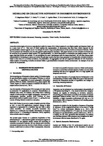
Pedestrian tracking sensor An omnidirectional camera and laser scanner were combined to track pedestrians, as shown in Figure 3. The omnidirectional camera captured a panorama movie. The panorama movie was mainly used to synchronize all position sensor data using pedestrian behavior in manual offline processing. The laser scanner was set at a point 30 cm above the floor. Pedestrian positions were extracted from the temporal laser scanner data using the scene-subtraction methodology.
2.1 Integrated sensor system The sensors listed in Table 1 were integrated to test seamless navigation. We prepared three integrations in our experiments, as follows.
Capture video
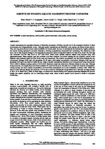
Indoor-outdoor navigation system Signals from satellites GPS, GLONASS, QZSS and IMES were received simultaneously with a DELTA receiver. These signals were then synchronized with GPS time. The receiver is packed in a backpack with an antenna directed vertically, as shown in Figure 1. Position estimation was conducted in offline processing.
Omnidirectional camera
Laser scanner
30 cm Scan pedestrian
Figure 3. Position data acquisition and pedestrian tracking with an omnidirectional camera and laser scanner 2.2 Construction of test environment for indoor-outdoor seamless navigation experiments For the outdoor experiment, we selected an area around our campus, as shown in Figure 4. This area includes parks, highrise buildings, low-rise buildings, stations and wide and narrow roads. For the indoor experiment, we selected a large room in our campus with an outdoor opening, as shown in Figure 5.
Figure 1. Position data acquisition in an indoor-outdoor environment
High-rise buildings
Indoor navigation system A lighting tag receiver, an IMES receiver and an RFID receiver were integrated as an indoor navigation system. These receivers were connected to a mobile PC and were synchronized with the PC time. Two patterns were tested with this system, as shown in Figure 2.
Campus Trajectory
Shopping mall
Stations
Parks
© OpenStreetMap contributors, CC-BY-SA
Figure 4. Study area (outdoor)
4.1m Figure 2. Position data acquisition in an indoor environment
9m Figure 5. Study area (indoor)
36
International Archives of the Photogrammetry, Remote Sensing and Spatial Information Sciences, Volume XXXIX-B4, 2012 XXII ISPRS Congress, 25 August – 01 September 2012, Melbourne, Australia
RFID/Lighting tags(1~22) IMES transmitter(PRN173~PRN175) Measured point(1~221,301~333)
Outside
Y
221
Door PRN174 75 cm 16 301
22
Pedestrian tracker (2)
21
Pedestrian tracker (1)
20
17
317
12
8
4
75cm 13
9
5
19 O
X
Road Glass wall
125 cm
18
50 cm PRN173
50 cm 50 cm
13
75cm
14
10
15
11 200cm
Door
Room 318
6
7
Door 209
3
50cm
2
PRN175
333 1
Metal and glass wall
1
Corridor Door Outside
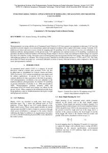
Figure 6. Sensor distribution map for the indoor study area
In the indoor experiment, each sensor was placed in the indoor study area according to our sensor distribution map, shown in Figure 6. Each lighting tag was attached at the center of an inverter light, and was supplied electric power from the inverter, as shown in Figure 7. Each RFID tag was arranged on the floor directly under each lighting tag, as shown in Figure 8. These tags were arranged at 22 points to track pedestrian behavior including walking in a straight line and meandering. Three IMES transmitters with dipole antennae were installed on the ceiling at corners of our test field, as shown in Figure 9. Each IMES transmitter was assigned a Pseudo Random Noise code (173, 174 or 175), and position data were estimated from short identification numbers received from the transmitters. Generally, position data are directly taken from the recorded position data within the tags. However, in this experiment, position data were converted from the identification numbers of the tags.
Figure 8. RFID tags installed on the floor
Figure 9. IMES transmitter installed on the ceiling
Figure 7. Lighting tags installed on the ceiling
37
International Archives of the Photogrammetry, Remote Sensing and Spatial Information Sciences, Volume XXXIX-B4, 2012 XXII ISPRS Congress, 25 August – 01 September 2012, Melbourne, Australia
environments to investigate availability and continuity in an indoor-outdoor navigation environment. The fourth experiment involved outdoor navigation using multiple satellite systems to investigate accuracy, availability and integrity. Based on the results from our experiments, we can make some observations about seamless navigation using multiple navigation systems, focusing on the following representative issues from our research. The first issue is the improvement of availability using multiple navigation systems. We have clarified that outdoor positioning of multiple navigation satellites has the potential to improve availability in an opensky environment. Indeed, compared with the use of GPS only, the use of multiple navigation satellites improved the position fix rate by 20%. On the other hand, we also clarified that in a dense urban environment, the integrity of navigation decreases from 100% to approximately 50% because of multipath interference. In addition, we clarified in our experiment that the position fix rate decreases when the number of navigation satellites increases. The second issue is interference between indoor navigation systems. We found that, because of interference, fewer satellite signals are received by high-sensitivity GPS receivers when an IMES transmitter is located within a 3 m radius of the receiver. Therefore, we conclude that the design of IMES transmitter arrangements should accommodate this restriction in indooroutdoor border areas for seamless navigation using GPS and IMES. The third issue is interference between the indoor navigation and 3D measurement systems. When the orientation of time-offlight infrared camera is within 40° of the line of sight between a lighting tag and a lighting tag receiver, infrared interference renders the lighting tag system unavailable. Therefore, for human sensing and autonomous robot navigation, we must focus on the directional properties of sensors.
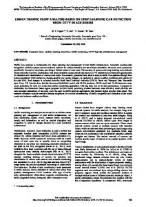
2.3 Results Partial experimental results are as follows. Figure 10 presents one of the results from our outdoor experiment for evaluation of the availability when GNSS receivers including GPS, GLONASS and QZSS are integrated in dense urban areas. Figure 11 shows a result from pedestrian tracking taken from laser scanner data in our indoor experiment. This result was used as a reference value for evaluating the performance of positioning sensors. The accuracy, integrity and continuity of each sensor in our experimental environment are summarized in Table 2 (although we recognize that the performance of sensor system depends on an environment).
Figure 10. A result from the our outdoor experiment
Glass wall Pedestrian trajectory
4. SUMMARY Metal and glass wall
The initial focus in our research was the construction of a test environment for indoor-outdoor seamless navigation experiments. Based on SARPs, we focused on accuracy, availability, continuity and integrity to verify the effects of seamless navigation under a combination of as many systems and sensors as possible. We then conducted data acquisition and data analysis in seamless navigation through four integrated experiments. Based on the results of our experiments, we summarized some observations about seamless navigation using multiple navigation systems.
Figure 11. Result from pedestrian tracking using laser scanner data Table 2. Accuracy, integrity and continuity of each sensor in the experimental environment
IMES Accuracy (Service area) Continuity Integrity
Light tag RFID tag
10m Static 74.67 % Move 83.96 % Static 94.49 % Move 54.15 %
1.5m
0.1m
References
26.38 % 97.70 % 57.30 % 100.00 % 51.46 % 79.75 %
[1] Dinesh Manandhar, Seiya Kawaguchi, Masayuki Uchida, Makoto Ishii, Hideyuki Torimoto. 2008. IMES for Mobile Users Social Implementation and Experiments based on Existing Cellular Phones for Seamless Positioning. In: Proceedings of International Symposium 2008 on GPS-GNSS. [2] S. Kogure, M. Sawabe, and M. Kishimoto. 2006. Status of QZSS Navigation System in Japan. In: Proceedings of ION GNSS 2006, pp. 2092-2102.
3. DISCUSSION The first experiment involved a coarse-resolution indoor navigation using position data taken at 22 points to investigate availability and continuity in an indoor navigation environment. The second experiment involved a fine-resolution indoor navigation using position data taken at 254 points with electric field maps generated from each sensor to investigate accuracy and continuity in an indoor navigation environment. The third experiment integrated navigation of both indoor and outdoor
Acknowledgements This work forms part of a series of experiments conducted by a committee in the Institute of Electrical Engineers of Japan (IEEJ). This work is partly supported by the Strategic Information and Communications R&D Promotion Programme (SCOPE) of the Ministry of Internal Affairs and Communications, Japan.
38