Received May 13, 2015, accepted June 2, 2015, date of publication June 18, 2015, date of current version July 8, 2015. Digital Object Identifier 10.1109/ACCESS.2015.2447014
Secure Hierarchical VPLS Architecture for Provider Provisioned Networks MADHUSANKA LIYANAGE1 , (Student Member, IEEE), MIKA YLIANTTILA1,2 , (Senior Member, IEEE), AND ANDREI GURTOV3,4 , (Senior Member, IEEE) 1 Centre
for Wireless Communication, University of Oulu, Oulu 90014, Finland for Internet Excellence, University of Oulu, Oulu 90014, Finland 3 Helsinki Institute for Information Technology, Aalto University, Espoo 02150, Finland 4 ITMO University, Saint Petersburg 197101, Russia 2 Center
Corresponding author: M. Liyanage (
[email protected].fi) This work was supported in part by the Tekes-Finnish Funding Agency for Innovation, Helsinki, Finland.
ABSTRACT Virtual private LAN service (VPLS) is a Layer 2 virtual private network technique that has gained enormous popularity in industrial networks. However, the deployment of legacy VPLS architectures in large-scale networks is challenging due to unresolved security and scalability issues. In this paper, we propose a novel hierarchical VPLS architecture based on host identity protocol. The proposed architecture tackles both security and scalability issues in legacy VPLS architectures. It secures the VPLS network by delivering vital security features such as authentication, confidentiality, integrity, availability, and secured control protocol. The security analysis and simulation results confirm that the proposed architecture is protected from various IP-based attacks as well. Theoretical analysis and simulation results have also verified that the proposed architecture provides scalability in control, forwarding, and security planes. Finally, the data plane performance of the proposed architecture is measured in a real-world testbed implementation. INDEX TERMS VPLS, VPN, security, scalability, HIP, hierarchical.
I. INTRODUCTION
Network virtualization techniques are widely used in industrial networks to interconnect SCADA (Supervisory Control and Data Acquisition) and process control systems. Usually, the existing premise wide shared networks such as wireless and wired networks are used as the core/provider network of virtualization techniques. It significantly reduces the implementation cost by eliminating the requirement of parallel network infrastructures within in a single factory premise. On the other hand, the legacy control devices are designed for static network environments and they often support only L2 network protocols [1], [2]. As a result, it is challenging or even impossible to use widely used Layer 3 VPN (L3VPN) in industrial networks. As a result, VPLS networks are gaining enormous popularity in industrial networks as an ideal L2 network virtualization techniques to interconnect legacy control devices. VPLS supports L2 Ethernet based multipoint-tomultipoint communication over IP or MPLS (Multiprotocol Label Switching) based core/provider networks. Due to the high-speed connectivity and low cost operation, VPLS networks are now used in many Enterprise applications such
VOLUME 3, 2015
as DCI (data center interconnect), voice over IP (VoIP) and videoconferencing services [3]. However, the utilization of VPLS networks in new application domains is demanding additional requirements such as elevated security and enhanced scalability [4]. Initially, VPLS architectures were proposed as flat architectures [5]–[7]. These flat VPLS architectures are capable enough to build a functional VPLS over small and medium scaled provider networks. The utilization of VPLS networks in large scale networks such as mobile and data center networks requires to interconnect thousands of devices. However, the flat VPLS architectures cannot be deployed in large scale networks due to the scalability limitations in both control and data planes [8]. In such scenarios, the Hierarchical VPLS (H-VPLS) concept provides a viable solution to address the scalability issues [8]–[13]. On the other hand, Internet Engineering Task Force (IETF) specified the security as an indispensable requirement since VPLS networks deliver the customer’s private frames via an untrusted public network [14]. However, the existing hierarchical VPLS architectures are unable to provide a sufficient level of security for a VPLS network. Therefore, it is still
2169-3536 2015 IEEE. Translations and content mining are permitted for academic research only. Personal use is also permitted, but republication/redistribution requires IEEE permission. See http://www.ieee.org/publications_standards/publications/rights/index.html for more information.
967
M. Liyanage et al.: Secure Hierarchical VPLS Architecture for Provider Provisioned Networks
an open issue to provide both VPLS security and scalability simultaneously. Our Contribution: In this paper, we propose a novel hierarchical VPLS architecture based on HIP to overcome both security and scalability limitations. The proposed architecture establishes HIP tunnels between PEs (Provider Edge devices) in hierarchical manner to form the VPLS network. A novel HIP signaling based control protocol is also proposed to manage the operations of the VPLS network. Hence, we name the proposed architecture as Hierarchical HIP enabled virtual private LAN Service (H-HIPLS) (Figure 3). We also propose a novel encrypted label based secure frame forwarding mechanism to transport L2 frames over the hierarchical VPLS network. In contrast to the typical end-to-end operation of the original HIP implementation [15], H-HIPLS architecture uses a ‘‘bump-in-the-wire’’ security mechanism to offer vital security features such as authentication, authorization, confidentiality, integrity, privacy protection, secure control protocol and robustness to the known attacks. On the other hand, H-HIPLS provides the scalability in control, forwarding and security planes. To the best of our knowledge, this is the first secure hierarchical VPLS architecture which provides both security and scalability. Initially, we theoretically analyze the scalability performance of the proposed architecture. Then, we conduct extended simulations to verify that the proposed architecture provides the same level of control and forwarding plane scalability as other non-secured hierarchical VPLS architectures and the same level of security plane scalability as other secure flat VPLS architectures. Furthermore, we analyze the security features of the proposed H-HIPLS architecture and its ability to protect the control protocol from IP based attacks. Finally, the data plane performance of proposed architecture is measured in a real-world testbed implementation and compared the performance with other legacy VPLS architectures. The rest of the article is organized as follows. Section II briefly describes the hierarchical VPLS concept. The proposed H-HIPLS architecture is presented in Section III. Section IV contains the theoretical analysis of the proposed H-HIPLS architecture. The simulation results are illustrated in Section V and VI. The security assessment is presented in Section VII. The testbed implementation and experiment results are discussed in Section VIII. Section IX and X contain the discussion and the conclusion of the article. II. BACKGROUND A. VIRTUAL PRIVATE LAN SERVICE (VPLS)
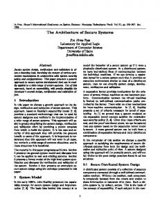
VPLS is a L2VPN service. It provides multipoint-tomultipoint connectivity to extend the Ethernet broadcast domain over geographically dispersed sites. VPLS services are becoming an interesting choice among the enterprise customers since they offer high speed connectivity, any-to-any forwarding at layer 2 and support many enterprise applications. Figure 1 illustrates a simple VPLS network. 968
FIGURE 1. A simple VPLS network.
There are four main components in a VPLS network, i.e. Provider Edge Equipments (PEs), Customer Edge Equipments (CEs), the provider network and the control protocol. A CE device is the intermediate device to interconnect the customer and provider networks. All VPN operations, such as tunnel establishments and address learning functions are running at PEs. A full mesh of Pseudo Wires (PWs)/tunnels are established between these PEs. The provider network is the core/underlay network of VPLS which facilitates above tunnels. It operates as a layer 3 network by using common network protocols such as MPLS or IP. The control protocol is utilized to maintain the proper operation of the VPLS network. It is responsible for all control operations such as auto discovery functions, tunnel establishment, tunnel maintenance, traffic transportation and QoS (Quality of Service) management. B. SCALABILITY ISSUES IN FLAT VPLS ARCHITECTURES
Initially, VPLS architectures were used only for small and medium scale networks. With the evolution of VPLS applications, VPLS networks are now used in large scale networks (e.g. telecommunication networks [16], data center networks [3] and wide area networks [17]) which have thousands of devices. However, VPLS service providers found several scalability issues when they try to deploy flat VPLS architectures in these large scale networks. A flat VPLS architecture requires a PW/tunnel between every pair of PEs. O(N ∗ (N − 1)/2) PWs must be set up for each VPLS network where N is the number of PEs in the provider network. This is called the ‘‘N-square scalability problem’’ and it initiates following scalability issues [9]. First, flat VPLS networks suffer from massive signaling overhead which is required to establish and maintain this massive number of PWs/tunnels. Second, each PE has a maximum limit to support hardware ingress replications and the simultaneous tunnels (e.g. IPsec, HIP and MPLS). If a PE is not able to support N times hardware ingress replications, then a broadcast frame needs to be sent N times over the same network link. It will consume N times the allocated bandwidth. Furthermore, the N th frame has an additional delay of (N −1)∗MTU ∗8/BW where MTU is the Maximum Transmission Unit and BW is the bandwidth of the link. VOLUME 3, 2015
M. Liyanage et al.: Secure Hierarchical VPLS Architecture for Provider Provisioned Networks
It drops the scalability of the forwarding plane. Third, the frame forwarding mechanisms of flat VPLS architectures are also complicated. Every PE should have a global knowledge about the VPLS network to forward the frames through the provider network. Hence, PEs have to facilitate huge forwarding tables and run extensive searching mechanism to find the correct destination address. Fourth, the service provisioning is difficult in a flat architecture. When the VPLS operator needs to interconnect a new customer site by using a new PE, he has to update all the remaining PEs. Moreover, every other PE needs to establish a tunnel with the new PE. The complexity of this service provisioning is increasing exponentially with the number of PEs in the VPLS network. Due to these reasons, present-day VPLS networks are used only to inter-connect maximum of 30 remote sites [17], [18]. C. HIERARCHICAL VIRTUAL PRIVATE LAN SERVICE (H-VPLS)
H-VPLS is the straight-through mechanism to resolve these scalability issues of flat VPLS networks. Basically, H-VPLS reduces the number of PEs which are connected in the full mesh topology. Therefore, H-VPLS requires less number of PWs/tunnels than a flat VPLS network. Figure 2 illustrates a simple H-VPLS architecture.
interfaces which are connected to VPLS network [18]. Generally, these devices do not have any inbuilt security mechanisms to prevent such threats. Therefore, the VPLS network should secure enough to prevents the attacks which are initiated in the provider network [14]. Moreover, the customer private’s data is transported via public, insecure and shared provider network in a VPLS network. However, the legacy H-VPLS architectures support only unencrypted user traffic transportation only. As a result, the customer data are vulnerable to eavesdropping, message modification and reply attacks [18]. The data traffic encryption is mandatory to prevent such attacks. On the other hand, the control channel and signaling data are also vulnerable to security threats at the public network segment of H-VPLS [18]. The most of the H-VPLS architectures [8]–[13] use TCP (Transport Control Protocol) based control protocols (e.g. Border Gateway Protocol (BGP) [5] and Label Distribution Protocol (LDP) [6] based VPLS architectures use TCP sessions) which are vulnerable to several attacks such as DoS (Denial of Service), reset and spoofing attacks [18]. These attacks can jeopardize network resources such as memory space, forwarding tables, network bandwidth and processing power of PEs [17], [18]. Moreover, unencrypted control signaling of H-VPLS architectures is vulnerable to unauthorized modifications which may interrupt the connectivity or alter QoS of network services [18]. Therefore, the control protocol of VPLS architecture should be secured enough to prevent such attacks [14]. Furthermore, the customer data frames should be delivered only via authorized PEs. Hence, a mutual authentication of PEs is required before the exchange of data. Otherwise, the user traffic may direct to a wrong location and a malicious user can retrieve or destroy the valuable data [18]. However, the legacy H-VPLS architectures do not support any authentication and authorization mechanisms. E. HOST IDENTITY PROTOCOL (HIP)
FIGURE 2. A simple H-VPLS architecture.
H-VPLS contains two types of PEs as u-PE and n-PE [8]. u-PEs are user facing PEs, while n-PEs are network facing PEs. A n-PE runs the key role in VPLS as it has all the intelligence of the VPLS architecture. Specifically, it is responsible for packet forwarding, address learning and auto discovery functions. An u-PE has an aggregation role and it simply forwards all the packets to the next n-PE. D. SECURITY CONSIDERATIONS OF HIERARCHICAL VPLS ARCHITECTURES
A VPLS network interconnects legacy L2 control devices. Usually, these devices reside in the private network segments which are physically protected. However, the interconnection of legacy devices via public provider network will expose them to a wide range of security threats. For instance, legacy devices are vulnerable to attacks through their network VOLUME 3, 2015
HIP is a new security and mobility protocol which had standardized by IETF [19]. Generally, an IP address has a dual role as the host and location identifiers. HIP separates the dual role of IP address by introducing a new layer to TCP/IP layered model [19]. Each HIP host stores a public/private key pair. HIP architecture proposed to use a cryptographic host identifier (i.e. the public key) which is called Host Identity (HI) as the identifier of the device. Then, all occurrences of IP addresses in applications are eliminated. They are replaced with 128-bit hash of HI which is called Host Identity Tag (HIT). Moreover, HIP recommends to establish HIP tunnel between communicating devices. HIP BEX (Base Exchange) [19] is the initial handshake procedure which establishes HIP tunnels between communicating devices. III. THE PROPOSED VPLS ARCHITECTURE
In this paper, we propose a secure H-VPLS architecture based on HIP to provide the demanded level of security and 969
M. Liyanage et al.: Secure Hierarchical VPLS Architecture for Provider Provisioned Networks
FIGURE 3. The protocol stack of the proposed H-HIPLS architecture.
scalability for a VPLS network. Basically, H-HIPLS proposes to establish HIP tunnels between PEs in a hierarchical manner (Figure 3). We propose a novel encrypted label based forwarding mechanism to facilitate the secure frame forwarding in this hierarchical architecture. H-HIPLS also proposes a dynamic address learning mechanism, a hierarchical SME (Security Management Entity) topology and a session key mechanism to facilitate the rest of the operations in the H-VPLS network. Figure 5 illustrates the protocol stack of the proposed H-HIPLS architecture. The operation of proposed H-HIPLS architecture is described in six sections as control protocol, provider VPNs, PE management, packet forwarding mechanism, address learning mechanism and key management.
traffic priorities and QoS classes [16]. According to the Service Level Agreements (SLAs) with each customer, the provider classifies the customer traffic into corresponding provider VPNs. However, the number of VPNs used in the provider network is very limited. For instance, a mobile backhaul network supports 3-5 provider VPNs [16]. In industrial networks, most of the provider networks support only one provider VPN [17]. However, the service provider has the flexibility to define the number of provider VPNs in the VPLS network. For instance, the control VPN of H-HIPLS is a provider VPN which transport control and signaling data.
A. CONTROL PROTOCOL
The very first task of a newly added unregistered PE is to be registered with the VPLS network. We use a SME (Security Management Entity) to facilitate the registration process of new PEs. Proposed H-HIPLS architecture uses SME for two tasks. 1) Authorization of unregistered PEs based on Access Control Lists (ACLs) 2) Security key management (see Section III-G). We propose a novel PE registration procedure based on HIP. During this registration procedure, new PEs are authenticated based on a Public Key Infrastructure (PKI) and authorized according to ACLs. Figure 4 illustrates the PE registration procedure. Here, the initiator and responder respectively represent the unregistered newly added PE and SME.
The control protocol is the heart of the VPLS network. It is mainly responsible for tunnel establishment, address learning and key management functions. The secure operation of the control protocol is mandatory to maintain the proper operation of the VPLS network [14]. The H-HIPLS proposes a secure control protocol based on HIP signaling. Basically, we define a separate provider VPN as the control VPN to securely transport the control and signaling data. The separation of control plane traffic is motivated by several reasons. First, the control data frames require higher priority and higher QoS than user data frames. A VPN based traffic separation is an ideal mechanism to provide such services for the control traffic [16]. Second, the implementation of extra security mechanism for the control data is possible with the existence of a separate control VPN. Specifically, strong access control, firewalls and Deep Packet Inspection (DPI) mechanisms can be implemented on control VPN traffic to avoid intruder attacks on the control plane.
C. PE MANAGEMENT 1) PE REGISTRATION
B. PROVIDER VPNs
Similar to other provider networks such as mobile networks and Internet Service Providers (ISPs), we propose to use provider VPNs to support traffic clarification in H-HIPLS. In provider networks, the service provider maintains a small set of VPN classes (provider VPNs) based of different service factors such as supported data rates, 970
FIGURE 4. PE registration procedure.
The first message (I1) triggers the registration procedure. It contains HITs of the initiator and responder. SME does VOLUME 3, 2015
M. Liyanage et al.: Secure Hierarchical VPLS Architecture for Provider Provisioned Networks
not allocate any resources for the new PE at the arrival of I1 message. It is a safety mechanism to avoid DoS attacks. However, SME sends a pre-generated R1 message for the PE. It contains a cryptographic puzzle, Diffie-Hellman (D-H) key parameters, the public key of SME, the sequence number and a signature. SME includes its D-H key parameters to generate a symmetric key which is later used as KEK (Key Encryption Key) of PE. R1 message also contains HI or the public key of SME. It is used by the PE to verify the signature of the R1 message. Finally, the signature is used to verify the integrity of the R1 message. It is generated over the R1 message by using SME’s private key. The initiator sends I2 message after the arrival of R1 message. It contains the solution of the puzzle, D-H key parameters, the public key of PE, the sequence number and a signature. I2 message has similar obligatory fields as R1. However, the PE includes the solution of the puzzle as the puzzle parameter in R2. Finally, the signature is generated over I2 message by using the PE’s private key. Upon the arrival of I2 message, SME subsequently checks the signature and the solution of the puzzle. Furthermore, the identity of the PE is verified after the arrival of I2 message. Then, SME checks ACLs to authorize the new PE. If the PE is a legitimate node and passes all the verification procedures, SME completes the authentication phase by sending the R2 message. Otherwise, SME will drop the authentication request. R2 message contains a CEK (Content Encryption Key), a certificate, the sequence number and a signature. The certificate contains an authorization token (AUTH-Token), configuration information for the new PE and other VPLS management data. It is encrypted by KEK to protect the integrity and confidentiality. The authorization token is used to establish the HIP tunnels with PEs to forward data frames. The CEK field contains CEK of the control VPN. 2) THE REMOVAL OF PEs
It is also necessary to remove inactive PEs for the efficient operation of VPLS. H-HIPLS uses both active and passive notifications to remove the inactive PEs. In an active notification mechanism, PEs will actively notify their departure to SME before they leave the VPLS network. In passive notification mechanism, SME learns the departure of a PE by a failure to acknowledge a periodic CEK distribution. D. TUNNEL ESTABLISHMENT
According to the proposed H-HIPLS architecture, HIP tunnel establishment is mandatory between PEs before any type of data transfer. We propose a novel tunnel establishment procedure based on the HIP BEX to establish these HIP tunnels. Figure 5 illustrates the tunnel establishment procedure. The message exchanges of the proposed tunnel establishment procedure are almost similar to the message exchanges of the previous PE registration procedure. Furthermore, the functions of obligatory fields in both procedures are the same. However, there are two notable differences. VOLUME 3, 2015
FIGURE 5. The tunnel establishment procedure.
First, the tunnel establishment procedure evades the D-H key exchange. Therefore, R1 and I2 messages do not contain any D-H key exchange fields. Second, we propose to exchange an authentication token during this tunnel establishment procedure. It prevents the tunnel establishments with unauthorized users. The authentication token is generated as follows; Authentication token = ECEK (AUTH -Token||HI ) Each PE concatenates AUTH-Token which is received from the SME with its HI and encrypts it using CEK of the control VPN to generate the authentication token. The end users exchange their authentication tokens in I2 and R2 messages. The receiver of the authentication token decrypts the token and checks the respective fields by mapping with its own data. Unauthorized users cannot provide a correct authentication token since they do not have a valid AUTH-Token. Hence, the connection requests with invalid authentication tokens are rejected. E. PACKET FORWARDING MECHANISM
We propose a novel encrypted label based packet forwarding mechanism and this section describes the proposal. When a u-PE receives a data frame from a CE, it follows three steps. In the first step, u-PE checks for an existing HIP tunnel with n-PE. If there is no HIP tunnel, u-PE establishes a HIP tunnel with the relevant n-PE. In the second step, the source u-PE encrypts L2 frame using the corresponding CEK of the provider VPN. Then, it will wrap within the ESP payload. In the third step, the source u-PE inserts the encrypted label into the standard ESP header of the packet and forwards the frame to the n-PE. Figure 6 illustrates a modified ESP header. The encrypted label is the encrypted destination MAC (Media Access Control) address of the frame. It encrypts by using CEK of the control VPN. When an u-PE receives a data frame from a n-PE, the u-PE removes upper layer headers including the ESP header and decrypts the ESP payload using the corresponding CEK of the provider VPN. Then it will transmit to the customer access network as a L2 frame. When a n-PE receives a data frame, it follows two steps. First, it decrypts the encrypted label and checks the MAC-PE mapping table for the next hop to forward the packet. The MAC-PE mapping table is the forwarding table of the VPLS which uses to map the destination MAC address of 971
M. Liyanage et al.: Secure Hierarchical VPLS Architecture for Provider Provisioned Networks
encrypt all data frames which are belong to that VPN. The KEK is unique to a single PE and it is used to encrypt/decrypt the corresponding CEKs, certificates and any other control information. SME is the heart of the key management system. It involves main key management functions, namely key generation and distribution. 1) KEK GENERATION AND DISTRIBUTION
FIGURE 6. The Modified ESP Header.
Each PE shares a unique KEK with SME. KEK is a symmetric key which is shared during the initial PE registration procedure. The D-H key exchange is utilized to exchange this key (see Figure 4). However, each KEK has a life time. Initially, we define the life time of a KEK as 15 minutes. However, the network operator can change the life time according to his security specifications. SME deletes KEKs after the expiration of the life time. We propose a novel key update procedure to update KEK after the expiration. Figure 7 illustrates the KEK update procedure.
the data frame to the network address of next hop PE. Second, it checks for an existing HIP tunnel between the next PE. If there is no HIP tunnel, it establishes a new tunnel. Then, it forwards the frame to the next PE. F. ADDRESS LEARNING MECHANISM
Since VPLS is a L2VPN solution, it forwards frames based on MAC addresses. On the other hand, each u-PE is responsible for a certain set of customer devices. Hence, the frames should be delivered over the provider network to reach the correct PE which is responsible for the destination device. However, the underlay provider network is a L3 network. Therefore, it is needed to map the destination MAC address of the device to the network address of the corresponding PE. We propose to maintain a dynamic MAC-PE mapping table in each n-PE to accomplice this requirement. Each n-PE updates their MAC-PE mapping table by using two address learning instances, namely u-PE advertisements and dynamic address requests. In the first case, each u-PE advertises MAC addresses of the responsible devices to directly connected n-PEs. Based on these advertisements, n-PEs update their MAC-PE tables. When a n-PE receives a frame with an unknown destination MAC, the n-PE broadcasts an encrypted address request frame (a.k.a. Dynamic Address Request) to all the other PEs to identify the responsible PE. These requests are encrypted using CEK of the control VPN. Then, the responsible PE will send an encrypted unicast frame as a reply. Based on the reply, the requested PE updates its MAC-PE mapping table. G. KEY MANAGEMENT
The proposed H-HIPLS architecture uses a session key mechanism instead of per tunnel key mechanism which is proposed in classical HIP implementation [19], [20]. Similar to [21] and [22], we propose to use two key types as Content Encryption Key (CEK) and Key Encryption Key (KEK). A CEK is unique to a single provider VPN and it is used to 972
FIGURE 7. KEK update procedure.
KEK update procedure has only two messages. It evades the mutual authentication phase since registered PEs already have an established HIP tunnel. Both I1 and R1 messages have a similar format as the R2 message of the previous tunnel establishment procedure. Once KEK is expired, PE starts KEK update procedure. R1 message contains a SEQ parameter. It is increasing by one for each message. Furthermore, I1 contains the PE’s D-H key parameters. SME replies the I1 message with a R1 message. It contains SME’s D-H key parameters and the acknowledgment for the received I1 message. Based on these D-H key parameters, both SME and PE regenerate new KEK. 2) CEK GENERATION AND DISTRIBUTION
SME periodically generates CEKs and securely distributes to each PE. Before the transportation, these CEKs are encrypted by using KEK of each PE. Similar to KEKs, each CEK has a life time. SME generates new CEKs after the expiration of the life time. Apart from that, there are two possible CEK generation instances available to protect the forward and backward confidentiality. Figure 8 illustrates the CEK update procedure. CEK update procedure also has only two messages. SME initiates CEK update procedure. It also evades the mutual authentication phase since registered PEs have already established HIP tunnels. Both I1 and R1 messages have a similar format as the previous KEK update procedure. However, the R1 message delivers CEKs. All these CEKs are encrypted by using KEK of corresponding PE. VOLUME 3, 2015
M. Liyanage et al.: Secure Hierarchical VPLS Architecture for Provider Provisioned Networks
TABLE 1. The number of tunnels/PWs in the VPLS network.
responsible for u-PE1 to u-PE5. n-SMEs are responsible for a group of n-PEs and u-SMEs which are residing in a section of the VPLS. For instance, n-SME1 is responsible for n-PE1 and u-SME1. Finally, all n-SMEs are mesh connected to exchange the information rapidly. FIGURE 8. The CEK update procedure.
3) SME TOPOLOGY
We propose a distributed SME topology due to three reasons. First, a distributed topology eliminates the single point of failure by increasing the number of SMEs. Second, a distributed topology reduces the PE registration and key distribution delays. We can keep local SME near to PEs to reduce the communication latency. Third, a distributed topology reduces the security management work load. A single SME utilization for a large scale network is not practical. In such networks, SME has to maintain thousands of HIP tunnel statuses and support key management functions for thousands of PEs. Thus, single SME utilization will increase the delay of processing security requests and cost of a SME. Ultimately, it will limit the scalability of H-HIPLS. Therefore, a hierarchical SME topology is proposed in H-HIPLS architecture and it is illustrated in Figure 9.
IV. NUMERICALLY ANALYZE
In this section, we numerically analyze the scalability of the proposed H-HIPLS architecture. Since there are no secure hierarchical VPLS architectures, we compare the performance of our proposal with both secure flat VPLS architectures namely HIPLS [20], S-HIPLS [21], [22] and the widely use non secure H-VPLS architecture, i.e. LDP based H-VPLS(H-LDP) [6]. We use the following notation. Number of connected customer site in VPLS network = N Number of u-PEs in the network = N Number of n-PEs in the network = Nn Number of Provider VPNs in the network = M The considered VPLS network interconnects N customer sites with N PEs/u-PEs. H-VPLS architectures use extra Nn n-PEs to form the hierarchical architecture. A. CONTROL PLANE SCALABILITY
The number of tunnels/PWs in the VPLS network is a key parameter to compare the control plane scalability. The control data overhead for tunnel establishments, tunnel maintenance and topology update events can be reduced by minimizing the number of PWs in the network. Thus, the number of tunnels/PWs in the network is inversely proportional to the control plane scalability. Table 1 contains tunnels/PWs requirements for each VPLS architecture. H-HIPLS has less or equal number of tunnels in the network than HIPLS and S-HIPLS architectures under the following condition. N Nn (N + 1) ≥ (Nn + 1) + 2N 2 2 Nn + 1 N for N > 3 ≥ Nn N −3
FIGURE 9. Hierarchical SME Tology.
Here, u-SMEs are responsible for a group of u-PEs which are residing in a section of VPLS. For instance, u-SME1 is VOLUME 3, 2015
(1) (2)
In large scale networks, N > Nn . Therefore, RHS of equation 2 is below 1 while LHS is above 1. Hence, H-HIPLS always has less or equal number of tunnels per PE and in the network than HIPLS and S-HIPLS architectures in large scale networks. 973
M. Liyanage et al.: Secure Hierarchical VPLS Architecture for Provider Provisioned Networks
TABLE 2. The key storage requirement of the VPLS network.
TABLE 3. The efficiency of the broadcast mechanism.
On the other hand, H-HIPLS increases the number of tunnels in the network by N than non-secure H-LDP architecture due to extra tunnel establishments with SME. Thus, H-HIPLS significantly improves the scalability of control plane than secure VPLS architectures and provides the slightly deficient performance than existing non-secure hierarchical VPLS architectures. B. SECURITY PLANE SCALABILITY
The key storage requirement is a main parameter to compare the scalability of the security plane. If a PE needs to store a large number of keys, it uses the already scarce memory space of a PE which can be used for other functions such as forwarding tables, filters and frame buffering. On the other hand, a large number of keys can cause extensive key searches. Such procedures use extra processing power and increase the encryption delay. We evaluate the key storage requirement at different entities of the VPLS network for HIPLS, S-HIPLS and our H-HIPLS architectures. Table 2 contains the key storage requirement of each VPLS architecture. H-HIPLS stores less or equal number of keys in the network than HIPLS architecture under the following condition. N (N + 1) ≥ N (M + 2) + M + 3Nn 3Nn + M ) N ≥ M +1+( N
(3) (4)
In large scale networks where N > M , Nn , condition of equation 4 is true. On the other hand, H-HIPLS network stores extra 3Nn of keys S-HIPLS architecture due to the additional n-PEs. However, most of these keys are stored in newly added n-PEs. Therefore, H-HIPLS will store the same number of keys per PE as S-HIPLS. Thus, H-HIPLS significantly improves the scalability of security plane than HIPLS and provides the slightly deficient performance than S-HIPLS. 974
C. FORWARDING PLANE SCALABILITY
An efficient broadcast mechanism is a key requirement to enhance the scalability of the forwarding plane. Table 3 contains the performance of the broadcast mechanism of each VPLS architecture. H-HIPLS always decreases the number of encryption per broadcast frame (EFrame ) at a PE than HIPLS architecture. Furthermore, it has the same performance as S-HIPLS. The maximum number of broadcast frame replications at a PE (LPE ) is lower in H-HIPLS than HIPLS and S-HIPLS architectures under the following condition. N−
N ≥ Nn − 1 Nn N ≥ Nn for N > 1
(5) (6)
Above condition are also always true since N > Nn for large scale networks. Hence, H-HIPLS reduces the maximum number of broadcast frame replications at a PE than HIPLS and S-HIPLS architectures. Furthermore, H-HIPLS has the same performance as H-LDP. Thus, H-HIPLS significantly improves the scalability of forwarding plane than secure VPLS architectures and provides similar performance as existing non-secure hierarchical VPLS architectures. V. ANALYSIS OF THE SCALABILITY
The proposed H-HIPLS architecture is simulated on OMNET++ and evaluated the performance of scalability. We compare the performance of our proposal HIPLS [20], S-HIPLS [21] and H-LDP [6] architectures. A network of 125 nodes is used as the simulation model. The model network (Figure 10) is generated by using stochastic Kronecker graphs [23]. Among these nodes, 100 nodes are randomly selected as PE nodes and the rest of the nodes act as provider routers. The tunnels between PEs are established based on the relevant VPLS architecture. Each VPLS network uses to interconnect 100 user VOLUME 3, 2015
M. Liyanage et al.: Secure Hierarchical VPLS Architecture for Provider Provisioned Networks
FIGURE 10. The simulation model.
devices. The customer L2 devices are uniformly attached to PEs/u-PEs. We add 10 extra n-PEs for hierarchical VPLS models, i.e. H-LDP and H-HIPLS. Maximum of 10 u-PEs are connected to each n-PE. It is equal to the number of 10 Gbps ports support by the Cisco ASR 9001 PE router [24]. We assume a scenario where each L2 device has to send average of 25 files for randomly selected L2 devices. Each device randomly selects a user device in the network to send a file and continues this process until the end of file queue. The network bandwidth at the provider network is set to 100 Mbps. We change file sizes according to the Pareto distribution with the minimum file size of 4.5 KBytes and to the maximum size of 20 MBytes [25]. Each simulation is conducted for 20 times. We measure the evaluation metrics at the end of each test and average values are presented here.
tunnel per PE for the secure key exchange with SME. On the other hand, the total number of tunnel requirement in the network is exponentially increasing with the number of PEs for both HIPLS and S-HIPLS. Therefore, the experiment results verify that the tunnel establishment complexity of the proposed H-HIPLS is significantly lower than other secured architectures i.e. HIPLS and S-HIPLS. H-HIPLS also offers almost similar performance as other hierarchical architectures such as H-LDP. These simulation results match with the previous numerical analysis as well. Hence, we can conclude that the H-HIPLS significantly improves the scalability of control plane than other secure VPLS architectures and provides the similar performance as the existing non-secure hierarchical VPLS architectures. B. COMPARISON OF THE SECURITY PLANE SCALABILITY
The key storage requirement is one of the main metrics to measure the security plane scalability. Therefore, we evaluate the key storage requirement at different entities of the VPLS network for HIPLS, S-HIPLS and H-HIPLS architectures. 1) KEY STORAGE AT A PE
The key storage complexity at a PE against the number of PEs is illustrated in Figure 12. The number of provider VPNs is set to 5 [16] and the number of PEs is changed from 1 to 100.
A. COMPARISON OF THE CONTROL PLANE SCALABILITY 1) TOTAL NUMBER OF TUNNELS IN THE NETWORK
Figure 11 illustrates the total tunnel establishment complexity of the VPLS network against the number of PEs.
FIGURE 12. The number of keys stored at a PE against PEs.
FIGURE 11. The total number of VPN tunnels in the Network.
A significant reduction in the total number of tunnels in hierarchical architectures is observed in compare with flat architectures. There is a linear increment in the total number of tunnels with the number of PEs for both H-LDP and proposed H-HIPLS. Comparably, H-LDP has slightly better performance than H-HIPLS since H-HIPLS needs an extra VOLUME 3, 2015
The simulation result indicates a linear increment in the total number of keys stored at a PE with the number of PEs for HIPLS. Both S-HIPLS and H-HIPLS (only for u-PE) have similar performance and the number of keys stored at a PE remains constant. Hence, the number of keys stored at a PE is independent of the number of PEs for both S-HIPLS and H-HIPLS. Furthermore, n-PE of H-HIPLS has the minimum key storage requirement as it stores only CEK of control VPN and its own KEK. 2) KEY STORAGE IN THE AUTHENTICATION SERVER (AS)/ SECURITY MANAGEMENT ENTITY (SME)
The key storage complexity in AS/SME against the number of PEs is illustrated in Figure 13. The number of provider VPNs 975
M. Liyanage et al.: Secure Hierarchical VPLS Architecture for Provider Provisioned Networks
S-HIPLS and H-HIPLS have almost similar performance and the number of keys stored in the network is linearly increasing with the number of PEs. The experiment results clearly show that the key storage requirement in the proposed H-HIPLS is significantly lower than HIPLS and slightly higher than S-HIPLS. These simulation results match with the previous numerical analysis as well. Hence, we can conclude that H-HIPLS significantly improves the security plane scalability then HIPLS and provides the similar performance as S-HIPLS. C. COMPARISON OF THE FORWARDING PLANE SCALABILITY FIGURE 13. The number of keys stored at the AS/SME against PEs.
is set to 5 [16] and the number of PEs is changed from 1 to 100. The simulation results indicates a linear increment in the total number of keys stored at AS/SME with the number of PEs for all three scenarios. However, the number of keys stored at a SME in H-HIPLS is slightly higher than HIPLS and S-HIPLS. The number of keys stored at AS for HIPLS only depends on the number of PEs in the network. However, the number of keys stored at SME for S-HIPLS and H-HIPLS architectures depends on both the number of PEs and VPNs in the network. In addition, the number of n-PEs in the network is also effecting the performance of H-HIPLS. However, this deficiency in H-HIPLS can be minimized by using the proposed distributed SME topology.
Each PE has a maximum limit to support hardware ingress replications and simultaneous tunnels. It limits the forwarding plane scalability. On the other hand, an efficient broadcast mechanism is also a key requirement to improve the scalability of forwarding plane. Hence, the performance of the frame broadcasting mechanism and the number of tunnels per PE in different architectures have been compared. 1) NUMBER OF TUNNEL REQUIREMENT PER PE
We illustrate the total tunnel establishment complexity of a PE against the number of PEs in Figure 15. Here the number of PEs is changed from 1 to 100.
3) TOTAL KEY STORAGE IN THE NETWORK
Figure 14 illustrates the total key storage complexity of the VPLS network against the number of PEs. Here also, the number of provider VPNs is set to 5 [16] and the number of PEs is changed from 1 to 100.
FIGURE 15. The number of tunnels per PE.
FIGURE 14. The total number of keys stored in the VPLS network against PEs.
We observe an exponential increment in the total number of key stored in the network with the number of PEs for HIPLS. 976
The simulation results indicate a significant reduction in the number of tunnels per PE in hierarchical architectures compared with flat architectures. There is a staircase-like linear increment in the number of tunnels per n-PE with the number of PEs for both H-LDP and proposed H-HIPLS. Furthermore, the number of tunnels per u-PE remains constant for both H-LDP and H-HIPLS as it is independent of the number of PEs. Comparably, H-LDP has slightly better performance than the proposed H-HIPLS since each PE in a H-HIPLS needs an extra tunnel for the secure key exchange. On the other hand, the number of tunnels per PE is linearly increasing with the number of PEs for both HIPLS and S-HIPLS. VOLUME 3, 2015
M. Liyanage et al.: Secure Hierarchical VPLS Architecture for Provider Provisioned Networks
2) THE MAXIMUM NUMBER OF ENCRYPTION PER BROADCAST FRAME AT A PE
We inject a single broadcast frame that should be delivered to all PEs in the network. We measure the number of encryptions at each PE. Figure 16 illustrates the maximum number of encryption per broadcast frame at a PE for each VPLS architecture.
HIPLS and S-HIPLS. A significant reduction in the maximum number of broadcast frame replications at a PE is observed in hierarchical architectures compared with flat architectures. Furthermore, only n-PEs replicate the broadcast frames in H-HIPLS while all the PEs do so in HIPLS and S-HIPLS architectures. The simulation results verify that the workload of broadcast replication at a PE and the number of tunnels per PE in H-HIPLS are significantly lower than other secure VPLS architectures. Moreover, H-HIPLS has similar performance as H-LDP. These simulation results match with the previous numerical analysis as well. Hence, we can conclude that H-HIPLS significantly improves the forwarding plane scalability than secure VPLS architectures and provides the similar performance as the existing non-secure hierarchical VPLS architectures. VI. IP BASED ATTACK PROTECTION
FIGURE 16. The maximum number of encryptions per broadcast frame.
We can see a linear increment in the number of encryptions per broadcast frame at a PE with the number of PEs. However, the number of encryptions of both S-HIPLS and H-HIPLS remains constant at 1. 3) THE MAXIMUM NUMBER OF BROADCAST FRAME REPLICATIONS AT A PE
Each broadcast frame needs to be replicated at intermediate PEs to deliver it to all PEs in the network. We measure the number of replications at each PE. Figure 17 shows the maximum number of broadcast frame replications at a PE for each VPLS architecture.
FIGURE 17. The maximum number of replications per broadcast frame.
There is a linear increment in the maximum number of broadcast frame replications at a PE for both VOLUME 3, 2015
The control protocol is the heart of the VPLS network. Hence, it should be protected from potential attacks. We compare the impact of IP based attacks on the control protocol of the proposed architecture. We use H-LDP [6], HIPLS [20] and S-HIPLS [21] architectures as the reference models to compare the performance under TCP SYN DoS, TCP SYN DDoS and TCP reset attacks. A. THE IMPACT OF ATTACKS ON TUNNEL ESTABLISHMENT PHASE 1) THE IMPACT OF TCP SYN DoS ATTACK
In a TCP SYN DoS attack, an attacker sends excessive amount of TCP SYN packets to the target server. The server allocates a TCP port for each successfully arrived TCP SYN packet and reserves it for a certain time period (TCP timeout). Such a way, the attacker captures all ports in the server [26]. Then, the server will stop responding to the legitimate user traffic. We use the same simulation model which was presented in [21]. It has a VPLS network with 300 nodes. The bandwidth of the network is 100 Mbps. The attacker also has the same bandwidth of 100 Mbps. The number of TCP ports per user is set to 64000 and the TCP timeout is set to 270 s [26]. The simulation runs for 500 s and the attacker sends the fake TCP SYN packets during 25 s - 75 s time interval for a single user node. We measure the packet drop at the user node and Figure 18 illustrates the percentage packet drop over the simulation time. HIPLS, S-HIPLS and the proposed H-HIPLS have similar performance under the TCP SYN DoS attack. These architectures have almost zero packet drop for the whole simulation period. However, the H-LDP lost almost all the packets during the attack period. Although the attack lasts for 50 s, H-LDP architecture requires additional 270 s (a TCP timeout period) to fully recover from the attack. The simulation results verify that the control protocol of the proposed H-HIPLS is secured from TCP SYN DoS attacks. 977
M. Liyanage et al.: Secure Hierarchical VPLS Architecture for Provider Provisioned Networks
Thus, simulation results verify that the control protocol of the proposed H-HIPLS is secured from TCP SYN DDoS attacks as well. B. THE IMPACT OF ATTACKS ON DATA TRANSPORT PHASE 1) THE IMPACT OF TCP RESET ATTACK
FIGURE 18. The impact of TCP SYN DoS attack.
2) THE IMPACT OF TCP SYN DDoS ATTACK
The TCP SYN DoS attack is also simulated. A coordinated DDoS attack scenario is used here. We use the similar simulation setup which is used to simulate the TCP SYN DoS attack. The number of attackers is gradually increased from 1 to 20. We measure the total time required to successfully attack a single user node in the VPLS network for each architecture, namely H-LDP, HIPLS, S-HIPLS and H-HIPLS. The simulation duration is 500 s for each simulation and attackers send bogus TCP SYN packets throughout the whole simulation duration. The simulation is conducted for 10 times and the average time required to successfully attack the user node is presented in Figure 19.
A TCP reset attack can terminate an ongoing TCP connection between two users by injecting the fake TCP packets to the network. An attacker eavesdrops the TCP connection and collects the TCP header information. Later, this information is used to generate fake TCP packets. The attacker sets the ‘‘Reset Bit’’ to ‘‘1’’ in these TCP packets. Usually, the ‘‘Reset Bit’’ is used to indicate unexpected failures on either side of the TCP connection and it requests to reset the connection. Since typical end users have no mechanism to identify these fake TCP packets, end users terminate the TCP connection upon the arrival of fake TCP packets [27]. We evaluate the impact of TCP reset attack on the proposed H-HIPLS architecture and compare the performance with H-LDP, HIPLS and S-HIPLS. We use the same simulation setup which is used to evaluate the impact of TCP SYN DoS attack. Figure 20 illustrates the probability of a successful attack against the size of files. We change the size of files according to the Pareto distribution with the minimum file size of 4.5 KBytes and to the maximum size of 20 MBytes [25].
FIGURE 20. The impact of TCP reset attack.
FIGURE 19. The impact of TCP SYN DDoS attack.
The average time required to successfully attack all three secure VPLS architectures has remained in the initial value (zero) at the end of each simulation. It verifies that there is no impact of DDoS attack on HIPLS, S-HIPLS and H-HIPLS. However, H-LDP is vulnerable for DDoS attacks as well. The average time required to successfully attack H-LDP is decreasing with the number of attackers. 978
We observe that the probability to successfully attack the H-LDP architecture is increasing with the file size. The attacker gets more time to reset the connection due to the longer transmission delay of larger files. On the other hand, HIPLS, S-HIPLS and the proposed H-HIPLS have a zero probability of a successful attack. Hence, it verifies that the control protocol of the proposed H-HIPLS is secured from TCP reset attacks. VII. SECURITY ANALYSIS
In this section, we analyze the security performance of proposed H-HIPLS architecture. VOLUME 3, 2015
M. Liyanage et al.: Secure Hierarchical VPLS Architecture for Provider Provisioned Networks
A. PROTECTION AGAINST DoS ATTACKS
Various DoS attacks scenarios are possible in a VPLS network. DoS attacks are very critical since it effects both control and user plane traffic. Most of VPLS DoS attacks are happening at the tunnel establishment phase where the attacker sends excessive amount of bogus connection requests to PEs [18]. However, the H-HIPLS architecture proposes to establish a HIP tunnel before any data communication. Therefore, the attacker tries to send a lot of I1 messages (Figure 4 and 5) to perform a DoS attack. However, the responder does not allocate any server resources for upcoming connection request. It just sends a precomputed R1 message for each I1 message. This R1 message contains a cryptographic puzzle to increase the commitment from the initiator. The responder only allocates the server resources after the arrival of I2 message with a correct solution for the puzzle. Therefore, the H-HIPLS architecture is protected from DoS attacks. B. PROTECTION AGAINST REPLAY ATTACKS
Both control and user planes of a VPLS network are vulnerable to replay attacks on various scenarios. For instance, the tunnel establishment phase, the key update phases in the control plane and data communication sessions in the user plane. The H-HIPLS architecture proposes the following mechanisms to replay attacks during tunnel establishment phase. The responder sends a virtue of the stateless response to I1 messages with pre-calculated R1 messages. It not only protects the responder against DoS attacks, but also replay attacks based on I1 messages. A monotonically increasing ‘‘Generation counters’’ are included in R1, I2 and R2 messages. These counters protects the intiator from R1 and R2 based replay attacks and the responder from I2 based replay attacks. The key exchange messages are transported over the existing HIP tunnels. HIP tunnels uses IPsec ESP (Encapsulating Security Payload) mode for data communication. IPsec ESP mode utilizes sequence numbers to protect messages against replay attacks. Thus, the key exchange messages are automatically protected from replay attacks. HIP tunnels are used for data communication over the VPLS network. Thus, the sequence numbers mechanism which is used by IPsec ESP mode, protects the user data frames against the replay attacks. Thus, the attacker’s replays of IPSec encrypted packet will be rejected due to sequence number mismatches at end users. C. PROTECTION AGAINST IP SPOOFING ATTACKS
IP spoofing attacks are very common in IP based networks where the attackers impersonate as legitimate users by spoofing their IP addresses. Proposed mutual authentication mechanism in H-HIPLS uses Host Identity (A cryptographic key) to prove the identity of the user. Thus, the proposed mutual authentication mechanism is capable to verifying the identity VOLUME 3, 2015
of the entity behind the IP address and it prevents IP spoofing attacks. D. PROTECTION AGAINST EAVESDROPPING ATTACKS
The customer data which are transmitted over the provider network are vulnerable to eavesdropping attacks. There are two types of eavesdropping attacks namely passive and active attacks. In a passive attack, the attackers try to read the ongoing customer data to capture important user information. However, VPLS traffic of H-HIPLS architecture is encrypted by using CEKs. These keys are available only for the legitimate PEs and updated in timely manner. An intruder cannot obtain a CEK without being authorized and authenticated by SME. Both authorization and authentication phases enrich of a wide range of security features to prevent such spoofing attacks. Without a CEK, attackers can not eavesdrop the communication data. Thus, user traffic in H-HIPLS network is protected from passive attacks. In an active attack, attackers eavesdrop the ongoing communication channels and use the eavesdropped network information to perform various attacks such as IP spoofing, TCP reset and replay attacks. However, proposed architecture uses HIP tunnels (IPsec BEET) in ESP mode for the data communication. Thus, the original IP headers, TCP headers and payload are always encrypted. It prevents possible active eavesdropping attacks. E. PROTECTION OF SECURITY MANAGEMENT ENTITY (SME)
SME is the responsible element for security function in the VPLS network. It accepts only IPsec ESP packets which send through a HIP tunnel. Hence, a potential attacker has to establish a HIP tunnel with SME before send/receive the data. However, the HIP tunnel establishment follows a HIP BEX based security procedure which not only authenticates the device based on PKI mechanism but also authorizes based on ACLs. In [28], authors claimed that HI based authentication in HIP BEX is sufficient enough to avoid spoofing attacks. On the other hand, the inbuilt puzzle mechanism in tunnel establishment procedure prevents DoS and DDoS attacks [19]. Moreover, the proposed hierarchical SME topology eliminates SME’s risk of single point of failure. VIII. TESTBED IMPLEMENTATION
We model an industrial network by using the existing wired campus network. Here, the campus network is provisioning as the provider network of VPLS network. Figure 21 illustrates the experiment testbed. We measure the performance penalty of proposed H-HPLS architecture on the data plane traffic performance against the other VPLS architectures. The experiment testbed consists of two laptops and four network routers. First laptop has an i5-3210M CPU (Central Processing Unit) of 2.5GHz and 8 Gb RAM (Random Access Memory). The second laptop has L2400 CPU of 1.66GHz and 2 GB RAM. Both laptops 979
M. Liyanage et al.: Secure Hierarchical VPLS Architecture for Provider Provisioned Networks
TABLE 4. Data plane performance.
encryptions at u-PEs and label encryptions at n-PEs. Other secure VPLS architectures (i.e. HIPLS and S-HIPLS) have only 7% higher latency than H-LDP. According to a recent Intel’s white paper, IPsec acceleration is possible by using external accelerators and/or using new AES instruction sets for processors [35]. Thus, the adaptation of these techniques will further improve the latency performance of secure VPLS architectures by minimizing the encryption delays. Although H-HIPLS architecture has worst jitter performance, it is still less than 1ms. Thus, the performance penalty on jitter will not affect the real time application such as VoIP, video streaming [36].
FIGURE 21. The Experiment Testbed.
run Ubuntu 12.04 LTS (Long Term Support) OS. A virtual switch (OpenVswitch version 1.10.0 [29]) is installed in each laptop. OpenVswitches are acting as CEs. Two virtual hosts are connected to each OpenVswitch and they run Lubuntu 13.10 Operating System (OS). Moreover, we use OpenHIP implementation [30] to implement virtual u-PEs in each laptop. Two D-LINK DSR-250N [31] routers used as n-PEs and two D-Link DIR-615 [32] router used as P routers in the testbed. These devices are connected as illustrated in Figure 21 by using the campus test network. The bandwidth of network is 100 Mbps. We conduct experiments to measure data plane performance of different VPLS architectures (i.e. H-LDP [6], HIPLS [20], TLS/SSL [33]) in terms of throughput, jitter and latency. The IPERF network measurement tool [34] is used to measure the throughput and the jitter performance. The ping test is used to measure the latency. The experiment results are presented in Table 4. The experiment results verify that, the proposed H-HIPLS architecture has the almost similar throughput performance (difference is below 1%) as HIPLS and S-HIPLS architectures. Similar to other secure VPLS architectures, H-HIPLS also has 2% lesser throughput than H-LDP architecture due to the extra layer of encryption. H-HPLS architecture has the highest latency. H-HIPLS has 3% higher latency than HIPLS and S-HIPLS due to the extra label encryptions at n-PEs. Moreover, H-HPLS has 10% higher latency than H-LDP due to extra packet 980
IX. DISCUSSION A. BENEFITS OF PROPOSED H-HIPLS ARCHITECTURE 1) SCALABILITY
The theoretical analysis (Table 1) and simulation results verify (Figure 11 and 15) that the proposed H-HIPLS establishes less number of tunnels than S-HIPLS and HIPLS. Furthermore, it requires almost the same number of tunnels as H-LDP architecture. Hence, we can conclude that H-HIPLS significantly outruns the other secure VPLS architectures (S-HIPLS and HIPLS) in terms of control plane scalability. On the other hand, it provides almost similar scalability as non-secured hierarchical VPLS architectures. The theoretical (Table 2 and 3) and simulation results (Figure 15, 16 and 17) verify that the number of tunnels and the workload of broadcast replication at a PE are significantly lower in H-HIPLS than other secure VPLS architectures and H-HIPLS has similar performance as H-LDP. Hence, we can conclude that H-HIPLS significantly improves the forwarding plane scalability than secure VPLS architectures and provides the similar performance as the existing non-secure hierarchical VPLS architectures. The theoretical (Table 2) and simulation results (Figure 12 and 14) verify that the key storage requirement in the proposed H-HIPLS is significantly lower than HIPLS and slightly higher than S-HIPLS. Hence, H-HIPLS significantly improves the security plane scalability then HIPLS and provides the almost similar performance as S-HIPLS. 2) ENHANCED SECURITY FOR THE VPLS ARCHITECTURE
The proposed H-HIPLS architecture provides the demanded security features for a VPLS network, namely authentication, confidentiality, integrity, availability, secure control protocol and robustness to the known attacks. VOLUME 3, 2015
M. Liyanage et al.: Secure Hierarchical VPLS Architecture for Provider Provisioned Networks
TABLE 5. The distribution of service provision.
The proposed tunnel establishment procedure (Figure 4 and 5) authenticates and authorizes PEs based on HIs. Thus it is capable of verifying the identity of the entity behind the IP address. IPsec based communication is used for both control and user plane communication. Thus. H-HIPLS inherits the confidentiality and integrity features of IPsec communication. The secure control protocol and HIP based communication protect the VPLS network from many known attacks. It ensures the availability of the VPLS network. Moreover, both control and user data are protected from eavesdropping attacks due to frame encryptions. The authentication mechanism avoids spoofing, message inception and several types of DoS attacks. Moreover, the efficient broadcast mechanism prevents the broadcast frame based DoS attacks. 3) THE DISTRIBUTION OF SERVICE PROVISION
The proposed H-HIPLS architecture distributes the service provision among different PEs. Only u-PEs are responsible for the data encryption. Hence, they store CEKs of all VPNs. The intermediate n-PEs do not need to store CEKs and participate in data encryption. On the other hand, the n-PEs are responsible for other service provision functions such as dynamic address learning, forwarding table maintenance and replication of broadcast frames. Hence, the proposed H-HIPLS distributes service provision functions to minimize utilization of network resources such as memory space and processing power at PEs. Ultimately, it further enhances the control plane scalability. Table 5 illustrates the distribution of service provision of different VPLS architectures. B. COMPARISON WITH HIP
According to the HIP specification [20], HIP works on top of the internetwork layer and it traditionally delivers/secures only layer 3 IP packets. In contrast to the traditional operation of the original HIP protocol, the new H-HIPLS architecture proposes to deliver/secure layer 2 data frames as the HIP payload. On the other hand, the proposed architecture is a ‘‘bump-in-the-wire’’ security solution. Thus, the end users are unaware of the existence of the protocol modifications at the indeterminate nodes. H-HIPLS contains more security features than the original HIP implementation. For instance, proposed tunnel establishment procedures contain an extra sequence number VOLUME 3, 2015
mechanism to avoid replay attacks. Moreover, the proposed registration procedure is capable to authorized PEs based on ACLs in addition to the authentication mechanism proposed in HIP BEX [19]. C. LIMITATIONS OF PROPOSED H-HIPLS ARCHITECTURE
In this section, we present the architectural limitations of proposed H-HIPLS architectures. 1) ADDITIONAL n-PEs
In hierarchical architectures, we need to use extra n-PEs in addition to u-PEs. Therefore, the number of PEs uses in H-VPLS is always higher than flat VPLS networks. It will increase the implementation cost and operational cost. However, the service distribution of proposed H-HIPLS significantly reduces the workload of mostly used u-PEs (See Table 5). Thus, the VPLS network can be implemented with low cost u-PEs and medium cost n-PEs. In contrast, other secure VPLS architectures needs a large number of high cost PEs. The service distribution will reduce the implementation cost of H-HIPLS for some extend. 2) ADDITIONAL ENCRYPTION DELAY
H-HPLS architecture has slightly higher latency than other secure VPLS architectures (i.e. HIPLS and S-HIPLS) due to extra label encryptions at n-PEs. However, it is possible to reduce this delay by using IPsec acceleration [35]. 3) IMPACT OF VOLUME BASED DoS ATTACKS
The proposed H-HIPLS architecture is vulnerable to volume based DoS attacks such as UDP (User Datagram Protocol) floods, ICMP (Internet Control Message Protocol) floods and other spoofed-packet floods. In volume based DoS attacks, the attackers tried to overload the network bandwidth by injecting massive amount of junk traffic. Most types of communication networks are facing to these DoS attacks [37]. However, volume based DoS attacks can be easily prevented by implementing firewalls, ingress filtering and enforcing rate bounds [37] and [38]. Above security solution are independent of our architecture and we recommend to implement them in the provider network. 4) LACK DYNAMIC TUNNEL PARAMETER ADJUSTMENT
Similar to other VPLS architectures [5]–[13], [21], the H-HIPLS architecture also proposes to maintain established 981
M. Liyanage et al.: Secure Hierarchical VPLS Architecture for Provider Provisioned Networks
TABLE 6. A comparison of different VPLS architectures.
IPsec tunnels between PEs and maintain for a long period to minimize the performance penalty due to the tunnel establishment procedure. The tunnel maintenance duration is static and predefined by the network administrators. However, some of the customer sites have very low traffic intensity between them. As a result, some of these tunnels will not be used very frequently. The maintenance of a tunnel between such sites not only wasting PEs’ resources such as memory, CPU and ports but also wasting the network bandwidth for tunnel update messages. Therefore, it is necessary to fine tune the tunnel duration based on traffic demand. However, the existing secure VPLS architectures do not support dynamic parameter adjustment for tunnels. D. RELATED WORK
VPLS is a service provider provisioned L2VPN service. In provider provisioned VPNs, service providers participate in the management and provisioning functions of VPNs. The fundamental framework for service provider provisioned L2VPN is defined by IETF in [39]. This framework is used to standardize protocols and mechanisms to support interoperable L2VPNs. Augustyn and Serbest stated the basic implementation requirements of a provider provisioned L2VPNs in [14], which are topology generation, control signaling, security, redundancy and failure recovery. 1) FLAT VPLS ARCHITECTURES
Basically, a VPLS emulates a LAN which requires a tunnel network with full mesh connectivity. Initially, IETF defined two standard frameworks to develop a VPLS network with BGP [5] and LDP [6]. A detailed analysis of the deployment and the performance of these frameworks were presented in [40]. A simplified version of VPLS is proposed as IP-only LAN Service (IPLS) in [7]. IPLS provides a VPLS-like service and uses exclusively for IP traffic. All these architectures are flat VPLS architectures. They are lacking of scalability both in control and data planes. The proposed H-HIPLS architecture significantly reduces the number of tunnels per PE, the total number of tunnels in the VPLS network and optimize the broadcast mechanism. Thus, H-HIPLS increases the scalability of control and data planes. 982
2) HIERARCHICAL VPLS ARCHITECTURES
The first functional hierarchical VPLS architecture is proposed in [6]. Some other research studies also focused on enhancing the features of H-VPLS networks [8]–[13]. A L2VPN architecture that provides point-to-point and point-to-multipoint layer 2 data communication services by using a hierarchical LAN switching architecture was presented in [11]. It achieved the scalability and manageability by adding the cost of functionality to the forwarding plane to simplify the control plane. In [10], authors proposed a H-VPLS architecture which uses a hub and spoke connectivity model to reduce the signaling and replication overhead. An enhanced H-VPLS architecture which uses a control word technique was presented in [12]. A protection scheme for H-VPLS network was proposed in [13]. However, IETF specified VPLS security as an indispensable factor of a VPLS since it delivers customer private frames via an untrusted public network [14], and these existing hierarchical VPLS architectures are still unable to provide the demanded level of security. The proposed H-HIPLS architecture provides the required level of security for the VPLS network. It offers the essential security features such as authentication, confidentiality, integrity, availability, secure control protocol and robustness to known attacks. 3) HIP-ENABLED VIRTUAL PRIVATE LAN SERVICE (HIPLS)
The HIPLS architecture was proposed an use-case of HIP to provide a secure VPLS over an untrusted network [20]. However, HIPLS is lacking of scalability in all three planes; namely, control, forwarding and security. HIPLS is suitable only for unicast-only IPLS (IP-only Layer Services) [7] networks. The proposed H-HIPLS architecture is a hierarchical VPLS architecture. It significantly reduces the number of HIP tunnels per PE, the total number of HIP tunnels in the VPLS network and optimize the broadcast mechanism. Thus, H-HIPLS increases the scalability in all three planes. 4) SESSION KEY BASED HIP-ENABLED VIRTUAL PRIVATE LAN SERVICE (S-HIPLS)
A Session key based HIP VPLS (S-HIPLS) architecture was proposed in [21] and [22]. Authors proposed a customized VOLUME 3, 2015
M. Liyanage et al.: Secure Hierarchical VPLS Architecture for Provider Provisioned Networks
version of HIP with a session key based security mechanism. S-HIPLS provides higher degree of security plane scalability and medium degree of forwarding plane scalability for HIPLS architecture. However, S-HIPLS is still lacking of control plane scalability due to the requirement to establish a massive number of tunnels (N-square scalability problem). The proposed H-HIPLS architecture significantly reduces the number of HIP tunnels per PE and the total number of HIP tunnels in the VPLS network. Also, H-HIPLS improves the broadcast/multicast performance of VPLS than S-HIPLS. There, H-HIPLS significantly enhances the scalability of control and forwarding planes than S-HIPLS. Table 6 contains a comparison of network features of different VPLS architectures. Therefore, H-HIPLS is the only VPLS architecture which satisfies both security and scalability requirements for wide area network deployment. X. CONCLUSION
In this paper, we proposed a novel hierarchical VPLS solution based on Host Identity Protocol (HIP). The proposed H-HIPLS architecture provides not only the scalability in control, security and forwarding planes but also a wide range of security features. The theoretical and simulation results verified that • H-HIPLS significantly increases the control and forwarding plane scalability than other secure VPLS architectures. • H-HIPLS provides the similar level of security as other secure VPLS architectures. • H-HIPLS has the same level of control and forwarding plane scalability as the insecure hierarchical VPLS architectures. • The control protocol of H-HIPLS is protected from IP based attacks such as TCP SYN DoS and TCP reset attacks. The proposed architecture implemented in a realworld testbed and compared the performance with other legacy VPLS architectures. The experiment results revealed that • H-HIPLS has almost similar throughput performance as other secure VPLS architectures. • H-HIPLS has only 2% lesser throughput than insecure hierarchical VPLS architectures. • H-HIPLS has only 3% higher latency than other secure VPLS architectures. • H-HIPLS has 10% higher latency than insecure hierarchical VPLS architectures. • H-HIPLS has acceptable jitter performance similar to other VPLS architectures. In future studies, we will focus on addressing the limitations of proposed H-HIPLS architectures and study the impact of the mobile PE on H-VPLS networks. ACKNOWLEDGMENT
The authors would like to acknowledge the contributions of their colleagues in CELTIC CP2012 SIGMONA Project. This information reflects the consortiums view, but the consortium VOLUME 3, 2015
is not liable for any use that may be made of any of the information contained therein. REFERENCES [1] L. Lo Bello, G. A. Kaczynski, and O. Mirabella, ‘‘Improving the real-time behavior of Ethernet networks using traffic smoothing,’’ IEEE Trans. Ind. Informat., vol. 1, no. 3, pp. 151–161, Aug. 2005. [2] T. Skeie, S. Johannessen, and O. Holmeide, ‘‘Timeliness of real-time IP communication in switched industrial Ethernet networks,’’ IEEE Trans. Ind. Informat., vol. 2, no. 1, pp. 25–39, Feb. 2006. [3] H. Ye, Z. Song, and Q. Sun, ‘‘Device performance analysis of cloud computing data center two-layer interconnection model based on MPLS/IP core backbone network,’’ in Proc. IEEE Int. Conf. Data Mining Workshop (ICDMW), Dec. 2014, pp. 236–242. [4] F. Balus, T. Morin, Y. Rekhter, N. Bitar, and M. Lasserre, Framework for Data Center (DC) Network Virtualization, document RFC 7365, 2014. [5] K. Kompella and Y. Rekhter, Virtual Private LAN Service (VPLS) Using BGP for Auto-Discovery and Signaling, document RFC 4761, Jan. 2007. [6] M. Lasserre and V. Kompella, Virtual Private LAN Service (VPLS) Using Label Distribution Protocol (LDP) Signaling, document RFC 4762, Jan. 2007. [7] H. Shah, E. Rosen, and G. Heron, IP-Only LAN Service (IPLS), Feb. 2007. [8] Cisco Corporation. (2011). H-VPLS N-PE Redundancy for QinQ and MPLS Access. [Online]. Available: http://www.cisco.com/en/US/docs/ ios/mpls/configuration/guide/ [9] Juniper Networks, Inc. (2010). Demystifying H-VPLS. [Online]. Available: http://www.juniper.net/us/en/local/pdf/app-notes/3500116-en.pdf [10] S. Khandekar, V. Kompella, and J. Regan, Hierarchical Virtual Private LAN Service, Jun. 2002. [11] A. Sodder, K. Ramakrishnan, C. Del Regno, and J. Wils, Virtual Hierarchical LAN Services, Apr. 2003. [12] C.-H. Hu, C. Yuan, and K.-H. Liu, ‘‘Enhanced H-VPLS service architecture using control word,’’ U.S. Patent 7 570 648, Aug. 4, 2009. [13] D. Zelig, L. Bruckman, and Y. Kotser, ‘‘Hierarchical virtual private LAN service protection scheme,’’ U.S. Patent 7 283 465, Oct. 16, 2007. [14] W. Augustyn and Y. Serbest, Service Requirements for Layer 2 Provider-Provisioned Virtual Private Networks, document RFC 4665, Sep. 2006. [15] P. Nikander, A. Gurtov, and T. R. Henderson, ‘‘Host identity protocol (HIP): Connectivity, mobility, multi-homing, security, and privacy over IPv4 and IPv6 networks,’’ IEEE Commun. Surveys Tuts., vol. 12, no. 2, pp. 186–204, Apr. 2010. [16] Architectural Considerations for Backhaul of 2G/3G and Long Term Evolution Networks, Cisco Corporation, San Jose, CA, USA, 2010. [17] Tempered Networks. [Online]. Available: http://www. temperednetworks.com/, accessed Jun. 26, 2015. [18] M. H. Behringer and M. J. Morrow, MPLS VPN Security. Indianapolis, IN, USA: Cisco Press, 2005. [19] A. Gurtov, Host Identity Protocol (HIP): Towards the Secure Mobile Internet. New York, NY, USA: Wiley, 2008. [20] T. Henderson, S. Venema, and D. Mattes, HIP-Based Virtual Private LAN Service (HIPLS), Nov. 2014. [21] M. Liyanage and A. Gurtov, ‘‘A scalable and secure VPLS architecture for provider provisioned networks,’’ in Proc. IEEE Wireless Commun. Netw. Conf. (WCNC), Shanghai, China, Apr. 2013, pp. 1115–1120. [22] M. Liyanage and A. Gurtov, ‘‘Securing virtual private LAN service by efficient key management,’’ Secur. Commun. Netw., vol. 7, no. 1, pp. 1–13, 2013. [23] J. Leskovec, D. Chakrabarti, J. Kleinberg, C. Faloutsos, and Z. Ghahramani, ‘‘Kronecker graphs: An approach to modeling networks,’’ J. Mach. Learn. Res., vol. 11, pp. 985–1042, Feb. 2010. [24] Cisco Corporation. Cisco ASR 9001 Router Data Sheet. [Online]. Available: http://www.cisco.com/c/en/us/products/collateral/routers/ asr-9001-router/data_sheet_c78-685687.html, Jun. 26, 2015. [25] G. Urvoy-Keller and A.-L. Beylot, ‘‘Improving flow level fairness and interactivity in WLANs using size-based scheduling policies,’’ in Proc. 11th Int. Symp. Modeling, Anal., Simulation Wireless Mobile Syst., 2008, pp. 333–340. [26] W. Eddy, TCP SYN Flooding Attacks and Common Mitigations, document RFC 4987, Aug. 2007. [27] P. A. Watson, ‘‘Slipping in the window: TCP reset attacks,’’ Tech. Rep., 2004. 983
M. Liyanage et al.: Secure Hierarchical VPLS Architecture for Provider Provisioned Networks
[28] D. Kuptsov, A. Khurri, and A. Gurtov, ‘‘Distributed user authentication in wireless LANs,’’ in Proc. IEEE Int. Symp. World Wireless, Mobile Multimedia Netw. Workshops, Jun. 2009, pp. 1–9. [29] Open vSwitch: An Open Virtual Switch. [Online]. Available: http://openvswitch.org/, Jun. 26, 2015. [30] The OpenHIP Project. [Online]. Available: http://www.openhip.org/, Jun. 26, 2015. [31] DSR-250N Services Router. [Online]. Available: http://www.dlink. com/us/en/business-solutions/security/services-routers/dsr-250n-wirelessn-unified-service-router, Jun. 26, 2015. [32] DIR-615 Wireless N300 Router. [Online]. Available: http://us.dlink.com/ products/connect/wireless-n300-router/, Jun. 26, 2015. [33] R. Oppliger, SSL and TLS: Theory and Practice. Norwood, MA, USA: Artech House, 2009. [34] Iperf. [Online]. Available: http://iperf.sourceforge.net/, accessed Jun. 26, 2015. [35] Carrier Cloud Telecoms—Exploring the Challenges of Deploying Virtualisation and SDN in Telecom Networks, Intel Corporation, Santa Clara, CA, USA, 2013. [36] Quality of Service (QoS) Concept and Architecture. [Online]. Available: http://www.3gpp.org/dynareport/23107.htm, Jun. 26, 2015. [37] R. K. C. Chang, ‘‘Defending against flooding-based distributed denial-of-service attacks: A tutorial,’’ IEEE Commun. Mag., vol. 40, no. 10, pp. 42–51, Oct. 2002. [38] Protecting the Network from Denial of Service Floods, Juniper Networks, Inc., Sunnyvale, CA, USA, 2008. [39] L. Andersson and E. Rosen, Framework for Layer 2 Virtual Private Networks (L2VPNs), document RFC 4664, Sep. 2006. [40] R. Gu, J. Dong, M. Chen, Q. Zeng, and Z. Liu, Analysis of Virtual Private LAN Service (VPLS) Deployment, Sep. 2011.
MADHUSANKA LIYANAGE (S’07) received the B.Sc. degree in electronics and telecommunication engineering from the University of Moratuwa, Moratuwa, Sri Lanka, in 2009, the M.Eng. degree from the Asian Institute of Technology, Bangkok, Thailand, in 2011, and the M.Sc. degree from the University of Nice Sophia Antipolis, Nice, France, in 2011. He is currently pursuing the Ph.D. degree with the Department of Communications Engineering, University of Oulu, Oulu, Finland. From 2011 to 2012, he was a Research Scientist with the I3S Laboratory and Inria, Shopia Antipolis, France. His research interests are mobile and virtual network security. He is a Student Member of the Institute of Chemical Technology.
984
MIKA YLIANTTILA (SM’07) received the Ph.D. degree in communications engineering from the University of Oulu, Finland, in 2005. He was a Visiting Researcher with the Center for Wireless Information Network Studies, Worcester Polytechnic Institute, MA, and Internet Real Time Laboratory, Columbia University, New York, USA. He is currently the Director of the Center for Internet Excellence Research and Innovation Unit, and a Professor with the Department of Communications Engineering and the Centre for Wireless Communications, at the University of Oulu. He has co-authored over 100 international peer-reviewed articles on networking, decentralized systems, mobility management, and content distribution. He is a Senior Member of IEEE, and an Editor in Wireless Networks journal.
ANDREI GURTOV (SM’10) received the M.Sc. and Ph.D. degrees in computer science from the University of Helsinki, Finland, in 2000 and 2004, respectively. He is currently a Principal Scientist with the Helsinki Institute for Information Technology, Aalto University. He was a Professor with the University of Oulu, where he was involved in wireless Internet from 2010 to 2012. He was with TeliaSonera, Ericsson Nomadic Lab, and the University of Helsinki. He was a Visiting Scholar with the International Computer Science Institute, Berkeley, in 2003, 2005, and 2013. He is also an Adjunct Professor with Aalto University, the University of Helsinki, and the University of Oulu. He has co-authored over 150 publications, including three books, research papers, patents, and five IETF RFCs. He is a Senior Member of the Association for Computing Machinery.
VOLUME 3, 2015