1
Hierarchical Semantic Processing Architecture for Smart Sensors in Surveillance Networks Dietmar Bruckner, Senior Member, IEEE, Cristina Picus, Rosemarie Velik, Wolfgang Herzner, Member, IEEE, Gerhard Zucker, Senior Member, IEEE II
Abstract — Data acquisition by multi-domain data acquisition provides means for environment perception usable for detecting unusual and possibly dangerous situations. When being automated, this approach can simplify surveillance tasks required in, for example, airports or other security sensitive infrastructures. This paper describes a novel architecture for surveillance networks based on combining multimodal sensor information. Compared to previous methodologies using only video information, the proposed approach also uses audio data thus increasing its ability to obtain valuable information about the sensed environment. A hierarchical processing architecture for observation and surveillance systems is proposed, which recognizes a set of pre-defined behaviors and learns about normal behaviors. Deviations from “normality” are reported in a way understandable even for staff without special training. The processing architecture, including the physical sensor nodes, is called SENSE (smart embedded network of sensing entities). Parts of this work have been published previously; the main enhancements of this paper compared to previous publications are detailed descriptions of the layers 1 and 4, “pre-processing including plausibility checks” and “parameter inference”. In the other layers, details not necessary for a general understanding of the approach have been omitted. Index Terms — sensor networks, sensor fusion, semantic symbols, data mining, hierarchical model, surveillance
A
I. INTRODUCTION
s a visible reaction of the public on threats like terrorism and crime, observation systems for public spaces have become more widespread today. This paper describes the semantic processing in a network of SENSE 1 nodes [1], [2]. The system consists of embedded systems equipped with cameras and microphones (the nodes), which process sensor information autonomously and exchange information with
Manuscript received January 28, 2011, accepted for publication December, 27, 2011. Personal use of this material is permitted. However, permission to use this material for any other purposes must be obtained from the IEEE by sending a request to
[email protected]. D. Bruckner is with the Vienna University of Technology, Institute of Computer Technology, Gusshausstrasse 27/384, 1040 Vienna, Austria (email:
[email protected]). C. Picus and W. Herzner are with the Austrian Institute of Technology, Safety and Security Department, Donau-City-Straße 1, 1220 Vienna, Austria (email:
[email protected],
[email protected]). R. Velik is with Carinthian Tech Research (email:
[email protected]). G. Zucker is with the Austrian Institute of Technology, Energy Department, Giefinggasse 1, 1210 Vienna, Austria (email:
[email protected]). 1 SENSE is the abbreviation for “Smart Embedded Network of Sensing Entities “ and refers to a research project funded by the European commission in the 6th Framework Programme (Project nr 033279)
their neighboring nodes to detect unusual and possibly dangerous situations. The semantic architecture intends to let the nodes process information locally through eight layers and combining audio and video information for an improved perception of the environment. The goal of these layers is to learn the ”normality“ in the environment of a SENSE network, in order to detect unusual behavior, situations, or events, and to inform the customer in such cases [3], [4]. Considering the research on human-like information processing [5], [6], [7] it became clear that a single-layer video detection will not yield the expected results for a reliable and human-like perception, Similar to the functional description of human perception a combination of multi-layer processing and plasticity (in this case: learning normality) is required to implement safety relevant applications. The system is designed in a modular fashion and therefore open for any other type of additional sensor. Those sensor modalities observe their environment and deliver a stream of so-called low-level symbols (LLSs, e.g. moving objects or sound events). In the reasoning unit, the socalled high-level symbols (HLSs) are inferred from these LLSs, representing their behavior. HLSs are exchanged with neighbor nodes in order to establish a global view about the commonly observed environment. Finally, detected potential threats are reported to the person(s) in charge. The system structure can be compared to a distributed agent-based system, in which the nodes are the distributed agents that exchange information and report to the user [8] - [11]. The first application area of SENSE will be an airport; therefore, the special interests of the airport security staff are considered as typical user requirements for the taken approach. All of the methods applied in the described layers are widely used in applications such as surveillance systems, but to our knowledge no other approach uses a hierarchical combination of them in order to provide the user with really relevant and meaningful information. This paper is structured as follows: the next section outlines the system architecture, while section 3 describes the individual layers in more detail, in particular tracking of low-level symbols and parameter inference for the normality models, Section 4 addresses timing considerations, while Section 5 gives a conclusion and an outlook. II. ARCHITECTURE OVERVIEW An 8-layer data processing architecture has been adopted, in which the lower layers will be responsible for a stable and comprehensive world representation to be evaluated in the
2 higher layers (Fig. 1). First, the LLSs are checked regarding their plausibility – e.g. the audio symbols with respect to position and intensity, the video symbols with respect to position and size. In the second layer, symbol tracking occurs. Here, symbols, which pass the first, spatial, verification, are checked regarding their temporal behavior using a particle filtering approach based on Markov random fields. The output of this layer is a stable and comprehensive world representation including uni-modal symbols. Layer 3 is the sensor fusion layer, in which the uni-modal symbols are fused to form multi-modal symbols. Layer 4 contains the parameter inference machine, in which probabilistic model(s) for symbol parameters and events are established and optimized. The results of this layer are models of high-level symbols and features that describe behavior. In layer 5, the system learns about trajectories of symbols. Typical paths through the view of the sensor node are stored. The next layer serves for managing the communication to other nodes and establishing a global world view. The learned trajectories will also be used to correlate observations between neighboring nodes. In layer 7, the recognition of unusual behavior and events is performed using two approaches. One of them compares current observations with learned models and trajectories. Therefore, this sub-layer calculates probabilities for the normality of observations with respect to their position, velocity, direction, and probabilities for trajectories of symbols representing these observations. It also calculates probabilities for the duration of stay of objects in specific locations, probabilities for the movement along trajectories, and also across nodes. The latter is used to establish a “global map“ – scenario recognition. Observations with probabilities below defined thresholds raise ”unusual behavior” alarms. The second part of layer 7 is concerned with the recognition of predefined scenarios and the creation of alarms in cases when predefined 'threat' conditions are met. Finally, layer 8 is responsible for the communication to the user. It generates alarm or status messages and filters them if particular conditions would be announced too often or the same event is recognized by both methods in layer 7. The visual feature extraction (layer 0) processes the frames captured by the camera in 2D camera coordinates [12]. The utilized camera is a low-cost VGA camera (Omnivision ovlt7660, no pan, zoom, move). Video and audio processing is done on a dual-core ADI Blackfin BF561 (600 MHz, supplied with 32 MB RAM and 4 MB Flash memory as core-module by Bluetechnix [13]) for each modality [2]; this hardware is comparable to the state of the art hardware listed in [14]. Audio data is gathered through an array of eight omnidirectional microphones and processed using decision tree classifiers [15]. Due to limited processing capabilities, this layer can deliver significantly noisy and – from the classification point of view – unstable data. In case of challenging conditions for the camera like many persons in a scene, quickly changing positions in a crowd, bad light conditions, etc., the classification of LLSs can
change between person, person-group, and (other) object in consecutive frames. The size of detected LLSs can change from small elements like bags to large groups of persons covering tens of square meters and including previously detected single persons and other objects. Consequently, the higher levels have to be prepared to work with imperfectly detected LLSs – which is the reason for the proposed architecture. The processor for hosting the architecture is a Freescale i.MX31, also available as core-module from Bluetechnix with RAM and Flash memory on-board (in our case: 532 MHz, 64 MB RAM, embedded Linux). III. DESCRIPTION OF LAYERS A. Low-level feature extraction Description This layer (0) provides the high-level layers with uni-modal streams of low-level symbols (LLSs) describing observations of the sensors of a SENSE node. Neurological findings on perception showed that the visual information in the eye is processed in several layers up to a level where features like corners or lines are detected by hypercomplex cells [16]. Similarly, the SENSE system first creates low-level symbols that implement the first levels of processing: the audio and video LLSs represent defined primitives in both domains: the video LLSs consists of person, person flow, luggage, etc. while the audio LLSs consist of steps, gun shots, etc. Functionality In the video domain [17], two different sets of features with the aim of classifying objects from videos taken in an airport with respect to aforementioned object classes have been studied. One set is based on classical geometric features, obtained by applying a homographic model, and the other one is based on average density of foreground pictures in areas of the blobs. In both cases, easily computed features were selected because our system must run under real-time constraints. Additionally, a new model for creating and restoring the background has been developed. In the audio domain [18], the algorithms for detecting the audio LLSs as identified by user requirements in the application context have been developed including dominant sound source identification for beam-forming, based on the multi-channel sensor data received from the microphone array. For the latter, several techniques have been investigated, from which the MUSIC (MUltiple SIgnal Classification) [19] algorithm turned out to be most suitable in conjunction with the characteristics of the microphone array and has therefore been chosen. B. Pre-processing including plausibility checks Description During visual feature extraction, a set of templates is matched with the current frame. The templates are scaled in order to find objects of various sizes. In order to filter unrealistic LLSs from the data stream, at first we intend to learn about
3 the average size of LLSs depending on their type and position in camera coordinates. The second plausibility check is done on bounding boxes. The bounding boxes of LLSs are taken to determine whether a person or object is blend into a larger object. In this case the count of smaller and larger LLSs decides which kind of LLS is most likely for the visual object at that place. This type is then used for further processing. Similar to the size of LLSs, also their average speed and direction of movement will be learned by the sensor. This information will also be used for symbol tracking. User Notification Filter
} Layer 8
Detected alarms and unusual behavior
} Layer 7
Local and neighbours knowledge Inter-node communication
} Layer 6
Local trajectories map
} Layer 5
Trajectories HLS and feature models Parameter inference
} Layer 4
High-level symbol (HLS) instances Sensor fusion (audio, video) Audio and video object instances at time t Tracking of LLSs
Neighbour node
Unusual behavior recognition
High-level layers semantic processing
Predefined alarm recognition
} Layer 3 } Layer 2 }
} Layer 0 }
Low-level layer
Video
( A− µ ) 2σ 2
Fehler! Textmarke nicht
(1) definiert. Here, A denotes the angle. μ is the expected value (mean value of the cluster-dependent angle μA), and σ is the standard deviation of each cluster angle (σA). Before applying the split-merge algorithm for clustering the angle set individually for each pixel cluster, we have to define the range of the parameters (µ and σ for random initialization): 0 ≤ μA ≤ 360, 50 ≤ σA ≤ 100, 0 ≤ A ≤ 360. The number of initial components S = 3. This means there exist the sets {μAi, σAi, P(i)}, i = 1..3 for each cluster. P is the prior probability of each mixture component; these priors sum up to 1. Threshold values for splitting, merging and deleting components also have to be introduced: σthreshold for splitting, μthreshold, and σthreshold2 for merging, and Pthreshold for deleting. The maximum number of angles for adjusting (reducing) the learning rate is T and the current angle count is T’. Each new observation that gets into the angle set is referred to as Ar (r ≥ 1). With these parameters and definitions we can cluster the angle set with the split-merge algorithm as follows:
Ps(Ar) = Ps · φµ,σ² (Ar); Ps(Ar) = Ps(Ar) / ∑ Ps(Ar) Layer 1
Low-level symbols (LLS) Audio
− 1 ϕ µ ,σ 2 ( A) = e σ 2π
• Compute and normalize posteriors Ps (the “probability” that the new Ar belongs to cluster component s, s being the component index within the mixture model; since they are not really probabilities, the posteriors have to be normalized to sum up to 1).
What does the node belief at time t Pre-processing of LLSs
dels about the direction of movement (the angle) [20], [21]. For other parameters (size, speed), simplified variants of this algorithm are used and possess only one component and therefore lack indices, priors, and posteriors. A standard Gaussian function φ is defined as
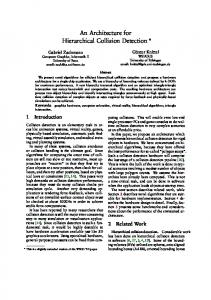
Fig. 1. Semantic Processing Layer Software Architecture Functionality For the parameters of LLSs, Gaussian or mixture of Gaussians models will be utilized. One model will be used for pixel clusters, so that the 640x480 camera pixels translate to 20x15 pixel clusters, each 32x32 pixels in size. Each pixel cluster has models for each type of LLS. The models may need different parameters depending on the number of persons, i.e. it may turn out that people behave differently in groups than they do alone or in pairs. Due to the fact that LLSs can change their type from frame to frame, it would not be a good solution to delete all unlikely LLSs, so they are just marked. After all plausibility checks, a voter decides whether a LLS is handed over to the next layer. In the following, a split and merge algorithm for Gaussian mixture models is introduced, which is used to construct mo-
(2)
• Compute new means (means and variances are calculated in the same fashion; a standard technique is to multiply the old value with the counter, add the new value and divide by (counter + 1); here, this value is additionally weighted with the posterior, ensuring that the current sample is only incorporated into that component where it fits best) μA,s = (1 – Ps(Ar)) · μA,s + Ps(Ar) · (T’ · μA,s + Ar) / (T’ + 1)(3) • Compute new variances σA,s = (1 – Ps(Ar)) · σA,s + Ps(Ar) · (T’ · σA,s + |μA,s - Ar|) / (T’ + 1) (4) • Compute new priors P(s) = (T’ · P(s) + Ps(Ar)) / (T’ + 1)
(5)
• Keep the learning rate and adaptability If T’ ≥ T, T’ = T
(6)
• After some initial iterations (~100), start checking if it is necessary to split components into two new ones with half width: If σA,s > σthreshold, then create two new
4 components (index s and S) from the old (broad) component (index s) μA,S = μA,s + σA,s / 2; μA,s = μA,s - σA,s / 2 σA,S = σA,s / 2; σA,s = σA,s / 2 P(S) = P(s) = P(s) / 2
(7)
• If necessary, merge components (s’ and s’’): If (|μA,s’ μA,s’’| < μthreshold and |σA,s’ - σA,s’’| < σthreshold2) then merge component s’’ into s’ and delete component s’’. Here σthreshold2 < σthreshold, because it is a threshold for a difference, while the latter is a threshold for an absolute value. μA,s’ = (μA,s’ · P(s’) + μA,s’’ · P(s’’)) / (P(s’) + P(s’’)) σA,s’ = (σA,s’ + σA,s’’) P(s’) = P(s’) + P(s’’)
(8)
• If any component’s prior decreased too much so that P(s’) < Pthreshold, then delete the component and adjust the other priors P(s): P(s) = P(s) / ∑ P(s) without P(s’)
(9)
• Repeat with all new values Fig. 2 shows the result of applying the algorithm to data from a real video. The duration of the video is 207.3 seconds consisting of 2074 frames (10 frames per second). In total, 924 different objects moved in the frames with different durations of appearance, ranging from 0.1 seconds to some minutes. degrees
y-axis
x-axis
y-axis
x-axis
Fig. 2: Means and standard deviations of Gaussian mixture models of the direction of moving objects in the camera view. x-axis and y-axis are 16x16 pixel macroblocks of the camera view In the figure we can see three main directions for each pixel cluster. Most of the angles are grouped around the following directions: between 0 to 100°, around 200° and between 250° to 350°. The σ value for each section is smaller than 20° and only at the top left and top right location, there are larger σ values. They occurred because in these locations objects rarely appear and the few angles gathered are not sufficient for constructing a reliable result. Therefore, the σ values remain too large because no split and merge was applied. Such angle
values with large σ need to be omitted during evaluation. The on-line updates of statistical models require only some operations per data point, so this layer consumes virtually no computation time. C. Tracking Description This layer uses particle filter techniques to track the preprocessed LLSs. Our objective is to obtain a record of the trajectories of targets over time and to maintain a correct, unique identification of each target. Traditionally, multiple objects (in the area of particle filters, “objects” (or “targets”) are tracked, rather than “symbols” (or LLSs); therefore, this term is used here) are tracked by multiple single-object-tracking filters. While using independent filters is computationally tractable, the result is prone to frequent failures. Each particle filter samples in a small space and the resulting “joint” filter’s complexity is linear in the number of targets n. However, in cases where targets interact, as in many of our scenarios, single particle filters are susceptible to failures exactly when interactions occur. In a typical failure mode, several trackers will start tracking the single target with the highest likelihood score. On the other hand, tracking multiple objects in one single model increases the sample space by one dimension, which makes it computationally too costly. Hence, a solution with improved multiple single-objects trackers was adopted [22]. Functionality A particle filter specifically designed for tracking interacting objects [22] is used to track the pre-processed objects. The approach for addressing tracker failures resulting from interactions is to introduce a motion model based on Markov random fields (MRFs) [23]. Tracking multiple identical targets becomes challenging when the targets pass close to one another or merge as persons do in a crowd. An approach that relies on the use of a motion model that is able to adequately describe target behavior throughout an interaction event was developed [22]. This approach has a motion model that reflects the additional complexity of the target behavior. The reason for using this approach lies in the fact that the number of LLSs in the observation model can change from sensor observation to sensor observation. E.g., if several persons are walking along a corridor, the visual feature extraction algorithms might detect individual persons in one frame and a group of persons in the consecutive one. In case of unlucky conditions, the detection can change often within short periods of time for the same physical object. The following description is a short summary of the method presented in [22]. The multiple target tracking problem can be expressed as a Bayesian filter. We recursively update the posterior distribution
P( X t | Z t ) over the joint state of all n targets
{ X it | i ∈ 1..n} given all observations Z t = Z1..Z t up to
5 and including time t , according to:
= kP( Z t | X t ) ∫
objects (all possible “lines” between objects):
P( X t | Z t )
P( X t | X t −1 ) P( X t −1 | Z t −1 ) ,
X t −1
(10)
k being a constant for normalization. The likelihood
P ( Z t | X t ) expresses the measurement model, i.e. the
probability we observed the measurement
Z t given the state
X t at time t , which is a model for the modality-related feature
extraction
algorithms.
The
motion
model
P ( X t | X t −1 ) predicts the state X t at time t given the previ-
ous state
X t −1 . In the following, we will assume that the
likelihood
P( Z t | X t ) can be expressed as
P( Z t | X t ) = ∏ P( Z it | X it )
(11)
i =1
i.e. that the targets are conditionally independent, which may not be completely true in case of people, who belong (and move) together, but will hold most of the time between all persons in the crowd. If we assume the targets as being independent, or noninteracting, they can be tracked with single-target particle filters. In other words, the motion model is factored in a product of motion models for individual targets n
P( X t | X t −1 ) = ∏ P( X it | X i ,t −1 ) .
(12)
i =1
t
P( X it | Z ) over
each target’s state X it . In other words, the probability that the current observations are made, because the observed objects behave in a particular way. One view on particle filters is to see them as importance filters for this posterior (using the predicted density state
π it on the
X it as the proposal distribution). Therefore, we assume
the posterior of the previous time being approximated by a set of weighted particles,
{
P( X it | Z t −1 ) ≈ X i(,rt−)1 , π i(,rt−) 1
}
N
r =1
.
(13)
Then, for the current time step, we draw N samples
X it(s )
from a proposal distribution
X it( s ) ~ q ( X it ) = ∑ π i(,rt−) 1 P( X it | X i(,rt−)1 )
(14)
r
which is a mixture of motion models
P( X it | X i(,rt−)1 ) . Finally,
we weight each sample by its likelihood. The resulting set
{ X it( s ) , π it( s ) = P( Z it | X it( s ) )}sN=1 is a weighted approximation for the posterior over the target’s state
X it at time t .
The MRF-based approach for the motion model uses pairwise MRFs, where the
ψ ( X it , X jt )
i
i , j∈E
Each two objects share a particular potential. This term can be incorporated into the Bayesian filter easily, but now we approximate the joint state of all targets, which would result in the necessity of drawing an incredible high number of particles to be able to find a good approximation. Applying the Monte Carlo approximation to the original Bayesian posterior, we get
P( X t | Z t ) ≈ kP( Z t | X t )∑ π t(−r1) P( X t | X t(−r1) ) r
and incorporating the MRF motion model, we obtain
,
(16)
P( X t | Z t ) ≈ kP( Z t | X t ) ∏ψ ( X it , X jt )∑ π t(−r1) ∏ P( X it | X i(,rt−)1 ) (17)
n
The task is to approximate the posterior
P( X t | X t −1 ) ∝ ∏ P( X it | X i (t −1) ) ∏ψ ( X it , X jt ) . (15)
are pair-wise interaction
potentials along edges and E is the space of edges between
r
i , j∈E
i
Fortunately, we see that the interaction potential is independent on earlier states, so it can be treated as additional factor. Unfortunately, approximating this term approximates the joint position of all targets, which is not our desire. Therefore, we apply MCMC (Markov Chain Monte Carlo) sampling, so that the stationary distribution of the chain is exactly the target distribution, and we change only the state of one target at a time by sampling directly from the motion model of that target 1 1 Q( X / | X ) = Q( X / | X , i) = P( X /' | X ( r ) ) δ ( X / = X ) (18) t
t
N
t
t
N
∑ r
it
i ,t −1
∏ j ≠i
jt
i
The acceptance ratio of this sampling method is
P ( Z t | X it/ ) ∏ψ ( X it/ , X /jt ) i , j∈E a S = min1, . P ( Z t | X it ) ∏ψ ( X it , X jt ) i , j∈E
(19)
This method minimizes the computational effort in comparison to joint particle filters for tracking of multiple objects and also minimizes the fault detection rate compared to a set of single-object-tracking particle filters. The effectiveness of this method can be seen in Fig. 3. The great advantages of the tracker lie in the omission of spurious, only very short appearing visual errors and the much better consistency, which is necessary for constructing a model of trajectories of the tracked objects. Both, vision alone and tracker are compared to manually created ground truth, i.e. manually created trajectories. The real number of targets is shown in the bottom sub figure as black line. The tracker is very expensive in computation – our i.MX hardware is able to process around 30 frames per second solely with tracking, which is only slightly dependent on the number of targets, so for a reasonable frame rate the tracker will consume about 20-30% of resources. D. Sensor fusion Description This layer gets as input the stable uni-modal LLSs. Its task is to fuse audio and video symbols. One possibility is to use fac-
6
Number of targets
Number of targets
Number of targets
Meters
Probability
Probability
Number of targets
Frames
Fig. 3: Result of the tracking layer. Shown are zone errors (if a tracker target is outside a 3m radius circle in world coordinates around an original person), distance error (accumulated distance between original persons and closest targets), and consistency error (if a target is not associated with the same original person over time) tor analysis [24], [25], [26] to determine the correlation between audio and video LLSs. The output of this layer is a symbolic representation of the real world in form of a collection of multi-modal LLSs [27]. Functionality Fusion of audio and video data is a task that can be done by correlating the provided data streams. Based on the time correlation of LLSs, the following features can be taken into account for this purpose: loudness, direction of arrivals, and power spectrum of audio LLSs, size in pixels, and position of the video LLSs. In tests with real data audio symbols rarely occurred, so the computational effort for this layer can be neglected. E. Parameter Inference Description The parameter inference layer is responsible for setting up a local semantic description of the events sensed by each node from the set of the LLSs pre-processed by layers 1 and 2. Moreover, the layer automatically establishes neighborhood connections between data representatives. A vector quantization approach is used for learning the data representation, based on the Growing Neural Gas (GNG) algorithm [28]. In particular, we refer to the works of [29] and [30] that use the GNG method for learning high frequency paths in visual surveillance scenarios. Functionality Getting a multi-modal LLS from the sensor fusion layer, the task of this layer is to infer the parameters of the underlying
probabilistic model (Mixture of Gaussians [31]). Unsupervised learning is used to generate a spatial or, depending on requirements, spatio-temporal model of the events. We apply the GNG algorithm as a data-driven vector quantization approach that iteratively generates a codebook of prototypes to represent the data distribution, following the criterion of minimizing the overall network quantization error. The data representation in terms of prototypes provides full coverage of the data. In other terms, even isolated small clusters of data are included in the data representation. Moreover, the number of prototypes is arbitrary, while in other methods, e.g. the K-means clustering, the number of clusters is a parameter to be defined beforehand. The HLSs are generated using the information provided by the prototypes. Each prototype is defined by a position in an N-dimensional feature space and additionally by its neighborhood relations. The standard deviation of the Gaussian distribution associated with each HLS is calculated by taking, for each dimension, the maximum distance of the data points associated to each prototype. The association is done using the Euclidean distance: each representative “wins” all the samples for which it is the nearest representative. Learning Algorithm As already described, instances coming from the low-level sensor-data processing layer are already pre-processed in order to eliminate spurious events. Moreover, objects are tracked for improving object identification over time. In this layer, we further pre-process the data by checking the available tracks from layer 2 for outliers. Moreover, tracks are smoothed to reduce noise effects and improve the computation of the
7 direction of motion for each data point. The statistical data description is learned using a GNGbased approach [28]. The result of the GNG is a codebook C of reference vectors w ∈ C that represent the nodes of the learned network of prototypes and a symmetric adjacency matrix B = bij defining the edges between nodes. The edges are given by a set of links bij ∈{0,1} between the reference vectors wi, wj, i.e. the edges are binary quantities defining the status of each pair of node either as connected or not connected. The algorithm works basically in two steps (see details in [32], [33]): 1) adapting the status of the network and 2) incrementing the number of network nodes. In the network adaptation phase, training samples are randomly selected and the position of the reference vectors in the feature space is adapted in order to decrease the local quantization error. Further, in the second phase, a new reference vector is added to the network at regular time intervals. The position of the new vector is chosen such as to achieve the largest decrease of the network quantization error, i.e. the new vector is located half-way between the reference vector with the highest local error and the one of its neighbors with the highest error.
Fig. 4: Front view of the corridor from the CAVIAR dataset. HLSs in 2D are represented by the ellipses. In blue, a representation of the graph can be seen, including prototype centers and edges.
Fig. 5: Side view of the corridor from the CAVIAR dataset. Superimposed are the HLSs and the corresponding graph of prototypes. Results HLSs are generated using the ground-truth data of the
CAVIAR project, from the PETS 2004 workshop 2. The dataset includes 49 sequences, corresponding to two different camera views, for a total of about 100 trajectories. Persons walk in a corridor with entrances to several shops. The available ground-truth provides for each frame the bounding boxes and IDs of the persons. The reference point used for the trajectories of the training dataset is the head-top. In Figure 4 and Figure 5, two-dimensional HLSs are super-imposed on the two camera views. The original trajectories, in particular in the first camera view (Figure 4) cover a wide range of directions. Moreover, objects in the far distance have low resolution. In this scenario, it is difficult to identify unusual trajectories only on the basis of measured positions and directions as they already have a very broad distribution. Therefore, HLSs of higher dimensionality are required in order to identify unusual events, including additional features such as e.g. velocity, direction of motion, etc. This layer requires the major portion of resources, together with inter-node communication, which affects the weights of HLSs. F. Trajectories Description Trajectories in a node will be derived through the use of a learned transition matrix consisting of transitions between HLSs. Each HLS therefore keeps a list of all local trajectories to which it belongs. At time t, when an observation is associated with that symbol, it will likely not be possible to select the most suitable trajectory for that observation. But considering the sequence of associations of HLSs with that observation, the most probable local trajectory can finally be identified [34], [35]. Additionally, all the neighboring nodes, to which the node has correlations, also activate suitable trajectories, so that the global trajectory also can finally be unambiguously identified. Functionality In addition to the local transition matrix, each node learns the global possible trajectories. Then, a simple switch from one local or global path to another or missing any trajectory causes an alarm for the respective observation. G. Inter-Node Communication Description Inter-node communication is based on the Loopy-Belief Propagation (LBP) algorithm [36], [37]. It serves primarily for detecting neighborhood nodes through correlated symbol activations of HLSs in both neighbors. This knowledge is used both for improving local views through feedback from neighbors and to establish the global view in terms of trajectories. Functionality This is described in [32].
2 http://www-prima.inrialpes.fr/PETS04/pets04.html and http://homepages.inf.ed.ac.uk/rbf/CAVIAR/
8 H. Alarm Generator Description This layer detects predefined alarms and unusual behavior. The major difference between predefined alarms and unusual behavior is that the first can be associated with a predefined, human-readable text, like ”scream noise“ or ”person dropped luggage,“ while the second can detect any situation – not only pre-defined ones – deviating from normal as ”unusual.“ Functionality 1: (Predefined) scenario recognition This method takes the outcome of layer 2 as input. It uses a rule-base [38] to combine these preprocessed LLSs in a hierarchical way to create symbols with higher abstract semantic meaning out of symbols with lower semantic level. While predefined alarms like “screaming person” merely rely on information available from LLSs of the audio modality, alarms like “unattended luggage” require a symbolic processing of different information sources as described in [5]. The definition of predefined alarm scenarios was created based on the expert information of security personnel at Krakow-Balice airport. In close cooperation questionnaires were evaluated and prioritized, and refined in an iterative process, resulting in a concise set of possible alarm scenarios. Since these scenarios are predefined (and not learned during operation) they require explicit modeling by means of specifying patterns over LLSs’ parameters (also in the time domain); thus they allow more precise alarm reporting, e.g. “running person” or “unattended luggage”. Typical considered parameters are location, size, direction (angle), velocity, duration of stay, or loudness (of sound). Functionality 2: Unusual behavior recognition Any observation which cannot be associated with any learned HLS or exhibiting un-normal properties, e.g. unusual duration of association with a certain HLS or trajectory, indicates a deviation from normality and is reported to the next layer [4], [33]. I. User Notification Filter Description This layer builds the interface of the high-level sensor processing. It delivers alarms to the user interface and can be asked about the status of a node or several nodes. It filters identical alarms, e.g. when the same lurking person is reported several times from the predefined scenario recognition; or, if a reported unusual behavior can be matched with a predefined alarm, only the latter will be delivered. Additionally, the user can apply filtering rules to omit or prolong alarms via a GUI. Functionality A basic filtering mechanism for avoiding sending the same alarm several times or sending a per-defined alarm and an unusual behavior for the same thing is applied. An additional rule-base with user preferences is also considered (cf. [39]). IV. TEMPORAL ASPECTS A. Learning Phases Before the system can go operational, it has to learn the normal behavior in the sensed area. This depends essentially on
the variability of the observed events: as soon as changes of the set of learned HLSs due to new observations falls below a certain threshold for a given time, the learning phase is considered as completed. In order to avoid a too early termination in cases where early events are similar by chance, a minimum of observations is required; and to limit the learning phase, a maximum duration for the learning phase can be selected by the customer. Although tests are still ongoing, learning duration between hours and up to few days appear feasible. B. User Notification The duration between detection of a potential threat and its reporting to the customer depends mainly on the type of event and assumed confirmation time, because the propagation of events from the sensors to layer 7 and propagation an alarm from there to the user are below a second. For instance, if an unusual observation shall be reported at least three-times from the low-level layer before considered as real in layer 2, this will take less than 0.5 seconds with the currently possible reporting rate of 8-10 times a second from layer 0. And if an unattended luggage shall be reported if it is observed for at least 10 seconds, it should of course not be reported earlier in order to avoid false alarms. V. DEPLOYMENT The SENSE system has been tested at the international airport MPL Krakow-Balice, Poland. The network connecting the nodes and the GUI PC was closed, and the GUI PC did not have another network connection. However, since the GUI could potentially connect to the nodes also via intranet or internet, special security considerations need to be taken in this case as detailed e.g. in [40]. Fig. 6 shows a mounted SENSE node in 5m height. In sum, 17 nodes have been installed including assembly and cabling.
Fig. 6: Mounted node at airport MPL Krakow-Balice. As detailed in Section III.E, the local view of normal behavior in the observed environment is established in two steps, based on the Growing Neural Gas (GNG) algorithm, representing unsupervised learning. First, the GNG algorithm is used as a data-driven vector quantization approach that iteratively generates a codebook of prototypes to represent the distribution of (the positions of) the video LLSs, following the criterion of minimizing the overall network error (representing the trajectories from the previous step). In a second step, a predefined number of HLSs (high-level symbols), e.g. 50, is generated such that the maximum
9 quantization error with respect to the prototypes is minimized, HLSs are represented by Gaussian distributions; their centers are defined by the vectors computed by the GNG algorithm, and their axes are defined by the standard deviation, which can be seen as the width of the symbols in the multi-dimensional space. Hence, HLSs are usually visualized as ellipsoids. In addition, probability transitions are derived from the edges between the prototypes, which again represent the probability of transition of the LLSs from the area of influence of one symbol to the area of influence of another one. Figure 8 shows the resulting HLS network for the LLSs’ trajectories shown in Figure 7.
hierarchical framework. An example for low level tracking, when tracking a single person in the scene, can be seen in Fig. 9. In this context, the velocity vector is accurately computed and can be the basis of a further “running person” event detection. Scenes consisting of a person and a group of persons yield good results (more than 90% of tracking consistency) as can be seen in Figure 9: the object #11807 keeps the same identifier before and after merging into a group of persons. Tracking consistency is insofar important, as it is the base for computing velocity and angle of movement of persons. If a target is lost, observation can only be restarted for those persons after the tracker created a new target (which takes 0,5s - 1,5s, dependent on the scene).
Fig. 7: Example for LLSs’ trajectories after pre-processing and tracking.
Fig. 8: HLSs derived from the observations shown in Figure 7, using position and direction as features. VI. EXPERIMENTAL EVALUATION According to the defined Application Context, which determined, classified and selected doable application requirements on the base of airport security, expectations and goals of the project, the experimental tests were specified and tested. All percentages are given in TAR 3. A. Lab results The tests have been conducted in two phases, laboratory tests and tests at the installation site, the airport in Krakow. The attachments of the cameras for all lab tests have been conducted in similar heights and angles as later in the airport. The laboratory tests have been very successful with a rate of true positives of 100% for all relevant tests (including detection of left luggage, running person, screaming persons, network changes, and others) throughout all layers in the 3 The TAR (true acceptance rate) consisting of CCO (correctly classified object) and ICO (incorrectly classified objects including false positives and false negatives) as: TAR= CCO/(CCO+ICO) = was 100%.
Fig. 9: Example of successfully tracking B. Airport tests The real-world test results (Table 1) were executed at Krakow-Balice airport on a dedicated test day where special security and preparation measures were taken in order to maintain airport operation. Unfortunately the test day yielded significantly worse results that the tests in lab condition, mainly due to changing weather conditions causing permanent changes in lighting conditions. This caused the video unit to relearn the background frequently, which resulted in times with zero detection rate. However, in case of stable background, the results at the airport reached about 70 – 80%,
10 proving the functionality of the chosen high level approach. Table 1 refers to the test set defined in cooperation with the security personnel at Krakow-Balice airport, testing time is the period of actual recording, the TAR gives the overall true acceptance rate (including changing lighting conditions). The number of samples refers to the test sequences that were executed, that is, luggage has been dropped 14 times, steps were recorded twice (had to be cancelled due to implementation issues) and 18 screams were issued. Here it has to be recalled that the goal of the system is not to automatically detect all threats in the airport environment, but to assist the security staff in pointing their attention to a certain area of interest. The parameters have been chosen to avoid false alarms in order to prevent from annoying the staff, resulting also in a lowered detection rate. Still, the system is bale to point out the location of threats, as long as the background model of the video unit is stable. More advanced background modeling algorithms are already available today, but require more processing power. Hence, this aspect of the system has to be improved when considering product development. The security staff can also request the video stream that led to the generation of any alarm and verify the decision process of the system. But the final decision about disposing staff is left to the humans. Threat/Event - Must Have Functionality Unattended (dropped) luggage Sound of steps Human Scream
Testing Time May 31, 2010 22:22 – 23:37 May 31, 2010 22:53 – 23:02 June 1, 2010 21:42 – 22:43
TAR
Samples
57%
14
0%
2
33%
18
Table 1: Real-world Predefined Alarm Recognition on test day at Krakow-Balice airport VII. CONCLUSION AND OUTLOOK This paper presents a hierarchical processing architecture for smart sensor networks. The innovative aspect lies in the step-by-step processing, through which from the low-level symbols delivered by the sensor layer, information rising through the layers becomes more and more meaningful to a human person in charge. Expected results are described for the deployment in an airport environment. First tests conducted in the airport environment show that the algorithms for tracking and local and global learning work on the target hardware. All layers of the hierarchical processing framework have been described in order to understand the idea behind the architecture. Additionally, the algorithms for pre-processing, tracking of multiple objects, and parameter inference are described in more detail. REFERENCES
[3]
[4] [5] [6] [7] [8]
[9] [10] [11] [12]
[13] [14] [15]
[16] [17] [18] [19] [20] [21] [22] [23] [24] [25]
(all websites visited Jan. 2012) [1] [2]
www.sense-ist.org (SENSE project website) G. Zucker (ne Pratl), and L. Frangu: “Smart Nodes for Semantic Analysis of Visual and Aural Data”, Proceedings of the IEEE INDIN, p. 1001-1006, 2007.
[26]
D. Bruckner, J. Kasbi, R. Velik, and W. Herzner: “High-level Hierarchical Semantic Processing Framework for Smart Sensor Networks”, Proceedings of the 1st Int. Conf. on Human System Interaction HSI’08, Krakow, Poland, 2008. B. Sallans, D. Bruckner, and G. Russ: “Statistical Detection of Alarm Conditions in Building Automation Systems”. In: Proceedings of 2006 IEEE INDIN, p. 6, 2006. G. Zucker (né Pratl): “Processing and Symbolization of Ambient Sensor Data”, Dissertation thesis, Vienna University of Technology, 2006. D. Bruckner: “Probabilistic Models in Building Automation: Recognizing Scenarios with Statistical Methods”, Dissertation thesis, Vienna University of Technology, 2007. R. Velik: “A Bionic Model for Human-like Machine Perception”, Dissertation thesis, Vienna University of Technology, 2009. A. W. Colombo, R. Schoop, and R. Neubert: “An agent-based intelligent control platform for industrial holonic manufacturing systems”, IEEE Transactions on Industrial Electronics, Volume: 52, Issue: 1, p. 322-337, 2006. L. Tianjian, Y. Fujimoto: “Control System With High-Speed and RealTime Communication Links”, IEEE Transactions on Industrial Electronics, Volume: 55, Issue: 4, p. 1548-1557, 2008. S. Theiss, V. Vasyutynskyy, K. Kabitzsch, “Software Agents in Industry: A Customized Framework in Theory and Praxis ”, IEEE Trans. on Industrial Informatics, vol. 56, no. 2, pp. 147 - 156, 2009. M. Metzger, G. Polakow, "A Survey on Applications of Agent Technology in Industrial Process Control ," IEEE Trans. on Industrial Informatics, vol. 7, no. 4, pp. 570-581, Nov 2011. J. Rosell-Ortega, G. Andreu-García, A. Rodas-Jordà, V. AtienzaVanacloig, J. Valiente-González “Feature sets for people, and luggage recognition in airport surveillance under real-time constraints”, International Joint Conference on Computer Vision and Computer Graphics Theory and Applications, Funchal, Madeira – Portugal, 2008. www.Bluetechnix.at A. Malinowski, Hao Yu, "Comparison of Embedded System Design for Industrial Applications," IEEE Trans. on Industrial Informatics, vol. 7, no. 2, pp. , May 2011. D. Tsahalis, G. Nokas, K. Tsokas, and D. Photeinos: “The Use of Decision Tree Classifiers for the Detection of Sound Objects Using Microphone Array Filtered Data”, Proceedings of the 3rd International Conference from Scientific Computing to Computational Engineering, Athens, Greece, 2008. Goldstein, E. B.:“Sensation and Perception“, Cengage Learning, 2009 G. Benet, J. Simo, G. Andreu-García, J. Rosell-Ortega, J. Sanchez, Embedded low-level video processing for surveillance purposes, 3rd IEEE HSI, 2010. Tsahalis D., Nokas G., Tsokas K., Photeinos D., “The Use of Decision Tree Classifiers for the Detection of Sound Objects Using Microphone Array Filtered Data – Part II Applications,” 3rd IC-SCCE, 2008. Schmidt, R.O, "Multiple Emitter Location and Signal Parameter Estimation," IEEE Trans. Antennas Propagation, Vol. AP-34 (March 1986), pp.276-280. G.Q. Yin and D. Bruckner: “Gaussian Mixture Models and Split-Merge Algorithm for Parameter Analysis of Tracked Video Objects”, Proceedings of the 35th IEEE IECON’09. 16. G.Q. Yin, D. Bruckner, and G. Zucker: “Statistical Modeling of Video Object’s Behavior for Improved Object Tracking in Visual Surveillance”, Proceedings of the 9th IEEE AFRICON’09. Z. Khan, T. Balch, and F. Dellaert: “An MCMC-based Particle Filter for Tracking Multiple Interacting Targets”, IEEE Transactions on Pattern Analysis and Machine Intelligence, 2006. R. Kindermann, and J. L. Snell: “Markov Random Fields and Their Applications”, AMS Books Online, ISBN: 0-8218-3381-2, www.ams.org/online_bks/conm1. N. Ueda, R. Nakano, Z. Ghahramani, and G. E. Hinton: “SMEM Algorithm for Mixture Models”, Neural Computation, vol 12, no 9, 2000. Z. Ghahramani, and M. J. Beal: “Variational Inference for Bayesian Mixtures of Factor Analysers”, Advances in Neural Information Processing Systems. vol. 12, MIT Press, 2000. Z. Ghahramani, and G. E. Hinton: “The EM Algorithm for Mixture of Factor Analyzers”, Technical Report CRG-TR-96-1, Department of Computer Science, University of Toronto, 1996.
11 [27] P. Lombardi: “A study on data fusion techniques for visual modules”, Technical. report, University of Pavia, 2002. [28] B. Fritzke, “A Growing Neural Gas Network Leans Topologies”, Advances Neural Information Proc. Systems, Vol. 7, pp. 652-632, 1995. [29] R. P. Pflugfelder, “Visual traffic surveillance using real-time tracking", TR PRIP, Vienna University of Technology, 2005. [30] D. Bauer, N. Brändle, S. Seer, R. Pflugfelder, “Finding Highly Frequented Paths in Video Sequences”, In 18th Int. Conf. on Pattern Recognition (ICPR 2006), Hongkong, China, 2006. [31] C. M. Bishop: “Neural Networks for Pattern Recognition”, New York NY.: Oxford University Press Inc., 1995. [32] C. Picus, L. Cambrini, W. Herzner: ”Boltzmann Machine Learning Approach for Distributed Sensor Networks Using Loopy Belief Propagation Inference“, in Proc. of the 7th Int. Conf. on Machine Learning and Applications ICMLA'08, San Diego, California/USA, 2008. [33] Picus C., Cambrini L., Bruckner D., Zucker G., Herzner W., “A Distributed Approach to Global Semantic Learning over a Large Sensor Network”, Proc. 3rd Intl. Conf. “from Scientific Computing to Computational Engineering” (3rd IC-SCCE), 9 – 12 July 2008. [34] J. Mitterbauer, D. Bruckner, and R. Velik: “Behavior Recognition and Prediction With Hidden Markov Models for Surveillance Systems”, Proceedings of the 8th IFAC FET 2009, p. 204-211. [35] D. Bruckner and R. Velik: “Behavior Learning in Dwelling Environments with Hidden Markov Models”, IEEE Transactions on Industrial Electronics, vol 57, nr 11, p. 3653-3660, DOI: 10.1109/TIE.2010.2045992, 2010 [36] C. Crick and A. Pfeffer: “Loopy belief propagation as a basis for communication in sensor networks”, In Proceedings of Uncertainty in Artificial Intelligence (UAI), 2003. [37] J. S. Yedidia, W. T. Freeman, and Y. Weiss: “Understanding Belief Propagation and Its Generalizations”, IJCAI 2001. [38] W. Burgstaller: “Interpretation of Situations in Buildings”, Dissertation thesis, Vienna University of Technology, 2007. [39] P. Wide: “The electronic head: a virtual quality instrument”, IEEE Transactions on Industrial Electronics, Volume: 48, Issue: 4, p. 766769, 2001. [40] M. Cheminod, A. Pironti, R. Sisto, "Formal Vulnerability Analysis of a Security System for Remote Fieldbus Access," IEEE Trans. on Industrial Informatics, vol. 7, no. 1, pp. , Feb 2011. Dietmar Bruckner (SM'10) holds an MSc in Electrical Engineering and Information Technology since 2004 and a PhD in Technical Sciences since 2007, both from the Vienna University of Technology, Vienna, Austria. His research interests include ambient assisted living, intelligent environments, intelligent automation systems, and in general models for more intelligent decision units. He is with the Vienna University of Technology since 2004, first as project assistant, since May 2009 as University Assistant. He manages the cognitive automation research group since 2007. Dr. Bruckner is IEEE and IES member, holds the positions of IES TC BACM Chair and IEEE Section Austria Chapter Coordinator, and is a member of the Austrian Electrotechnical Association (OVE). He is Associated Editor for Transactions on Industrial Informatics (TII). Cristina Picus studied physics at the University of Cagliari (Italy) and received 2004 her Ph.D. degree in theoretical Physics at the University of Heidelberg (Germany). She is a scientist of the Austrian Institute of Technology, working in the research area of intelligent video systems. From 2004-2006 she worked as researcher for Advanced Computer Vision GmbH (ACV), focusing on the field of automatic recognition and tracking of articulated objects, such as hands, for computer vision applications in real life scenarios. Her background as physicist includes the field of statistical analysis of complex many-particle systems and stochastic simulation using Markov
models. Currently, she is interested in the development of real-time image processing and machine learning algorithms for applications of visual surveillance, e.g. human tracking, multi-camera surveillance. Rosemarie
Velik
studied Electrical Engineering and Information Technologies at the Vienna University of Technology, Austria and obtained a M.Sc. in Automation (’06) and a Ph.D. in Technical Sciences (’08) from the same university. She is a senior researcher with the CTR, Austria. Before this, she held a position as assistant professor at the Vienna University of Technology, Institute of Computer Technology (’06-’09) and positions as senior researcher and project manager at Fatronik, Department of Biorobotics & Neuroengineering, Spain (’09-’10) and Tecnalia Research & Innovation, Department of Rehabilitation Technologies, Spain (’11-’12). Her current main research fields are brain-like artificial intelligence, biomedical engineering, and intelligent sensor technologies. Dr. Velik was honored with the Promotion Sub Auspiciis Praesidentis Rei Publicae due to her first-rate performances during her whole scholastic career. Wolfgang Herzner (M’01) studied Informatics at the Vienna University of Technology, Austria, and received the degree of Diplom-Ingenieur (M.Sc) 1978 and a Ph.D. in Technical Sciences in 1983 there. From 1976 until 1984, he worked at the Institute of information Processing of the Austrian Academy of Sciences, in the area of computer graphics standardization. Since 1984, he is with AIT Austrian Institute of Technology, formerly Austrian Research Center Seibersdorf and Austrian Research Centers. There, he initially led several research and development projects in the area of computer graphics and multimedia; from 1997 to 2002, he was co-developer of a video surveillance and security system. Based on this experience, his research focus turned toward safe software engineering and testing/verification techniques for safety-relevant, software-intensive systems. In that context, he participated and participates in several European projects, e.g. SENSE and MOGENTES (which he both coordinated), DECOS, R3-COP or MBAT. As senior engineer, he today coordinates the research field “Assessment and Testing of Autonomous and Safety-Critical Systems” of the AIT’s department Safety and Security . Dr. Herzner is member of ACM and the Austrian Computer Society (OCG), and was reviewer of IEEE Software and IEEE Software Engineering. Gerhard Zucker (né Gerhard Pratl) (SM’10) is a senior researcher at Austrian Institute of Technology (AIT) since February 2010 in the field of sustainable building technology. His research area includes building automation and controls for optimization of energy efficiency and he works on methods to recognize and evaluate behavior of persons for optimizing building usage and maximizing comfort. He finished his diploma in 1998 at Vienna University of Technology and his Dr. techn. (PhD), viva-voce exam with excellence at TU Vienna in April 2006. In the following he worked on different projects in the field of building automation and artificial intelligence before he did the technical project management of various projects in basic research as well as projects in cooperation with different companies. Gerhard Zucker has a significant publication record, he is editor of two books and numerous scientific publications. He is associate editor of the special issue “Building Automation, Control and Management” in the journal “IEEE Transactions on Industrial Electronics” and lead guest editor of the special issue “Networked Embedded Systems for Energy Management and Buildings“ in the “EURASIP Journal on Embedded Systems”. He was session chair and track chair in various conferences, the latest being track chair at the IEEE “Conference on Industrial Informatics” (INDIN 2010) and special session chair at the “IEEE Human System Interaction 2010 (HSI 2010)”.