The proposed optical security system is based on the JTC configuration as shown in Fig. 1. The JTC input plane con- tains two phase functions h1 and h2 ...
Security optical systems based on a joint transform correlator with significant output images David Abookasis Ortal Arazi Joseph Rosen, MEMBER SPIE Ben-Gurion University Electrical and Computer Engineering Department P.O. Box 653 Beer-Sheva 84105 Israel Bahram Javidi, FELLOW SPIE University of Connecticut Electrical and Computer Engineering Department U-157, 260 Glenbrook Road Storrs Mansfield, Connecticut 06269-2157
Abstract. An improved optical security system based on correlation between two phase-only computer generated masks is proposed. The two phase masks are placed together at the input plane of a joint transform correlator. A priori known output image is obtained in the system output only if one mask is the right key for the other mask. In addition to a simple verification, our security system is capable of identifying the type of an input mask according to the corresponding output image that it generates. The two phase masks are designed using an iterative optimization algorithm with constraints in the input and output domains. Computer simulations are presented with the resultant images formed by the two phase-only elements. © 2001 Society of Photo-Optical Instrumentation Engineers. [DOI: 10.1117/1.1388208]
Subject terms: optical correlators; joint transform correlator; Fourier optics. Paper 200370 received Sep. 18, 2000; revised manuscript received Mar. 28, 2001; accepted for publication Mar. 29, 2001.
1
Introduction 1–5
Recently, several optical processing systems for security have been suggested. Some of these systems evaluate the matching between two phase masks by optical correlation. One optical mask is used as the system’s lock, placed inside the optical correlator. The other optical mask is used as the system’s key, and it is presented to the system by the user in the verification stage. These security systems determine authenticity of the input by comparing the output correlation peak with a predefined threshold value. We propose an optical security system that is based on the existing optical correlators and provides some additional benefits. In our method, the single output correlation peak is replaced by a predefined code, or image, known only to the system designer. Therefore, if and only if this code or image appear on the output plane, as a result of the correlation between the two functions, the true input is verified. The proposed security system also correlates two phase masks, as suggested before,1,2,4,5 but the output is different. In general, phase masks are relatively harder to be counterfeited, since no intensity detector or camera can read the phase mask transparency directly. One needs a relatively complex phase-contrast system to read these types of phase masks. One mask is applied as the key with which the user is verified by the system. The other mask is used as the lock, which is fixed in the system. The predefined image is constructed at the output correlation plane only if the true key appears in the input. Otherwise, a meaningless light distribution is obtained. Forgery in our system becomes more difficult in comparison to other systems. This is because the function of the lock mask here is neither the complex conjugate of the key mask’s1,2,4 function, nor the complex conjugate of its Fourier transform.1,3 To counterfeit the key mask one needs to know both the values of the lock mask 1584 Opt. Eng. 40(8) 1584–1589 (August 2001)
and the complex values of the output image. The proposed system can verify more than one kind of a true input, and can identify the type of input. The same system with the same reference function can yield many images for different input masks. To appreciate this last benefit, let us compare the existing and the proposed systems with real examples. For instance, in a secured plant, the existing verification systems1,2,4 can allow or block someone entering in. Our system can do the same, but in addition it can identify the authorized person that asks to enter, and distinguish them from other authorized persons. That is because each person gets a different key function, which yields a different code in the system’s output when the key mask is introduced in the input. Another example might be an input phase mask attached onto a money bill, as suggested in Ref. 1. One can design a verification system of money bills that reads the phase mask by the correlator, and yields a series of codes, each of which contains secretive information about every bill. Unless the intruder knows the expected image and can project this image on the output camera, it will be impossible to illegally bypass the correlator. One can argue that because the correlator’s output is an image, this image should be automatically recognized. If a second optical correlator is added to recognize the output of the first one, the output result of the second correlator is a correlation peak, which can be counterfeited in this stage. To contrast this claim, we note that optical pattern recognition is not always the best option for recognizing the output of the first correlator. If the output image is binary with a simple shape, or it is some code like a barcode, and it appears alone on the output plane at more or less the same location, it can be easily recognized by a digital computer with an appropriate software. Breaking into a digital pattern recognition system seems harder than just illuminating the camera with an in-
0091-3286/2001/$15.00
© 2001 Society of Photo-Optical Instrumentation Engineers
Abookasis et al.: Security optical systems . . .
where 丢 denotes the correlation operator, and a and b are the distances between h 1 and h 2 in the x and y directions, respectively. The useful terms are either the third or the fourth term, since both represent the cross-correlation between the two input functions. We choose one of them, say the third term, as the output of the security system. This output distribution is complex valued and is expressed by c 共 x,y 兲 ⫽h 1 丢 h 2 ⫽A 共 x,y 兲 exp关 i 共 x,y 兲兴 ,
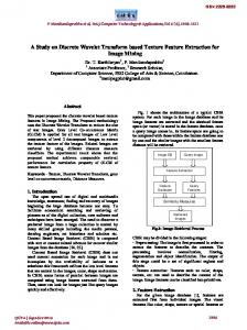
Fig. 1 The JTC correlator used for optical security verification.
tense light spot. Moreover, in many cases the decision whether a presented identification card is legitimate or not is performed by a human rather than by an automatic machine. In these cases a clear image in the output of the verification system is preferred over a peak of light. The human brain recognizes known images more easily than comparing an intensity of light to some threshold value. In conclusion we claim that, although the verification process in two stages adds complexity, it also adds two new benefits: 1. improvement of the security level, and 2. more information about the verified user or product. We implement our security scheme with the joint transform correlator 共JTC兲.1,4,5 The main advantage of this scheme over the VanderLugt correlator3,6,7 is the less restrictive alignment requirements. The lateral distance between the two masks can be changed within a reasonable tolerance without changing the shape of the output image. Only the image location on the output plane is changed according to the relative distance between the two phase masks. On the other hand, in the VanderLugt correlator a slight mutual shift between the filter and the light distribution coming from the input considerably modifies the correlation results.8 The values of the phase mask used as the system’s lock are determined once by a random numbers generator. The system design problem is to find the second phase mask 共the key兲 such that a correlation between the two masks yields an intensity pattern as close as possible to a predefined image. This design problem is actually equivalent to a nonlinear optimization problem. We choose to compute the mask’s values by a modified version of the projection onto constraint sets 共POCS兲 algorithm,9 adjusted for the JTC.10 This algorithm is a relatively rapid iterative process, but it usually achieves suboptimal solutions. 2 Synthesis of a Key Mask in the JTC The proposed optical security system is based on the JTC configuration as shown in Fig. 1. The JTC input plane contains two phase functions h 1 and h 2 located apart from each other. The output of the correlator contains three spatially separated diffraction orders as follows,8 o 共 x,y 兲 ⫽h 1 共 x,y 兲 丢 h 1 共 x,y 兲 ⫹h 2 共 x,y 兲 丢 h 2 共 x,y 兲 ⫹h 1 共 x,y 兲 丢 h 2 共 x⫺a,y⫺b 兲 ⫹h 2 共 x,y 兲 丢 h 1 共 x⫹a,y⫹b 兲 ,
共1兲
共2兲
where A(x,y) is the amplitude of the expected output image, and (x,y) denotes the phase function of c(x,y). The computation of the phase-only mask h 1 , which produces the desired output image from the cross-correlation intensity distribution with the other random phase-only mask h 2 , is performed by the modified POCS algorithm. The POCS is an iterative process, which in the present case transfers a function, by the JTC operator, from one domain to another. In every domain, the resulting function is projected onto a constraint set by two projection operators denoted by P 1 and P 2 ; both are defined in the following. The convergence of the process is achieved when the function satisfies all the constraints in every domain simultaneously. The POCS process is implemented on a JTC-like configuration and depicted in Fig. 2. This iterative algorithm starts with an initial random phase function denoted by h 1,1 , and another random phase function h 2 , which remains fixed thereafter. The overall input function of the JTC in the first iteration is u 1 共 , 兲 ⫽h 1,1共 ⫹a/2, ⫹b/2兲 ⫹h 2 共 ⫺a/2, ⫺b/2兲 .
共3兲
The support areas of the phase functions h 1 ( , ) and h 2 ( , ) are 关¯ 1 ⫻ ¯ 1 兴 and 关¯ 2 ⫻ ¯ 2 兴 , respectively. The function u 1 ( , ) is Fourier transformed into the spatial frequency plane, where the phase factor is extracted 共in the box PE兲 and memorized until the iterated function is transformed back to the 共, 兲 domain. This procedure is needed to keep as much information as possible on the projection of u j ( , ) in the j’th iteration, such that the distance between P 2 关 u j ( , ) 兴 and u j⫹1 ( , ) is kept minimal. From the frequency plane, according to an ordinary JTC, the square magnitude of the spatial spectrum is inversely Fourier transformed to yield the output function o j (x,y). The projected function P 1 关 o j (x,y) 兴 is Fourier transformed back to O j ( f x , f y ) in the frequency domain. The next necessary operation is to calculate the square root of the spectrum. O j ( f x , f y ) is a real function because P 1 关 o j (x,y) 兴 is symmetric. However, the projection P 1 may cause O j ( f x , f y ) to have negative values. To avoid calculating the square root of negative values, the absolute value of the minimum of O j ( f x , f y ) is identified 共in the box MF兲 and added to the function O j ( f x , f y ). The addition of uniform bias effects only the central value of the correlation plane and thus does not contradict the constraints in this plane, enforcing only on the two first diffraction orders, as seen in Eq. 共4兲. After calculating the square root of a real positive spectrum, we multiply this result by the memorized phase factor of the spectrum in the forward step, as denoted in Fig. 2 by exp兵i arg关U j(f x ,f y)兴其. This last product is inversely Fourier Optical Engineering, Vol. 40 No. 8, August 2001 1585
Abookasis et al.: Security optical systems . . .
Fig. 2 Block diagram of the POCS process used to compute the phase-only mask h 1 ( , ); FT is Fourier transform, PE is the phase extraction, MF is the minimum finder, and P i is the i th projection.
transformed back to the 共, 兲 plane. Finally u j ( , ) is projected by P 2 and the next iteration starts. As mentioned, at every iteration, in each of the two domains, 共x, y兲 and 共, 兲, the resulting functions are projected onto the constraint sets. In the 共x, y兲 domain the constraint set reflects the expectations to get the predefined image represented by the positive function A(x,y). Therefore, in the output plane, the projection P 1 on the constraint set is as follows, P 1 关 o j 共 x,y 兲兴
⫽
冦
A 共 x⫺a,y⫺b 兲 exp关 i j 共 x,y 兲兴 兩 x⫺a 兩 ⭐W x /2 and 兩 y⫺b 兩 ⭐W y /2
A 共 ⫺x⫺a,⫺y⫺b 兲 exp关 i j 共 x,y 兲兴 兩 x⫹a 兩 ⭐W x /2 and 兩 y⫹b 兩 ⭐W y /2
共4兲
o j 共 x,y 兲 Otherwise,
where W x and W y are the width and the height of the desired output image centered around (x,y)⫽(a,b) and (⫺a,⫺b). This constraint set guarantees that the spectrum O j ( f x , f y ) remains a real function. j (x,y) is the phase function of o j (x,y), and it obeys the rule j (x,y)⫽⫺ j (⫺x,⫺y). In the input domain 共, 兲 the constraint set manifests the properties of the input functions as phaseonly functions in a predefined area and zero elsewhere. Therefore, the projection P 2 is 1586 Optical Engineering, Vol. 40 No. 8, August 2001
P 2 关 u j 共 , 兲兴
⫽
冦
exp关 i j 共 , 兲兴 兩 ⫺a/2兩 ⭐¯ 1 /2 and 兩 ⫺b/2兩 ⭐ ¯ 1 /2
h 2 共 ⫹a/2, ⫹b/2兲 兩 ⫹a/2兩 ⭐¯ 2 /2 and 兩 ⫹b/2兩 ⭐ ¯ 2 /2
共5兲
0 Otherwise,
where exp关i j(,)兴 denotes the phase of u j ( , ). The algorithm continues to circulate between the two domains until the error between the actual and the desired output functions is not meaningfully reduced anymore. Note that h 2 ( , ) is chosen in the initial step of the iterations, and becomes a part of the correlator and is never changed during the iteration process. Moreover h 2 ( , ) is not in any way related to h 1 ( , ) or the output image, and is not in any kind of the system’s memory. Therefore h 2 ( , ) does not limit the quantity of key-mask output-image pairs that can be processed by the same key function h 2 ( , ). The present security system can be viewed as a generalization of the Fresnel computer-generated hologram. On this analogy, h 2 ( , ) plays the rule of a generalized medium between h 1 ( , ) and the reconstructed output image A(x,y), in a similar fashion as the quadratic phase factor represents the free-space medium in the Fresnel hologram reconstruction.11 The medium function can be used as a lock to expose an image but it does not contain any infor-
Abookasis et al.: Security optical systems . . .
mation on the image, and therefore its size does not limit the image capacity that can be utilized by the system. The convergence of the algorithm to the desired image in the n’th iteration is evaluated by the average meansquare error 共MSE兲 between the intensity of the correlation function before and after the projection, as follows e j⫽
1 M
冕冕
兩兩 P 1 关 o j 共 x,y 兲兴 兩 2 ⫺ 兩 o j 共 x,y 兲 兩 2 兩 2 dxdy,
共6兲
where M is twice the area of the output images. Unlike the correspondent algorithm in the VanderLugt correlator,7 the convergence of the process is not guaranteed. From our experience, the MSE here decreases to some saturation level and fluctuates slightly around this level. Apparently, the obtained output images resulting from the algorithm of Ref. 7 are less noisy than the results here. However, the comparison is not done in an equal condition and therefore it is hard to determine which algorithm leads to a lower MSE. We chose an arbitrary number of iterations, much larger than it takes to converge to the saturation level. During the iterations we keep the key function h 1 that gives the minimum MSE in the memory, and this function is used as the final solution of the process. 3 Simulation Results We performed a computer simulation, demonstrating our proposed system discussed before. In the simulation, the algorithm was tested with two different binary output images. The first one is composed from the letters EIFLT, as shown in Fig. 3 in a symmetrical position on the JTC’s output plane. The JTC input and output planes have 256 ⫻256 pixels each. In the input domain, each of the two correlated functions covered only 70⫻230 pixels of phaseonly values. All the rest of the matrix outside these two windows was padded with zeros, as shown in Fig. 4. The lock phase mask was positioned in the lower part of the plane, and was not being changed during the process. The algorithm was terminated after 100 iterations and the resultant correlation functions can be seen in Fig. 5. The plot of the MSE, defined in Eq. 共6兲, for this experiment is shown in Fig. 6. The three orders of the correlation plane and the letters images in the two first diffraction orders can be clearly seen in Fig. 5, demonstrating that our algorithm is effective to accomplish its goal. Note that a low dynamic range of the joint power spectrum is not a problem here, since both the masks h 1 and h 2 are phase masks that yield an almost uniform joint power spectrum. In the second experiment the output image was a picture of a barcode, shown in Fig. 7. The reconstructed picture is shown in Fig. 8. The error function plot is shown in Fig. 9. The behavior of the MSE along the iterations and the quality of the final result are similar to that of the first experiment. 4 Conclusions We have developed a method of designing an optical security system based on computer generated optical diffractive elements. According to our method, one can design two phase-only transparencies for a JTC correlator to receive a chosen code or image. The resulting masks can be used for
Fig. 3 The expected output image used in the first computer simulation.
Fig. 4 Phase functions of the mask h 1 (upper) and h 2 (lower) on the JTC input plane.
Fig. 5 Resultant image of the JTC output plane for the letters of Fig. 3. Optical Engineering, Vol. 40 No. 8, August 2001 1587
Abookasis et al.: Security optical systems . . .
Fig. 6 MSE versus the number of iterations of the POCS system for the experiment with the letters.
Fig. 9 MSE versus the number of iterations of the POCS system for the experiment with the barcode.
security systems such that the desired code is received on the output plane only when the specific phase masks are placed on the JTC input plane. Since the computing of the holograms starts from completely random functions, they cannot be reproduced, even if the output image is known. With the same phase mask of the system’s lock, the correlator can produce infinite output images by introducing different input key masks. Therefore, in addition to simple verification, the system can provide information on the identity of the authorized person. The implementation of the security system by a JTC avoids alignment difficulties between the various optical components.
Fig. 7 The expected output image used in the second computer simulation.
Fig. 8 The reconstructed image of the barcode shown in Fig. 7. 1588 Optical Engineering, Vol. 40 No. 8, August 2001
References
1. B. Javidi and J. L. Horner, ‘‘Optical pattern recognition for validation and security verification,’’ Opt. Eng. 33, 1752–1756 共1994兲. 2. B. Javidi, G. S. Zhang, and J. Li, ‘‘Experimental demonstration of the random phase encoding technique for image encryption and security verification,’’ Opt. Eng. 35, 2506 –2512 共1996兲. 3. H.-G. Yang and E.-S. Kim, ‘‘Practical image encryption scheme by real-valued data,’’ Opt. Eng. 35, 2473–2478 共1996兲. 4. B. Javidi and A. Sergent, ‘‘Fully phase encoded key and biometrics for security verification,’’ Opt. Eng. 36, 935–942 共1997兲. 5. T. Nomura and B. Javidi, ‘‘Optical encryption using joint transform correlator architectures,’’ Opt. Eng. 39, 2031–2035 共2000兲. 6. R. K. Wang, I. A. Watson, and C. Chatwin, ‘‘Random phase encoding for optical security,’’ Opt. Eng. 35, 2464 –2469 共1996兲. 7. Y. Li, K. Kreske, and J. Rosen, ‘‘Security and encryption optical systems based on a correlator with significant output images,’’ Appl. Opt. 39, 5295–5301 共2000兲. 8. J. W. Goodman, Introduction to Fourier Optics, 2nd ed., Chap. 8, p. 242, McGraw-Hill, New York 共1996兲. 9. Image Recovery Theory and Application, 1st ed., H. Stark, Ed., Academic Press, New York 共1987兲. 10. J. Rosen and J. Shamir, ‘‘Application of the projection-ontoconstraint-sets algorithm for optical pattern recognition,’’ Opt. Lett. 16, 752–754 共1991兲. 11. O. Bryngdahl and F. Wyrowski, ‘‘Digital holography/computergenerated holograms,’’ in Progress In Optics, E. Wolf, Ed., Vol. 28, pp. 1– 86 共1990兲.
Abookasis et al.: Security optical systems . . . David Abookasis received BSc and MSc degrees in electrical and computer engineering from Ben-Gurion University of the Negev, Beer-Sheva, Israel, in 1997 and 2001, respectively. His research thesis is optical imaging through a thin layer of blood. He is currently pursuing a PhD in electrical and computer engineering from Ben-Gurion University. His research interests include image reconstruction, holography, optical tomography, and optical correlators. Ortel Arazi: Biography and photograph not available. Joseph Rosen received his DSc in electrical engineering from the Technion-Israel Institute of Technology in 1992. He is currently an associate professor in the Department of Electrical and Computer Engineering, Ben-Gurion University of the Negev. He has coauthored more than 50 scientific papers in refereed journals. His research interests include image processing, diffractive optics, interferometry, pattern recognition, holography, optical tomography, and statistical optics.
Bahram Javidi obtained his MS and PhD from The Pennsylvania State University in 1982 and 1986, respectively, and his BS from George Washington University in 1980, all in electrical engineering. His research interests are optics for information and imaging systems. He is a fellow of the Institute of Electrical and Electronics Engineers (IEEE), fellow of the Optical Society of America (OSA), and fellow of the International Society for Optical Engineering (SPIE). In 1990, he was named a Presidential Young Investigator by the National Science Foundation. His publications include two books, nine book chapters, 110 journal articles, and 112 conference proceedings, including 40 invited papers. He is the topical editor of the IEEE/SPIE Press Series on Imaging Science and Engineering, topical editor of Marcel-Dekker Publishers, Chairman of the IEEE LEOS Technical Committee on Electro-optics Sensors and Systems, and Chairman of the Optics in Information Systems Working Group of SPIE.
Optical Engineering, Vol. 40 No. 8, August 2001 1589