deterministic optimization algorithm (SDA). The ap- proach is compared ... the coupled equations can be written as: dR dz. (z) = iËÏ(z)R(z) + iκ(z)S(z). (2). dS dz.
Semi-Deterministic vs. Genetic Algorithms for Global Optimization of Multichannel Optical Filters Benjamin Ivorra, Bijan Mohammadi, Patrick Redont Mathematics and Modelling Institute, University Montpellier II, 34095 Montpellier, France
Laurent Dumas Jacques-Louis Lions Laboratory University of Paris VI, 75252 Paris, France
Olivier Durand Alcatel CRC, 91460 Marcoussis, France Abstract: A new global optimization algorithm is presented and applied to the design of high-channel-count multichannel filters based on sampled Fiber Bragg Gratings. We focus on the realization of particular designs corresponding to multichannel filters that consist of 16 and 38 totally reflective identical channels spaced 100 GHz. The results are compared with those obtained by a hybrid genetic algorithm and by the classical sinc method. Keywords: global optimization; semi-deterministic algorithms; genetic algorithms; optical fiber devices; multiplexing.
1
INTRODUCTION
interleaved amplitude-only sampling patterns for yielding interleaved groups of channels (Loh et al., 1999). However, The use of new optical fiber devices in the telecommu- a predictable number of peaks inside an overall square ennication sector has known an important development in velope is still difficult to reach in this case. the last few years. Among them, Fiber Bragg Gratings A lot of work was then performed for optimizing the (FBG) based devices represent an attractive alternative sampling pattern either in amplitude (Ibsen et al., 1998) for applications such as multichannel filtering, multichanand/or in phase (Buryak et al., 2003; Rothenberg et al., nel optical add/drop multiplexing, multichannel dispersion 2002). In the case of amplitude optimization, the index compensation and multiwavelength laser sources. Focusmodulation amplitude of the sampling was optimized foling on this last domain, the FBG functionality is to ensure lowing a Fourier analogy (Ibsen et al., 1998). In the case the choice of desired wavelengths by forming a step-tunable of phase-only optimization, only the relative phase of the laser (Chow et al., 1996; Wei et al., 2000). It may be incorchannels to be generated are continuously modified and porated either in all-fiber structures such as erbium-doped the amplitude modulation of the sampling is minimized. fiber ring lasers or hybridized with an external Fabry-Perot Such an approach was first demonstrated with semiconcavity (Helmers et al., 2002). One way to perform their reductor laser Bragg reflectors (Ishii et al., 1993) and it was alization is to use sampled FBGs. Such filters are made of recently applied to FBG (Rothenberg et al., 2002). Ala spatial comb distribution of identical sampling gratings. though this method can generate as many as 51-channel Pioneer works on this topic have reported results obfilters, phase-variation is still difficult to inscribe, requirtained with amplitude-only sampling through the writing ing a customized lithographically prepared phase mask or of periodic transmitting and opaque regions inside the fiber a high precision inscription technique. core (Eggleton et al., 1994). The main drawback in this case is the sinc envelope of the spectral response due to the There is therefore an important demand for optimizasquare index envelope of every transmitting region. The tion methods for the design of sampling patterns giving uniformity of the response is then limited to only a few a desired reflectivity spectrum (Rothenberg et al., 2002). nanometers. In order to overcome this non-uniformity, it In addition, the method requires performing global optiwas proposed to insulate the opaque regions with sets of mization as it is observed that functionals have multiple
1
E+
While the modes are orthogonal in an ideal waveguide and therefore do not exchange energy, the presence of a dielectric perturbation causes the modes to be coupled. Introducing the detuning parameter:
Λ core z−axis
ζ=β−
2πnef f π π = − Λ λ Λ
and the new unknowns: φ(z) 2 ) φ(z) + 2 )
E−
R(z) = A(z) exp(iζz −
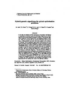
S(z) = B(z) exp(−iζz Figure 1: Fiber Bragg grating diagram: Dark stripes correspond to core zone where the refractive index is modulated. the coupled equations can be written as: The fiber reflects a certain wavelength band, E-, and allows dR (z) = iˆ σ (z)R(z) + iκ(z)S(z) other one, E+, to pass. Λ represents the grating period. dz
dS (z) = −iˆ σ (z)S(z) − iκ(z)R(z) dz
minima (Skaar and Risvik, 1998). In this paper we introduce a new global semideterministic optimization algorithm (SDA). The approach is compared to a well known genetic algorithm (Dumas et al., 2004; Goldberg, 1989) and applied to the design of FBG structures. We show that superior results can be found with this method from both industrial realizability and computational complexity point of view. Section 2 presents the Fiber Bragg Grating devices and their mathematical modelling. Section 3 describes our optimization method and recalls the basis of genetic algorithms. Finally, in section 4 we discuss different designs of high-channel-count multichannel filters.
2
(2) (3)
When δnef f is small compared to nef f , the two coupling coefficients can be approximated by: σ ˆ (z) = ζ + σ(z) −
1 dφ δnef f (z) 1 dφ (z) = ζ + β − (z) 2 dz nef f 2 dz
and
ν σ(z) 2 σ is called the ’dc’ (demi coupling) and κ the ’ac’ (associated coupling) coefficient. This system known as the two modes coupling model is completed by the following boundary conditions: κ(z) =
Fiber Bragg Gratings (FBG)
L R(− ) = 1 2
Fiber Bragg Gratings are based on the perturbation of the effective refractive index of an optical guide in order to reflect a predetermined wavelength band and to let other bands pass (see Figure 1). To write a FBG in an optical fiber, we expose it to UV Laser radiation. This radiation will modify the refractive index of the optical guide core in a periodic or an aperiodic way (Erdogan, 1997). In order to derive a mathematical model of a FBG, we assume there exist only two counterpropagating guided modes in the FBG of respective amplitudes A(z) and B(z) for any wavelength λ in the transmission band. We denote by nef f the unperturbed refractive effective index and by β the corresponding propagation constant. The perturbation by UV exposure, denoted by nef f , of the refractive effective index along the fiber axis z is given by: ¸ · 2π z + φ(z) ) (1) δnef f (z) = δnef f (z)(1 + ν cos Λ
(4)
(the forward-going wave is incident from −∞) and L S( ) = 0 2
(5)
(there is no backward-going wave for z ≥ L2 ). The main characteristics of a FBG is then expressed through its complex spectral response in the transmission band: λ ∈ [λmin , λmax ] 7→ ρ(λ) =
S(− L2 ) R(− L2 )
(6)
from which we deduce its power reflection function: λ ∈ [λmin , λmax ] 7→ r(λ) = |ρ(λ)|2 2.1
[− L2 , L2 ],
where z ∈ L is the fiber length, Λ is the nominal grating period, δnef f (z) is the slowly varying index amplitude change over the grating (also called apodization), ν is the fringe visibility and φ(z) is the slowly varying index phase change (also called chirp).
(7)
Uniform FBG
If the grating is uniform along z, then the apodization δnef f and the chirp φ are constant functions, as well as κ and σ. Thus, equations (2-3) reduce to a system of firstorder coupled ordinary differential equations with constant coefficients.
2
The number of secondary side loops of this function, (2 ∗ (Nl − 1)), being proportional to the total number of targeted channels, a 16-peak filter was demonstrated with a profile exhibiting 14 secondary side loops between the −κ sinh(ωL) √ ρ(λ) = (8) main lobes. To physically express the negative values of the Sinc function, discrete π-phase shifts (or equivalently σ ˆ sinh(ωL) + i κ2 − σ ˆ 2 cosh(ωL) sign changes in the profile) were inserted between each side and loop. However, this type of profile suffers several drawbacks. A great number of π-phase shifts must be inserted sinh2 (ωL) as the number of channels increases, which requires master(9) r(λ) = 2 cosh2 (ωL) − σκˆ 2 ing the writing process. Moreover, as the number of channels increases, the duty cycle (i.e. the ratio between the √ where ω = κ2 − σ ˆ2. central lobe and the rest of the grating) decreases proportionally to N1 . Most of the energy deposited onto the fiber finally concerns the writing of the central lobe so that the 2.2 Non-uniform FBG strength of reflectivity of the grating strongly decreases. In Non-uniform apodization and chirped refractive index are this way, a 16-channel count FBG with a reflectivity of 0.95 suitable in applications. These permit a better reduction requires a maximum index variation up to 6.10−4 . Such of undesirable sidelobes appearing in uniform FBG power values are impossible to realize in practice. In addition, reflection functions. For instance, a non uniform apodiza- using highly photosensitive fibers gives rise to a nonlinear tion of a FBG can eventually produce a power reflection regime during the UV-writing. All this makes it important function very close to the often desired ”top-hat” shape. to find profiles easier to implement by optimization. In this case, the complex spectral response and the power reflection function are approximated by decomposing the FBG in a set of N uniform elementary fibers of L length N . Expressions (8-9) are then used on each of 3 Optimization methods these fibers to find the overall coefficients of the complete FBG. This leads to the so-called simplified transfer matrix We propose to use two types of minimization methods. A typical genetic algorithm (Dumas et al., 2004; Goldberg, method (Erdogan, 1997). 1989) and a new global minimization method based on a recursive search for the attraction basins of any local 2.3 Non uniform sampled FBG optimization algorithm. A sampled FBG is a superstructure made of a comb distribution of a sampling pattern. This is an efficient and 3.1 Genetic algorithm simple technique to construct a grating that exhibits periodic maxima in its spectrum. Using the coupled mode Consider the minimization of a real functional J(x), x ∈ theory (Erdogan, 1997), it can be shown that a spatial Ωad , x is the optimization parameter and belongs to an comb distribution leads to a comb of peaks with identical admissible space Ωad . Genetic algorithms approximate the response and with a wavelength separation ∆λ varying as: global minimum (or maximum) J through a stochastic process based on an analogy with the Darwinian evolution of 2nef f Λ2 species: ∆λ = (10) P • A family (xi )1≤i≤Np of Np possible solutions of the opwith P the period of the sampling patterns distribution. timization problem, called ’individuals’, is first ranThe computation of the reflectivity coefficients of a samdomly created in the search space Ωad in order to pled FBG remains unchanged compared to the one exposed constitute the first generation of the ’population’. in the previous paragraph (Erdogan, 1997). But this calculation is more time-consuming. • Each individual, representing a potential solution of the given problem, is ranked relatively to its associated value through an auxiliary ”fitness” function 2.4 The inverse problem of non uniform sampled (inversely proportional to J in the case of a minimizaFBG tion problem). In this process (selection process), betIn order to obtain a multi-channel filter, Ibsen et al. (Ibsen ter individuals, in terms of the fitness function, have et al., 1998) have shown the possibility to inscribe inside higher chances to be chosen for reproduction. the fiber core a Sinc-shaped apodization function (see Figure 3) with a continuous writing technique: • The next generation is then made from the current generation by creating ’offsprings’ (crossover process) sin( 2NLl πz ) from different pairs of individuals; the offsprings may δnef f (z) = (δnef f )max 2Nl πz (11) in turn eventually ”mute” (mutation process). L More precisely, the complex spectral response and the power reflection function can be approximated by the following expressions (see (Skaar and Risvik, 1998)):
3
With these three basic evolution processes, it is gener- A1 (v1 , N, I, ²): ally observed that the best obtained individual is getting closer after each generation to the optimal solution of the • Input: v1 , N, I, ² problem (Goldberg, 1989; Dumas et al., 2004). In practice, • v2 chosen randomly as final convergence is difficult with GA based algorithms, For i going from 1 to N one should always complete GA iterations by a descent • oi = D(vi , I, ²) method for better accuracy, these approaches are called • oi+1 = D(vi + 1, I, ²) ’hybrid algorithms’. • If J(oi ) = J(oi+1 ) EndFor Engineers like GA’s because these do not require sen• If min{J(ok ), k = 1, ..., i} < Jm + ² EndFor i+1 −vi sitivity computation, perform global and multi-objective • vi+2 = vi+1 − J(oi+1 ) J(ovi+1 )−J(oi ) optimization and are easy to parallelize. Their drawbacks EndFor remain their weak mathematical background, their com• Output: A1 (v1 , N, I, ²) = argmin{J(ok ), k = 1, ..., i} putational complexity and their lack of accuracy. The semi-deterministic algorithm (SDA) presented below aims Above the inputs are v1 ∈ Ω, (N, I) ∈ IN2 and ² ∈ IR. to address these issues. As this line search minimization algorithm might fail, an external level to the algorithm A1 is added in order to have 3.2 Semi-deterministic multi-level optimization a multidimensional search. As previously, we consider v1 = We want to minimize a functional J : Ω → IR (where Ω is w as a new variable in A1 to be found by the minimization a subset of IRn ) subject to the following hypotheses (Mo- of: hammadi and Saiac, 2002): J ∈ C 1 (Ω, IR) and is coercive ˜ h(w) = h(A1 (w, N, I, ²)) (13) (i.e. J(x) → +∞ when |x| → +∞ in Ω). The minimum of J is denoted Jm . In cases where Jm is unknown, we set To perform the minimization of (13), we then consider Jm = 0 and look for the best solution for a given complex- the following two-level algorithm with an output called A2 (w1 , M, N, I, ²): ity and computational effort. The general idea of the Semi Deterministic Algorithm • Input: w1 , M, N, I, ² (SDA) is to improve the efficiency of any particular local • w2 chosen randomly deterministic minimization algorithms (Gradient, Newton, For i going from 1 to M etc...), by making it global. It is based on a recursive • pi = A1 (wi , I, ²) search for the attraction basins of the local algorithm. • pi+1 = A1 (wi + 1, I, ²) For the sake of simplicity, we will only consider here the • If J(pi ) = J(pi+1 ) EndFor following optimal descent algorithm with an output called • If min{J(pk ), k = 1, ..., i} < Jm + ² EndFor D(x0 , I, ²): i+1 −wi • wi+2 = wi+1 − J(pi+1 ) J(pwi+1 )−J(pi ) EndFor • Input: x0 , I, ² • Output: A2 (w1 , M, N, I, ²) = argmin{J(pk ), k = • x1 = x0 1, ..., i} For n going from 1 to I • Determine ρopt = argminρ (J(xn − ρ∇J(xn ))) using Above w1 ∈ Ω, (M, N, I) ∈ IN3 and ² ∈ IR . In order dichotomy n+1 n n to add search directions, the previous construction can be •x = x − ρopt ∇J(x ) easily pursued recursively. • If J(xn+1 ) < Jm + ² EndFor EndFor The choice of the initial condition w1 in this algorithm • Output: D(x0 , I, ²) = xn+1 contains the only non-deterministic feature of the SDA Above the inputs x0 ∈ Ω, ² ∈ IR and I ∈ IN are method. In practice we randomly choose the initial condirespectively the initial condition, the stopping criterion tion w1 ∈ Ω and we consider (N, M, I) = (5, 5, 10). These values give a good compromise between computation comand the iteration number. plexity and result accuracy. Mathematical background for We consider that the minimization problem is solved if this approach and validation on academic test cases are the initial condition x0 lies in the attraction basin of the available (Mohammadi and Saiac, 2002; Debiane et al., global minimum of J. In order to determine such an initial 2004). condition, we consider x0 = v as a new variable in the previous algorithm to be found by the minimization of: 4
h(v) = J(D(v, I, ²)) − Jm
Optimization problem
(12)
The GA and the SDA algorithms above are applied to solve To perform the minimization of (12), we then con- the inverse problem of sampling pattern design of highsider the following algorithm with an output called channel-count multichannel filters. We exhibit designs of
4
100 mm long multichannel filters centered around 15525 nm that consist of 16 and 38 totally reflective identical channels spaced 100 GHz. We discuss their spectral characteristics and compare them to the responses obtained with currently used Sinc-profiles.
0.8
Cost function Reflectivity
4.1
1
We design a sampled FBG knowing its power reflection function (7). We can reformulate this problem considering that each sampled FBG with no chirp can be characterized by its apodization (or equivalently refractive index modulation) z 7→ δnef f (z), we denote by Ωapo the associated search space of all acceptable apodization profiles. The functional is given by: J(x) = kr(x) − rtarget (x)kL2 ([λmin ,λmax ])
0.6
0.4
0.2
(14)
0 1.545
where r(x) is the power reflection function of the sampled FBG with an apodization associated with x ∈ Ωapo and rtarget (x) the nearest perfect power reflection function to r(x) matching the desired requirements.
1.55
1.555
1.56
wavelenght (µm)
Figure 2: Example of ideal reflectivity for a 16-peak filter. 4.2
Parameterization
In order to find a multi-channel filter with the desired spectral response and associated with an index modulation with some ’interesting’ characteristics (smooth enough, slowly varying and symmetric), apodization profiles are generated by spline interpolation through a reduced number of NS points equally distributed along the first half of the sampling pattern and completed by parity. We will choose a value of NS high enough to ensure a large number of peaks in the spectral response but small enough to ensure improvement in the index modulation profile in comparison with the classical Sinc profile. Thus, the corresponding search space of the optimization problem is a hypercube: ΩNS = [−nmax , nmax ]NS where nmax is a design constraint. Here nmax = 5.10 The functional on ΩNS is defined by: Nc X
(r(x)(λi ) − rtarget (x)(λi ))2
Results and discussion
Two different FBG configurations have been considered for optimization with GA and SDA algorithms above. The results have been compared to the empirical technique based on Sinc functions. The grating profile has been optimized on the entire length of a sampling period equal to 1.039 mm, corresponding to an interchannel spacing ∆λ = 0.8 µm (10). The total length of the grating is set to 103.9 mm. The initial core effective refractive index is n0 = 1.45. For the genetic algorithm, we have chosen the following values for the three associated stochastic processes (see section 3.1). The crossover is barycentric in each coordinate with a probability of 0.45. The mutation process is non-uniform with a refinement parameter of 1.1 and probability of 0.15. The selection is a roulette wheel type proportional to the rank of the individual in the population. A one-elitism principle, that consists in keeping the best current individual in the next generation, has also been imposed. The population size has been set to 180 and the maximum generation number to 30. For the semi-deterministic algorithm, we use a threelevel structure with M = N = 5 iterations for the external levels and I = 10 iterations of conjugate gradient as core optimization method (calculations after doubling these numbers give rise to the same solutions). We see that the complexity in terms of calculation and memory requirement is quite low. These parameters are fixed and used in all computations.
(15) −4
JNc (x) =
5
.
(16)
i=1
In the above expression, the power reflection function r(x) of the filter with an apodization associated with x ∈ ΩNS is evaluated on Nc wavelengths equally distributed on the transmission band by using the simplified transfer matrix method (Erdogan, 1997). On the other hand, rtarget (x) denotes the nearest perfect power reflection function to r(x) matching the desired requirements (see Figure 2), namely Npeaks transmitted wavelengths with a transmission rate greater than 0.95 and separated by ∆λ: ½ 5.1 Npeaks= 16, Ns=9, Nc=1200 max(0.95, r(x)(λ)) if λ ∈ Λ rtarget (x)(λ) = (17) 0 elsewhere Figures 3 and 4 show the apodization variation profile and with Λ = {λx , λx +∆λ, . . . , λx +(Npeaks −1)4λ}, λx being the associated power reflection function between 1540 and 1560 µm for three different filters: Sinc, GA and SDA (i.e. the lowest frequency peak and for λ ∈ [λmin , λmax ]. 5
Sinc 6.6 ··· 0.4 5 10−4 14
GA 5.9 5400 0.15 2.1 10−4 6
SDA 3.1 3000 0.03 1.9 10−4 4
6
Refractive index modulation × 10−4
JNc value Evaluation number Out-of-band rejection ∆nmax Phase shifts
Table 1: 16-peak multichannel filter: left to right, results with Sinc, GA and SDA apodization profiles. obtained by these optimization procedures). The Sinc filter has a cost function of 6.59. The GA filter gives 5.83. The total number of functional evaluations is 5400 and the best element was found at generation 21 of GA after 3780 evaluations. The SDA filter gives 3.09. The total number of functional evaluations is about 3000. The best element was found at iteration 169 after 2028 evaluations. This is important as Sinc profiles are considered efficient and realistic for the realization of these filters. Convergence histories are given in Figure 5. The three values of the cost function show that both GA and SDA algorithms have led to better solutions in terms of reflection characteristics than the Sinc profile. This is visible in Figure 3 on the respective interchannel and out-of-band rejection (undesirable side peaks) which is reduced to 0.03 in the SDA profile and to 0.15 in the GA profile, to be compared to 0.4 for the Sinc profile. In addition, optimized profiles are more suitable for industrial realization as the number of necessary phase shifts (when δnef f (z) = 0) is only 6 for the GA profile and 4 for SDA against 14 for the Sinc-profile and the index modulation of profiles is more homogeneously distributed along the pattern and does not exhibit any dominant lobe. A last improvement concerns the maximum amplitude of the profile which has been reduced to ∆nmax = 2.10−4 for both GA and SDA profiles. These results are summarized in Table 1.
2
0
−2 0
0.2
0.4 0.6 0.8 Position along the grating (mm)
1
Refractive index modulation × 10−4
6
4
2
0
−2 0
0.2
0.4
0.6
0.8
1
Position along the grating (mm)
6
Npeaks= 38, Ns=15, Nc=2400
Refractive index modulation × 10−4
5.2
4
4
In this case, the classical sinc-type profile exhibits better spectral characteritics than the SDA and GA optimized profiles as can be observed in Figures 6 and 7 or in the 2 corresponding values of JNc (9.1 for sinc against 10.3 for SDA and 13.9 for GA). Furthermore, the GA optimized profile fails to exhibit all the 38 peaks with a reflection higher than 0.95. However, the sinc profile is difficult to 0 build because of its large amount of phase shifts (36) and its large maximum index amplitude (6 × 10⁻⁴ ). Actually, the SDA algorithm could have found results equivalent to, −2 or better than, the sinc-type profile if a larger value Ns 0 0.2 0.4 0.6 0.8 1 Position along the grating (mm) had been taken (e.g. Ns > 40). However, to avoid the above-mentioned experimental difficulty, we explicitly removed such unsuitable profiles with the choice of a reduced search space. Thus, the obtained FBG is easier to im- Figure 3: 16-peak multichannel filter. From top to bottom: plement as the number of phase shifts is reduced to 14, SINC, GA and SDA optimized filters apodization. the index modulation is more homogeneously distributed and the maximum amplitude of the profile is reduced to
6
11
9
7
5
3 5
10
15
20
25
30
11
9
7
5
3 50
100
150
200
250
Figure 5: 16-peak multichannel filter. GA (Left) and SDA (Right) convergence histories: Best element (solid line) and global convergence (dashed line).
JNc value Evaluation number Peak number ∆nmax Phase shifts
Sinc 9.8 ··· 38 6 10−4 36
GA 13.9 5400 34 3.5 10−4 22
SDA 10.3 4500 38 4.8 10−4 14
Table 2: 38-peak multichannel filter: left to right, results with Sinc, GA and SDA apodization profiles. ∆nmax = 4.8 × 10⁻⁴ (see Table 2). The total number of functional evaluations is now 4500 for SDA and almost unchanged for GA at 5400. With GA, the best element is found at generation 28 after 5040 evaluations (almost at the end) while it is reached at iteration 89 after 1602 evaluations by SDA. This is visible in Figure 8.
Figure 4: 16-peak multichannel filter. From top to bottom: Sinc, GA and SDA optimized filters associated spectra.
6
Conclusion
Two configurations of high channel count filters based on non-chirped apodized fiber Bragg gratings have been
7
6
Reflectivity
Refractive index modulation
0.8
3
0
0.6
0.4
−3 0.2
−6 0
0.2
0.4 0.6 0.8 Position along the grating (mm)
1.54
1
1.55 wavelength (µm)
1.56
1.57
6
Reflectivity
Refractive index modulation × 10−4
0.8 3
0
−3
0
0.6
0.4
0.2
0.2
0.4 0.6 0.8 Position along the grating (mm)
1
1.54
1.55 wavelength (µm)
1.56
1.57
Refractive index modulation × 10−4
6
3
0
3
−6 0
0.2
0.4
0.6
0.8
1
Position along the grating (mm)
Figure 6: 38-peak multichannel filter. From top to bottom: SINC, GA and SDA optimized filters apodization.
Figure 7: 38-peak multichannel filter. From top to bottom: Sinc, GA and SDA optimized filters associated spectra.
8
analyzed by global optimization methods using a semideterministic and a hybrid genetic optimization algorithm. This leads to the creation of four filters with different FBG apodization profiles. The results obtained by the semideterministic algorithm outmatch those by the genetic algorithm and also the sinc method traditionally used in industry. The grating solutions produced by the semideterministic approach are easier to manufacture because they have no step variation, lower maximum index modulation value and also smaller number of π-phase shifts in the sampling pattern. A prototype of this fiber is developed by the Electronic and MicroOptoElectronic Center at Montpellier University. Recently, this approach has been successfully extended to the design of Spectral Code Division Multiple Access (spectral CDMA) filter devices (Ivorra et al., 2004).
25
20
Acknowledgements 15
The authors would like to thank Professor Yves Moreau from the Electronic and MicroOptoElectronic center of the University of Montpellier (CEM2). 10
5
10
15
20
25
30
REFERENCES 25
Buryak, A.V., K.Y. Kolossovski and D.Y. Stepanov (2003), ‘Optimization of refractive index sampling for multichannel fiber bragg gratings’, IEEE Journal Quantum Electron. 39, 91–98.
20
Chow, J., G. Town, B. Eggleton, M. Ibsen, K. Sugden and I. Bennion (1996), ‘Multiwavelength generation in an erbium-doped fiber laser using in-fiber com filters’, IEEE Photonic Technology Letter 8(1), 60–62.
15
10
Debiane, L., B. Ivorra, B. Mohammadi, F. Nicoud, A. Ern, T. Poinsot and H. Pitsch (2004), Temperature and pollution control in flames, in ‘Proceeding of the Summer Program’, Center for Turbulence Research, NASA Figure 8: 38-peak multichannel filter. GA (Top) and AMES/Stanford University, USA, pp. 367–375. SDA (Bottom) convergence histories: Best element (solid line) and global convergence (dashed line). Dumas, L., V. Herbert and F. Muyl (2004), ‘Hybrid method for aerodynamic shape optimization in automotive industry.’, Computers and Fluids 33(5), 849–858. 50
100
150
200
250
Eggleton, B.J., P.A. Krug, L. Polodian and F. Ouellette (1994), ‘Long periodic superstructure bragg gratings in optical fibres’, Electronic Letter 30(19), 1620–1622. Erdogan, T. (1997), ‘Fiber grating spectra’, Journal of LightwaveTechnology 15(8), 1277–1294. Goldberg, D. (1989), Genetic algorithms in search, optimization and machine learning., Addison Wesley.
9
Helmers, H., O. Durand, G.H. Duan, E. Gohin, J. Landreau, J. Jacquet and I. Riant (2002), ‘45 nm tunability in c-band obtained with external cavity laser including novel sampled fibre bragg grating.’, Electronic Letter 38(24), 1535–1536. Ibsen, M., M.K. Durkin, M.J. Cole and R.I. Laming (1998), ‘sinc-sampled fiber bragg gratings for identical multiple wavelength operation’, IEEE Photonic Technology Letter 10(6), 842–844. Ishii, H., Y. Tohmori, Y. Yoshikuni, T. Tamamura and Y. Kondo (1993), ‘Multiple-phase-shift super structure grating dbr lasers for broad wavelength tuning’, IEEE Photonic Technology Letter 5(6), 613–615. Ivorra, B., B. Mohammadi, L. Dumas, Y. Moreau, G. Pille and O. Durand (2004), ‘Apodisation de fibres `a r´eseaux de bragg pour la synth`ese de codes cdma spectral’, Conference COSTO04, IEEE Lasers and Electro-Optics Society French Chapter . Loh, W.H., F.Q. Zhou and J.J. Pan (1999), ‘Novel designs for sampled grating-based multiplexers-demultiplexers’, Optics Letter 34(21), 1457–1459. Mohammadi, B. and J-H. Saiac (2002), Pratique de la simulation num´erique, Dunod. Rothenberg, J.E., H. Li, Y. Li, J. Popelek, Y. Sheng, Y. Wang, R.B. Wilcox and DJ. Zweiback (2002), ‘Fiber bragg gratings and phase-only sampling for high channel counts’, IEEE Photonic Technology Letter 14(9), 1309– 1311. Skaar, J. and K.M. Risvik (1998), ‘A genetic algorithm for the inverse problem in synthesis of fiber gratings.’, Journal of Lightwave Technology 16(10), 1928–1932. Wei, D., T. Li, Y. Zhao and S. Jian (2000), ‘Multiwavelength erbium-doped fiber ring lasers with overlap-written fiber bragg gratings’, Optics Letter 25(16), 1150–1152.
10