Index Termsâ Induction Motor; Direct Torque Control; Direct Torque Neural Control ..... [7] James N. Nash, Direct Torque Control, Induction Motor Vector Control.
International Journal of Scientific & Engineering Research, Volume 7, Issue 6, June-2016 ISSN 2229-5518
220
Sensor less DTC Using Artificial Intelligent Technique as Switching Vector Selector Eng.Mohammed Hamouda Ali, Dr. Salama Abo-Zaid, Prof.Dr. Abd elsamia Kotb Abstract— This paper is based on the detailed study on the characteristic of sensor less direct torque control (DTC) and output vector of the three-phase inverter, a simplified method to choose the output vector for DTC of the three-phase inverter fed induction motor is proposed. And a novel switching vector selector using the ANN (Artificial neural network) is trained under the tutor of the method mentioned above. By the usage of the ANN, when the error of the torque and stator flux is made certain, the output vector can be expediently acquired. The validity of the proposed vector selector is confirmed by the simulative results. The approach in this paper was based on the model reference adaptive control observing the rotor flux, which estimate motor mechanical speed requiring only stator quantities, the stator currents and voltages. Index Terms— Induction Motor; Direct Torque Control; Direct Torque Neural Control; Model Reference Adaptive System Control (MRAS).
—————————— ——————————
1 INTRODUCTION
T
he induction Motors are often termed the “Workhorse of the Industry”. This is because it is one of the most widely used motors in the world. It is used in transportation and industries, and also in household appliances, and laboratories [1]. The robustness, the low cost, the performances and the ease of maintenance make the asynchronous motor advantageous in many industrial applications or general public.
IJSER
More than a decade ago, direct torque control (DTC) was introduced to give a fast and good dynamic torque response and can be considered as an alternative to the field oriented control (FOC) technique [2], [3]. The configuration is much simpler than the FOC system due to the absence of frame transformer. It also does not need pulse width modulator and position encoder, which introduces delays and requires mechanical transducers respectively. It was introduced in 1986 [2].
Direct torque control has a very fast response and simple structure which makes it to be more popular used in industrial world [4]. The key features of DTC compared to standard field oriented control includes [5]: • • • •
No current loops so current not directly regulated. Coordinate transformations not required. No separate voltage pulse width modulator. Stator flux vector and torque estimation required.
2 THE BASIC PRINCIPLES CONTROL [6]
OF
DIRECT TORQUE
In the DTC scheme the electromagnetic torque and stator flux error signals are delivered to two hysteresis controllers as shown in Fig.1. The stator flux controller imposes the time duration of the active voltage vectors, which move the stator flux along the reference trajectory, and the torque controller determinates the time duration of the zero voltage vectors, which keep the motor torque in the defined-by-hysteresis tolerance band.
Fig.1 Block scheme of the direct torque control method The corresponding output variables
,
and the stator
are used to select the appropriate voltflux position sector age vector from a switching table scheme (Takahashi & Noguchi, 1986), which generates pulses to control the power switches in the inverter. At every sampling time the voltage vector selection block chooses the inverter switching state, which reduces the instantaneous flux and torque errors. The stator flux of the induction motor can vary quickly compared to the rotor flux. DTC makes use of this property. The DTC uses two hysteresis controllers namely flux controller and torque controller to this. The control variables flux and torque are expressed in terms of stator variables. So the estimation and control of these variables becomes simple. The output of the controller determines the switch positions of the inverter which in turn accelerate or decelerate the stator flux. Hence the torque is changed at faster rate. At the same time flux controller tries to keep the operating flux around the reference value [7].
IJSER © 2016 http://www.ijser.org
International Journal of Scientific & Engineering Research, Volume 7, Issue 6, June-2016 ISSN 2229-5518
221
In practice the hysteresis controllers are digitally implemented. This means that they function within discrete time . Consequently, the control of whether the torque or the flux is within the tolerance limits, often delays depending on the duration of the sampling period. This results in large ripples in the torque and the current of the motor.
The undesirable ripples in the electromagnetic quantities appear when the control of the values of the torque and the flux takes place at times when their values are near the allowed limits. This means that a voltage vector will be chosen which will continue to modify these quantities in a time , even though these limits have been practically achieved. Accordingly, in the next control which will be carried out after time , these quantities will be quite different from the desirable values. Another reason why the electromagnetic torque of the motor presents undesirable ripples is the position of the in each of the six sectors of its transition. In general, an undesired ripple of the torque is observed when the moves towards the limits of the cyclic sectors and generally during the sectors’ change. Furthermore, the torque ripple does not depend solely on the systems conditions but also on the position of in the sector as well.
Fig.3 Available stator voltage vectors.
4
PRINCIPLES OF SWITCHING TABLE
The main concept for employing a switching table in DTC is that the estimated values of stator flux and electromagnetic torque are compared to reference values, i.e. Fig.5 and through what is called hysteresis controller shown in Fig.4. These two hysteresis controllers are different for torque and flux. Because the flux and torque have to fall into a certain band for switching table DTC, we have two limits, which is considered as the tolerance number of allowing being “how far” from the desired value we can employ this method and still be accurate. In practice, the flux controller provides two cases (a two level controller). In contrast to achieve the desired output torque the hysteretic controller need provide three separate cases. The equations 2 and 3 represent the hysteresis band limits for the flux tables and equations 4 through 6 represent the three levels hysteresis bands of the torque tables [10].
IJSER
3 VECTOR MODEL OF INVERTER OUTPUT VOLTAGE [8]
In a voltage fed three phases, the switching commands of each inverter leg are complementary. So for each leg a logic state Ci (i=a, b, c) can be defined. Ci is 1 if the upper switch is commanded to be closed and 0 if the lower one in commanded to be close.
The output signals , for for for for for
,
are defined as: (2) (3) (4) (5) (6)
Fig.2 Three phase voltage inverter Since three are three independent legs there will be eight different states, so eight different voltages. Applying the vector transformation described as: (1) Where: is the dc voltage. As it can be seen from the above equation, there are six nonzero voltage vectors and two zero voltage vectors which correspond to (C1, C2, C3) = (111)/ (000) as shown by Figure.3. [2] [9].
Fig.4 The hysteresis controllers a) two-level, b) three-level
IJSER © 2016 http://www.ijser.org
International Journal of Scientific & Engineering Research, Volume 7, Issue 6, June-2016 ISSN 2229-5518
222
TABLE I.
2.switching table for Conventional DTC
Sector 1
Flux
2
3
4
5
6
Torque
Fig.5 (a)The hysteresis band controls the stator flux voltage, (b): The torque is controlled by the three level hysteresis bands. Where is the flux tolerance band and is the torque tolerance band. Table 1 represents the switching table logic based on the equations 2 to 6. This results in the six sectors of the hysteretic table below for inverter outputs. TABLE I.
1.The switching table logic Increase
IJSER
5 STATOR FLUX LINKAGE AND TORQUE CONTROL [4] When the proper inverter voltage sequence ( - ) is selected, the stator flux is going to be rotating at the desired synchronous speed within the specified band. As mentioned earlier, the stator flux monotonically follows the stator voltage, when the stator resistance is small enough to be neglected. Thus, changing the stator flux space vector can be accomplished by changing the stator voltage during a desired period of time.
Decrease or
or
The Conventional DTC and its six sectors proposed by I. Takahashi and T. Nogouchi [2].
(7) (8)
Where Δt =
, is the sampling period.
We can obtain the electromagnetic flux using and the electromagnetic torque depends on the sin of the angle between the stator flux and rotor flux, i.e. , as = . Since it is easier to adjust the stator flux through the stator voltage, the variation of the developed electromagnetic torque is done by varying the stator flux vector, the stator flux magnitude and the angle between stator flux and rotor flux because the rotor flux is slowly moving but the stator flux can be changed immediately.
Fig.6 Conventional DTC and its six sectors The switching selection table for stator flux vector lying in the first sector of the d-q plane as shown by figure 6 is given in Table.2 [2], [11].
(9) Where P, is the number of poles Therefore, angle as well as torque can be changed thanks to the appropriate selection of voltage vector.
IJSER © 2016 http://www.ijser.org
International Journal of Scientific & Engineering Research, Volume 7, Issue 6, June-2016 ISSN 2229-5518
223
ing the difference between the input voltage and the voltage drop across the stator resistance as given by equations 15 and 16:
(10) The analysis performed by the optimal switching logic is based on the mathematical spatial vector relationships of stator flux, rotor flux, stator current, and stator voltage. The torque developed by the motor is proportional to the cross product of the stator flux vector and the rotor flux vector . The magnitude of stator flux is normally kept as constant as possible and torque is controlled by varying the angle between the stator flux vector and the rotor flux vector. This method is feasible because the rotor time constant is much larger than the stator time constant. Thus, rotor flux is relatively stable and changes quite slowly, compared to stator flux. When an increase in torque is required, the optimal switching logic selects a stator voltage vector that develops a tangential pull on the stator flux vector , tending to rotate it counterclockwise with respect to the rotor flux vector . The enlarged angle created effectively increases the torque produced. When a decrease in torque is required, the optimal switching logic selects a zero-voltage vector, which allows both stator flux and produced torque to decay naturally. If stator flux decays below its normal lower limit the flux status output will again request an increase in stator flux. If the torque status output is still low, a new stator voltage vector is selected that tends to increase stator flux while simultaneously reducing the angle between the stator and rotor flux vectors.
(15)
(16) The stator flux linkage phasor is given by:
(17)
(18) By comparing the sign of the components stator flux ( ) and the amplitude of stator flux, we can localize the zone where we find the flux. During the switching interval, each voltage vector is constant and equations 15 and 16 is then rewritten as in equation 19:
IJSER
6 STATOR FLUX AND TORQUE ESTIMATOR
Stator voltage components ( , ) on perpendicular ( , ) axis are determined from measured values ( and Isa, b, c). Boolean switching controls (C1, C2, C3,) by, [2] [11]:
(11)
(12) And stator current components (
,
):
(13)
(14) The stator resistance can be assumed constant during a large number of converter switching periods . The voltage vector applied to the induction motor remains also constant during one period . The stator flux is estimated by integrat-
(19)
In equation; stands for the initial stator flux condition. In fact, we have . Electromagnetic torque can be calculated from [11], [12]:
(20)
Where: is number of poles.
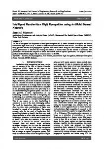
7 ANN BASED DIRECT TORQUE CONTROL
The neurons artificial network is a model of calculation with a conception schematically inspired by the real neurons functioning system. It constitutes an approach which gives more opportunities to approach the problems of perception, memory, learning and analysis under new angles. It is also a very promising alternative to avoid certain limitations of the classic numeric methods. Due to its parallel treatment of the information, it infers emergent properties able to resolve problems qualified in the past as complex [13]. In this paper, a neuronal controller is used to replace switching table, where the inputs are the error of flux torque and the position angle of stator flux, and the output is the impulses allowing the control of the inverter switches [14], [15], [16]. in order to generate this neuronal controller by Matlab / Simulink, we selected three linear feed-forward layers with five neurons in the first layer plus thirteen neurons at the second layer, and six neurons at the output layer, with the activation functions respectively of type ‘logsig’, 'tansig' and 'purelin'. The structure of the direct neuronal torque control of an asynchronous machine is illustrated bellow in figure 7.
IJSER © 2016 http://www.ijser.org
International Journal of Scientific & Engineering Research, Volume 7, Issue 6, June-2016 ISSN 2229-5518
8.1
224
Reference model
The reference rotor flux components obtained from the refeence model are given by: (21)
8.2
Adaptive model
The rotor flux components obtained from the adaptive model are given by: (22)
Fig.7 Direct torque neural networks controller scheme
8 MODEL REFERENCE ADAPTIVE SYSTEM (MRAS) Sensor less drives are becoming more and more important as they can eliminate the speed sensor maintaining accurate response. Monitoring only the stator current and stator voltages, it is possible to estimate the necessary control variables. The observer type used here is a MRAS. The basic scheme of the MRAS configuration is given in figure 8. The scheme consists of two models; reference and adjustable ones and an adaptation mechanism. The block “reference model” represents voltage model which is independent of speed. The block “adjustable model” is the current model which is using speed as a parameter. The block “adaptation mechanism” estimates the unknown parameter using the error between the reference and the adjustable models and updates the adjustable model with the estimated parameter until satisfactory performance is achieved. Since the MRAS is a close-loop system, the accuracy can be increased. However, the models contain pure integrators which cause estimation error due to unknown initial condition and estimation drift due to offset in the measured currents [17], [18].
8.3 Adaptation Mechanism Finally, the adaptation scheme generates the value of the estmated speed to be used in such a way as to minimize the error between the reference and estimated fluxes. In the classical rotor flux MRAS scheme, this is performed by defining a speed tuning signal , to be minimized by a PI controller which geerates the estimated speed which is fed back to the adaptive model. The expressions for the speed tuning signal and the estimated speed can be given as:
IJSER
(23)
(24)
above a symbol in equations 21 to 24 denotes estimated quantities, symbol p stands for , is the rotor time costant and . All the parameters in the motor and the estimator are assumed to be of the same value. Undlined variables are space vectors, and sub-scripts V and I stand for the outputs of the voltage (reference) and current (adjustble) models, respectively. Voltage, current and flux are denoted with u, i and , respectively, and subscripts s and r stand for stator and rotor, respectively. Superscript s in space vector symbols denotes the stationary reference frame.
Fig.8 Conventional MRAS speed observer
IJSER © 2016 http://www.ijser.org
International Journal of Scientific & Engineering Research, Volume 7, Issue 6, June-2016 ISSN 2229-5518
9
225
Simulation Model and Parameters
IJSER Fig.9 Simulink Model of DTC
The parameters of the induction motor are shown in table .3: TABLE I.
3.parameters of the induction motor
Power Stator Resistance Rs Rotor Resistance Rr Stator Inductance Ls Rotor Inductance Lr Mutual Inductance M Phase Voltage V Inertia J Frequency f
3hp 1.115Ω 1.083 Ω 0.209674H 0.21344H 0.2037H 265V 0.02Kgm 60HZ
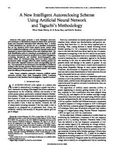
Fig.10 speed estimation against actual speed (ANN DTC).
10 SIMULATION RESULT Conventional DTC MATLAB model was developed for 3hp induction motor at 1e-6 sec sampling time and VSI DC link voltage is 500V. speed estimation against actual speed (DTC).
Fig. 1.
Fig.11 speed estimation against actual speed (DTC). IJSER © 2016 http://www.ijser.org
International Journal of Scientific & Engineering Research, Volume 7, Issue 6, June-2016 ISSN 2229-5518
Fig.12 error on speed estimation (ANN DTC).
226
Fig.16 stator flux magnitude (ANN DTC).
IJSER
Fig.13 error on speed estimation (DTC).
Fig.17stator flux magnitude (DTC).
Fig.14 electromagnetic torque against the load torque (ANN DTC).
Fig.15 electromagnetic torque against the load torque (DTC).
IJSER © 2016 http://www.ijser.org
Fig.18 stator current in phase a, b (ANN DTC).
Fig.19 stator current in phase a, b (DTC).
International Journal of Scientific & Engineering Research, Volume 7, Issue 6, June-2016 ISSN 2229-5518
227
Fig.20 stator current in phase a, b at steady state (ANN DTC). Fig.23 stator flux in d-q stationary frame (DTC). The Induction motor speed controlling model using Conventional DTC and ANN applied DTC has been designed and studied successfully and the results of the thesis work are almost satisfying by using ANN in it as a substitution of the switching table. To compare with Conventional DTC and ANN DTC for Induction motor are simulated. The dynamic responses of speed, flux, torque and stator current for the starting process with 0 Nm load torque then 7 Nm at 0.4sec and input speed reference of 100 rpm applied are shown in Figure from 10 to 23 respectively. Figs.14 and 15 show the response of electric torque of the Conventional ANN DTC, and DTC respectively. It can be seen that the ripple in torque with ANN DTC control is less than 1Nm and with conventional direct torque control the ripple is about 3 Nm at the same operating conditions. Figs.16 and 17 show the response of stator flux magnitude of the Conventional ANN DTC and DTC respectively. By ANN DTC technique shown Fig 16, the stator flux is the fast response in transient state and the ripple in steady state is reduced remarkably compared with conventional DTC, the flux changes through big oscillation and the torque ripple is bigger in Conventional DTC. In Fig 10 and 11, It can be seen that the ripple in speed with ANN DTC is less than 0.06 rpm and with conventional direct torque control the ripple is about 1 rpm at the same operating conditions. Figs 18 and 19 show the stator current response of the ANN DTC and DTC respectively. The steady state current of the ANN DTC has negligible ripple in stator current and a nearly sinusoidal wave form while as with conventional DTC the stator current has considerably very high ripple as shown in Figs 20 and 21.
IJSER
Fig.21 stator current in phase a, b at steady state (DTC).
11 CONCLUSION Fig.22 stator flux in d-q stationary frame (ANN DTC).
In this paper a conventional DTC and ANN DTC of induction IJSER © 2016 http://www.ijser.org
International Journal of Scientific & Engineering Research, Volume 7, Issue 6, June-2016 228 ISSN 2229-5518 motor with estimated speed using the MRAS have been pro[11] Depenbrock, M: Direct self – control (DSC) ofinverter – fed induction maposed. From the above the conventional direct torque control chine, IEEE Trans. Power Electronics, Vol.3, N°.4, Oct 1988, PP.420-829. technique is used for DTC control of Induction motor. In con[12] Toufouti, R. - Benalla, H. - Meziane S: Three- Level Inverter with Direct ventional DTC method some disadvantages such as difficulTorque Control ForInduction Motor, World Conference on Energy for Susties in torque and flux control at very low speed, high current tainable Development: Technology Advances and Environmental Issues, and torque ripple, variable switching frequency behavior, PyramisaHotel Cairo - Egypt, 6 - 9 December 2004. high noise level at low speed and lack of direct current con[13] ‘’Neural Systems for Control’’, ISBN: 0125264305, Elsevier Science & Technology Books, February 1997. trol, an adaptive torque controller must be proposed for high performance applications. So an Artificial Neural Network [14] Luis A. Cabrera, Malik E. Elbuluk, and Donald S. Zinger, ‘’Learning Tech(ANN) control is proposed for conventional DTC scheme. The niques to Train Neural Networks as a State Selector for Inverter-Fed Inducintelligent technique ANN are used for proper voltage vector tion Machines Using Direct Torque Control’’, IEEE-PE, Vol. 12, No. 5, pp 788selection in DTC so that the rotor speed, torque and flux per799}, Sep, 1997, pp 788-799. formances of induction machine is improved. The conven[15] Y.V. Siva Reddy, M. Vijayakumar and T. Brahmananda Reddy, ‘’Direct tional DTC controller compared with ANN and the results Torque Control of Induction Motor Using Sophisticated Lookup Tables are carried out by using MATLAB/Simulink. Based on Neural Networks’’, AIML Journal, Vol.7, Issue 1, June, 2007. The main improvements shown are: [16] R. Toufouti, S. Meziane, H. Benalla, ‘‘Direct Torque Control for Induction Motor Using Intelligent Techniques’’ Journal of Theoretical and Applied In• Reduction of torque and current ripples in transient formation Technology, pp 35-44, JATIT,2007. and steady state response. [17] Lotfi Baghli ‘‘Contribution à La Commande de la Machine Asynchrone, • No flux droppings caused by sector changes circular Utilisation De la logique floue, Des réseaux De Neurone et des Algorithmes trajectory. Génétiques’’ Thèse de Doctorat en génie électrique l’université Henri Poinca• Operating without speed sensor. ré, Nancy le 14/01/1999. • Good dynamic behavior and steady state responses [18] C.Schauder, “Adaptive Speed Identification for Vector Control of Induction of speed and flux even at low and high speed. Motors Without Rotational Transducers,” IEEE Trans. On Industry Applications, vol. 28, no. 5, pp. 1054-1061, 1992.
REFERENCES [1]
[2]
[3] [4]
[5]
[6]
[7] [8]
[9]
IJSER
DevrajJee (109EE0039), Nikhar Patel (109EE0087),” V/f Control of Induction Motor Drive”, Department of Electrical Engineering National Institute of Technology Rourkela-769008 (ODISHA) May-2013. I. Takahashi, T. Noguchi, “A New Quick Response and High-Efficiency Control Strategy of an Induction Motor”, IEEE Trans. Ind. Appl., vol IA-22, No 5 Sept/Oct 1986, PP.820-827. P. Tiitinen, “The Next Generation Motor Control Method, DTC Direct Torque Control”, Proc. OfInt. Conf on Power Electronics, Drives andEnergy System for Industrial Growth, N. Delhi, India, pp. 37-43, 1996. Fathalla Eldali,” A Comparitve Study between Vector Control and Direct Torque Control of Induction Motor Using Matlab Simulink”, Fort Collins, Colorado Fall 2012. S Allirani and V Jagannathan,” High Performance Direct Torque Control of InductionMotor Drives Using Space Vector Modulation”, IJCSI International Journal of Computer Science Issues, Vol. 7, Issue 6, November 2010. Adamidis Georgios, and Zisis Koutsogiannis, ”Direct Torque Control using Space Vector Modulation and Dynamic Performance ofthe Drive, via a Fuzzy Logic Controller for Speed Regulation”, Democritus University of Thrace, Greece,2011. James N. Nash, Direct Torque Control, Induction Motor Vector Control Without an Encoder, IEEE Trans. Ind. Appl, Vol 33, March/Apr 1997 Pp 333 –341. Riad Toufouti, Salima Meziane, Hocine Benalla,” Direct Torque Control Strategy of Induction Motors”, University Mentouri, Acta Electrotechnica et Informatica No. 1, Vol. 7, 2007. Casadei, D. - Profumo, F. - Serra, G. - Tani, A: FOC - DTC: Tox Viable Schemes for induction Motors Ttorque Control, IEEE Trans. Power Electronics. On PE, Vol.17, N°.5, Sept2002,
[10] S. Allirani and V. Jagannathan, "High Performance Direct Torque Control of InductionMotor Drives Using Space Vector Modulation," International Journal of Computer Science, vol.7. IJSER © 2016 http://www.ijser.org