low frequency AC or DC electric fields, fCM factor can be approximated using the real .... dielectrophoresis for the selective concentration and separation of live ...
(1393 ﺧﺮﺩﺍﺩ1 ﺍﺭﺩﻳﺒﻬﺸﺖ ﻭ31 ) ﻣﻘﺎﻟﻪ ﻧﺎﻣﻪ ﺑﻴﺴﺖ ﻭ ﻳﻜﻤﻴﻦ ﻛﻨﻔﺮﺍﻧﺲ ﺑﻬﺎﺭﻩ ﻓﻴﺰﻳﻚ
53 :ﺷﻤﺎﺭﻩ ﻣﻘﺎﻟﻪ
Separation of micro particle in microfluidic devices using insulator-based Dielectrophoresis mechanism M. Sadegh cheri 1,2,*, H. Khashei 1, M. Jamshidi 1, M. Salehi moghaddam 1, H.R.Shahraki1, H.Latifi1,2 1
Laser and Plasma Institute, Shahid Beheshti University, Evin, Tehran, 1983963113, Iran 2 Department of Physics, Shahid Beheshti University, Evin, Tehran, 1983963113, Iran
Abstract Separation of micro particle is an important issue in microfluidic devices. In this paper we present separation of 10 (um) and 15 (um) micro particles on one-step and multi-step insulator-Dielctrophorsis (iDEP) as numerically. For this purpose, Laplace and Navier-Stokes equations are solved with stationary-state. In following, particle trajectory was obtained with regarding dielectrophoresis and electrokinetice forces in time-dependent manner. Both of designed devices have similar results in particle tracing under electric potential 150 and 170 (v) at inlets, but maximum electric field in multi-step insulator is less than one-step and therefore produces less Joule heating that is important in separation of bio particles.
1. Introduction Lab-on-a-chip (LOC) and Bio-MEMS devices are microfluidic platforms that can use in trapping, sorting, and separation of micro particles. Dielectrophoresis (DEP) is the most important method that used to manipulate of particles due to its label-free nature, the simplicity of the instrumentation and favorable scaling effects in micro channels. DEP force depends on the size and the electrical properties of the particles and the suspending medium and can be generated either by direct current (DC) or alternating current (AC) field. For DC-DEP we can used an electrically micro-insulators (hurdles, posts, and ridges) inside the micro channels (iDEP) [1-3]. In the present research, we investigated numerically electrical gradient, flow velocity and particle trajectory in DC-iDEP with one-step and multi-step insulator. Both of two structures separate micro particles 10 (μm), 15 (μm) with 150(v) and 170 (v) DC current at inlets.
2. Theoretical background and numerical investigation The non uniform electric filed generated around hurdles electrically polarized the particle and dielectric medium. The polarized particle is subjected to unequal electric forces due to non uniform electric filed that result in net force on the particle as DEP force. The DEP force for spherical particle voltage is: FDEP 2 m a 3 Re( f cm )E 2 (1) 2 where εm , rp , ∇E , Re(f CM ) are the permittivity of the suspending medium, the particle radius, ∇E2 is the gradient of the squared electric field, the real part of the Clausius–Mossotti (CM) factor. In low frequency AC or DC electric fields, fCM factor can be approximated using the real conductivities of the particle (σp) and the suspending medium (σm). Figure (1a) and, (2b) show the designs of two insulator DEP devices with one-step and multistep insulator. Both of them have two inlets with names (I) and (II) and two outlets with names (III) and (IV). Particles and buffer solution are injected to inlet (I) and (II) respectively. Particles also are
(1393 ﺧﺮﺩﺍﺩ1 ﺍﺭﺩﻳﺒﻬﺸﺖ ﻭ31 ) ﻣﻘﺎﻟﻪ ﻧﺎﻣﻪ ﺑﻴﺴﺖ ﻭ ﻳﻜﻤﻴﻦ ﻛﻨﻔﺮﺍﻧﺲ ﺑﻬﺎﺭﻩ ﻓﻴﺰﻳﻚ
53 :ﺷﻤﺎﺭﻩ ﻣﻘﺎﻟﻪ
collected in outlets (III) and (IV). The width of micro channel in inlets and outlets are 100 (μm) and the length of inlets and outlets are 1 mm. The numeric simulations of two designs were carried out using a finite element based software (COMSOL software). The structures were modeled using steady incompressible Navier–Stokes, continuity and Laplace equations as follow: (2) .V 0 V V .V p 2V (3) t (4) 2 0 where V, ρ, p, µ, and φ, denote velocity vector, density, pressure, viscosity, species concentration and diffusion coefficient of the species respectively. Equations (2-4) are solved by follow conditions: (i): Zero static pressure was specified at the flow inlet and flow outlet. (ii): Electrical potential in inlet φI=150, φII= 170 and outlet φIII =φIV =0. (iii): Normal component of electrokinetic flux is zero on the walls.
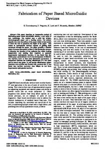
3. Simulation results I: Electric field distribution When applying a DC electric potential, the presence of the insulating obstacle creates a region of non-uniform electric field that affects particle path lines by means of negative dielectrophoretic effects. Figures (1c) and (1d) show a close view the electric field norm in both of devices. As can be seen due to the presence of the insulating obstacle, a high electric field density region is produced in the corner of obstacle (circle lines in Figures 1(c) and 1(d)) which imparts a DEP force on particles flowing down the channel thus, altering their trajectory in toward one of the two outlets. In Figure (1d) the norm of electric field distributed on six obstacles and therefore the magnitude of electric field is reduced on the obstacles. The high electric field in turn causes high Joule heating. Therefore multistep design is better when we use bio-particles in separation due to less Joule heating. Increase in Joule heating causes damage to the bio particles.
Figure 1: (a) and (b) Schematic design one and multi-step iDEP (c) and (d) Electric field distribution in one and multi-step iDEP
II: Velocity Field distribution Figures 2(a) and 2(b) show the magnitude velocity in two designs. As can be seen around the corner of insulators the magnitude of velocity is maximum and particle experienced a gradient of velocity
(1393 ﺧﺮﺩﺍﺩ1 ﺍﺭﺩﻳﺒﻬﺸﺖ ﻭ31 ) ﻣﻘﺎﻟﻪ ﻧﺎﻣﻪ ﺑﻴﺴﺖ ﻭ ﻳﻜﻤﻴﻦ ﻛﻨﻔﺮﺍﻧﺲ ﺑﻬﺎﺭﻩ ﻓﻴﺰﻳﻚ
53 :ﺷﻤﺎﺭﻩ ﻣﻘﺎﻟﻪ
on the corner. The maximum velocity in one-step insulator is 76 (μm/s) and in the multi-step is 58 (μm/s). Little difference in velocity magnitude is due to longer path of flow in the multi-step insulator. Deflection of particles in the corner of insulator due to DEP force is enhanced in the present of gradient of velocity magnitude. III: Particle trajectory Particle trajectory simulated as time dependent by using of electric field and laminar flow results in previous section. Figures 2(c) and 2(d) show the particle trajectory in one-step and multi-step devices. The particle size is 10 (μm) and 15 (μm). As mentioned inlets (I) and (II) have electric potential 150 (v) and 170 (v) and outlets (III) and (IV) are ground. As can be seen 15(μm) and 10 (μm) particles are collected in the inlet (III) and (IV) respectively. Movement of 15 (μm) into the inlet (III) is due to more DEP force on 15 (μm) than 10 (μm) particle.
Figure 2: (a) and (b) Velocity magnitude distribution in one and multi-step insulators. (c) and (d) Particle trajectory in one and multi-step insulators
Conclusions Particle trajectory in two devices includes one-step and multi-step insulator was investigated as numerically. At first Laplace and Naier-stokes equations solved as stationary mode. In following particle trajectory was solved with regarding dielectrophoresis and electrokinetice force as time-dependent mode. Results show electric field distribution and velocity magnitude are maximum on the corner of the insulators. Both of devices have similar results for particle tracing particles 10 (μm) and 15 (μm) under electric potential 150 (v) and 170 (v), but maximum electric field in multi-step insulator is less than one-step and therefore produced less Joule heating.
References [1] Lapizco‐Encinas, B. H., Simmons, B. A., Cummings, E. B., & Fintschenko, Y., 2004. “Insulator‐based dielectrophoresis for the selective concentration and separation of live bacteria in water”. Electrophoresis, 25(10‐11), Jun, pp. 1695-1704. [2] Ozuna‐Chacón, S., Lapizco‐Encinas, B. H., Rito‐Palomares, M., Martínez‐Chapa, S. O., & Reyes‐Betanzo, C., 2008. “Performance characterization of an insulator‐based dielectrophoretic microdevice”. Electrophoresis, 29(15), Jul, pp. 3115-3122. [3] A.R. Minerick, in: D. Li (Ed.), Encyclopedia of Micro- & Nanofluidics, Springer, Berlin, Heidelberg, New York, 2008. Pethig, R., & Markx, G. H., 1997. “Applications of dielectrophoresis in biotechnology. Trends in biotechnology, 15(10), Oct, 426-432