A shading language built into the API also permits the lifting .... With a metaprogramming API, precompiled shader pro- ...... http://www.ati.com/online/sdk. 5.
Graphics Hardware (2002), pp. 1–12 Thomas Ertl, Wolfgang Heidrich, and Michael Doggett (Editors)
Shader Metaprogramming Michael D. McCool, Zheng Qin, and Tiberiu S. Popa Computer Graphics Lab, School of Computer Science, University of Waterloo, Waterloo, Ontario, Canada
Abstract Modern graphics accelerators have embedded programmable components in the form of vertex and fragment shading units. Current APIs permit specification of the programs for these components using an assembly-language level interface. Compilers for high-level shading languages are available but these read in an external string specification, which can be inconvenient. It is possible, using standard C++, to define a high-level shading language directly in the API. Such a language can be nearly indistinguishable from a special-purpose shading language, yet permits more direct interaction with the specification of textures, attributes, and parameters, simplifies implementation, and enables on-the-fly generation, manipulation, and specialization of shader programs. A shading language built into the API also permits the lifting of C++ host language type, modularity, and scoping constructs into the shading language without any additional implementation effort. Categories and Subject Descriptors (according to ACM CCS): I.3.7 [Computer Graphics]: Three-Dimensional Graphics and Realism; Color, shading, shadowing, and texture
1. Introduction Specialized shading languages have been available for a long time in offline renderers, most prominently in Renderman3, 10 . Recently, real-time graphics accelerators have been targeted with shading language compilers20, 26, 29 , new techniques have been found to implement sophisticated lighting models using a relatively small number of programmable operations12, 13, 21 , and vendors have begun to implement and expose explicitly programmable components4, 19 in their latest accelerators. To date, the programming model exposed in the APIs for these programmable components has been at the level of assembly language, at best. However, proposals for OpenGL 2.01 and DX923 both call for a high-level shading language to be an integral part of the API, replacing or superceding previously hard-coded functionality. Most shading languages defined so far place the shader program in a string or file and then implement a relatively traditional assembler or compiler to convert this specification to a machine language representation. Using a separate language has some advantages—a “little language” can be more tightly focused10, 14 , shaders can be managed as “assets”—but using a custom language has problems c The Eurographics Association 2002.
too. First, although the shader programs themselves can be simple, binding them to the application program can be a nuisance. Many of the extensions to OpenGL required to support shaders in UNC’s PixelFlow system, for instance, were concerned with named parameter declaration and management16, 18, 24, 25 . Second, due to limitations on the implementation effort that can reasonably be expended, custom shading languages usually will not be as powerful as full programming languages. They often may be missing important features such as modularity and typing constructs useful for organizing complex multipart shaders. Additional useful features, such as shader specialization9 , have to be explicitly provided for by the language and shader compiler. It is possible instead to use the features of standard C++ to define a high-level shading language directly in the API, without once having to resort to the use of string manipulation. Basically, sequences of calls into an API can interpreted as a sequence of words in a “language”. Parsing of the API token sequence may be necessary, however, to support the expressions and structured control constucts used in modern high-level languages. Fortunately, with appropriate syntatic sugaring provided by operator overloading, the ordinary semantics of C++ can be use to automatically parse arithmetic
McCool, Qin, and Popa / Shader Metaprogramming
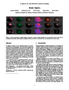
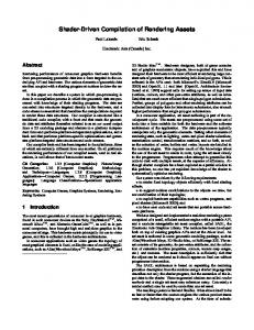
Figure 1: Some images generated by shader metaprograms. From left to right: Phong lighting model, anisotropic satin BRDF via homomorphic factorization, marble and wood implemented using different parameters with the parameterized noise shader, and finally the Julia set (just the texture, no lighting).
expressions during application program compilation. Since the parser in the API does not need to deal with expressions, the remaining parsing job is simplified. Preprocessor macros can also be defined so “keywords” can be used in place of API calls to specify control construct tokens. The result is a high-level embedded shading language which is nearly indistinguishable from a custom shading language. However, since this language is embedded in the application language, more direct interaction with the specification of textures, attributes, and parameters is possible, and shader programs can be symbolically manipulated to implement “advanced” features like specialization9 in a natural way. We call this approach a metaprogramming API. Metaprogramming is the use of one program to generate or manipulate another. Metaprogramming approaches are in fact quite common. Operating systems, compilers, assemblers, linkers, and loaders are all metaprograms. Template metaprogramming uses the rewriting semantics of C++ templates as a simple functional language to generate more efficient numerical C++ code30 (this, however, is not what we do). Currying, or the partial specification of the parameters of a function generating a new function with fewer parameters, is a fundamental capability in many functional languages. It is usually implemented using deferred execution but can also be implemented using dynamic incremental compilation of specialized functions17 . This leads to more efficient execution if the curried function is used enough to amortize the cost of compilation. Metaprogramming has also been used extensively, especially in the functional and logic programming language community, to build specialized embedded languages7 . Metaprogramming has been used to dynamically specify programs for practical programmable embedded systems, in particular for programming protocol handlers in network systems8 . Specialized C compilers have even been implemented that explicitly support an operator algebra for metaprogramming28 . Our approach does not require specialized extensions to the compiler, just exploitation of standard C++ features and an appropriate library, but it could support a similar algebra for manipulating shaders. Although we do not consider it further here, the metaprogramming API approach could be used to program other embedded systems, for instance, the DSP engines on sound cards or printer and display engines. It could also be used to
implement host-side metaprogramming and a structured application of “self-modifying code”, which could have major performance benefits (with a suitable optimizing backend) for graphics and multimedia applications5 . With a metaprogramming API, precompiled shader programs could still be used in the traditional manner simply by compiling and running a C++ program that defines an appropriate shader and dumps a compiled binary representation of it to a file. This approach could be used to invoke shaders when using an application language other than C++, such as Java or Fortran. A C++ compiler and some wrapper code would simply replace the specialized separate shader compiler. However, parameter naming and binding are simplified if the application program and the shader program are compiled together, since objects defining named parameters and textures can be accessed by the shader definition directly. Compilation of shader programs can be very fast, even with optimization, and doing it at runtime lets the program adapt to variable hardware support (important in a plug-and-play context). In the following, therefore, we will assume that the application program is also written in C++ and that shader compilation happens on the fly. We have implemented a high-level shading language/API of this nature on top of our “prototype graphics accelerator”, SMASH22 . SMASH has an OpenGL-like low-level Ccompatible API, whose calls are indicated with the prefix sm. Calls and types for the high-level C++ shader library (which is intended ultimately to be independent of SMASH) are indicated with the prefixes sh and Sh, respectively. The shading unit simulator for SMASH executes a machine language similar to that specified for DX9 or NVIDIA’s vertex shaders, but with some straightforward extensions to support noise functions and conditional branching, features we expect to see in future generations of hardware. The most recent version (0.5) of SMASH’s low-level shader API, which the high-level shader API “compiles to”, is function call-based in the style of ATI’s OpenGL vertex shader extensions4 . In the SMASH 0.5 API, each assembly language instruction is specified using a call such as “smADD(r,a,b)” and 4-tuple registers are allocated in turn using explicit API calls. However, in this document, we focus on the C++ shader library. c The Eurographics Association 2002.
McCool, Qin, and Popa / Shader Metaprogramming
In Section 2 we describe how our parser generates and manages a parse tree from the shader program described in the API. Once this is done, code generation proceeds essentially as in other shading language compilers targetting graphics accelerators (register allocation, optimization, etc.) so we do not go into great detail for this phase. Section 3 describes how named parameters and unnamed attributes are managed and bound to shader invocations. Section 4 describes in more detail our testbed, whose streaming-packet architecture makes possible the simple but flexible vertex attribute binding mechanism we use. Section 5 demonstrates the expressive power of our shading language/API by working through a number of examples. Using these examples, we show how modularity, scope, and control constructs in the application program can be “lifted” via metaprogramming into the shading language.
2. Parsing String based shading languages need a separate parsing step, usually based on an LR grammar parser-compiler such as YACC or Bison, to convert the syntax of the shader program to a parse tree. However, using a metaprogramming API, the shader program is specified using a sequence of function calls originating directly in the application program. The API then interprets this sequence of calls as a set of symbolic tokens to be used to generate a parse tree. Once built, a parse tree can in turn be compiled into machine language, or calls to a lower-level API to generate machine language, by an on-the-fly compiler backend in the API driver library. Expressions in a shading language can be parsed and typechecked at the application program’s compile time using operator overloading. To do this, overloaded operator functions are defined that construct symbolic parse trees for the expressions rather than executing computations directly. The “variables” in the shader are in fact smart reference-counting pointers to nodes in directed acyclic graphs representing expressions symbolically. Each operator function allocates a new node and uses smart pointers to refer to its children. The reference-counting smart pointers implement a simple garbage collection scheme which in this case is adequate to avoid memory leaks (expressions cannot be given that result in parse trees containing cycles). Compiling expressions in this way eliminates a large chunk of the grammar for the shading language. The API gets passed a complete parse tree for expressions directly, and does not have to build it itself by parsing a flat sequence of tokens. Each assignment in sequence is recorded as a statement in the shader program and buffered until the entire sequence of commands has been received. When the shader program is complete, code generation and optimization is performed by the driver, resulting internally in machine language which is prepared for downloading to the specified shader unit when the shader program is bound. Eventually, when shading units support control conc The Eurographics Association 2002.
structs, the shading language can be extended with shader library calls that embed tokens for control keywords in the shader statement sequence: shIF(cond), shWHILE(cond), shENDIF(), etc. Complex statements are received by the shading library API as a sequence of such calls/tokens. For instance, a WHILE statement would be presented to the API as an shWHILE(cond) function call (note the argument, which refers to a parse tree for the expression used to evaluate the condition), a sequence of other calls, and a matching smENDWHILE() call. These function calls can be wrapped in macros to make the syntax slightly cleaner (i.e. to hide semicolons and function call parenthesis): #define #define #define #define #define #define #define #define #define #define
SH_IF(cond) SH_ELSEIF(cond) SH_ELSE SH_ENDIF SH_WHILE(cond) SH_ENDWHILE SH_DO SH_UNTIL(cond) SH_FOR(init,cond,inc) SH_ENDFOR
shIF(cond); shELSEIF(cond); shELSE(); shENDIF(); shWHILE(cond); shENDWHILE(); shDO(); shUNTIL(cond); shFOR(init,cond,inc); shENDFOR();
We can also make the declarations of shaders themselves somewhat cleaner: #define SH_BEGIN_SHADER(level) #define SH_END_SHADER
shBeginShader(level); shEndShader();
Since expression parsing (and type checking) is done by C++ at the compile time of the host language, all that is needed to parse structured control constructs is a straightforward recursive-descent parser. This parser will traverse the buffered token sequence when the shader program is complete, generating a full parse tree internally. Code generation can then take place in the usual way. Although true conditional execution and looping were not commercially available at the time this paper was written, such control constructs can theoretically be implemented efficiently in the context of a long texture lookup latency with either a recirculating pipeline or a multithreaded shading processor. 3. Parameters and Attributes It is convenient to support two different techniques for passing values to shaders. For semi-constant “uniform” values, the use of named variables whose values can be changed at any time and in any order is convenient. We will give uniform variables the special name of parameters and will reserve the word attributes for values specified per-entity (vertex or fragment). A named parameter is created simply by constructing an object of an appropriate type outside of a shader definition: // create named matrix parameters ShMatrix3x4f modelview; ShMatrix4x4f perspective; // create named light parameters ShColor3f light_color; ShPoint3f light_position;
McCool, Qin, and Popa / Shader Metaprogramming
The constructor of these classes, when called outside an open shader definition, makes appropriate calls to allocate state for these parameters, and the destructor makes calls to deallocate this state. When a shader definition uses a parameter the compiler notes this fact and arranges for the current value of each such parameter to be bound to a constant register in the shader unit when the shader program is loaded. This is done automatically, so all the user has to do is declare the parameter, use it in a shader, and set the value appropriately when necessary. Assignment to parameters generates an error when used inside a shader definition (parameters are read-only in shaders), but is allowed to modify the parameter’s value outside a shader definition. For shader arguments whose values change at every vertex or fragment, we have chosen to make the order of specification of these variables important, and follow the ARB convention of calling them “attributes”. Attributes can be considered equivalent to unnamed arguments used in function calls in C/C++, while parameters are like external variables. Note that it is not considered an especial hardship to remember the order of function call arguments in ordinary C/C++ functions. In immediate mode in SMASH, attribute binding calls incrementally add attributes to a packet, which is sent off as a vertex packet when the vertex call is made (after adding the last few values given in the vertex call itself). For instance, suppose we want to pass a tangent vector, a normal, and a texture coordinate to a vertex shader at the vertices of a single triangle. In immediate mode we would use calls of the form smBegin(SM_TRIANGLES); smVector3fv(tangent[0]); smNormal3fv(normal[0]); smTexCoord2fv(texcoord[0]); smVertex3fv(position[0]); smVector3fv(tangent[1]); smNormal3fv(normal[1]); smTexCoord2fv(texcoord[1]); smVertex3fv(position[1]); smVector3fv(tangent[2]); smNormal3fv(normal[2]); smTexCoord2fv(texcoord[2]); smVertex3fv(position[2]); smEnd();
The generic attribute binding call smAttrib* can be used in place of smVector*, smNormal*, etc. Vertex attribute arrays are of course also supported for greater efficiency. When vertex attributes of different lengths are mixed, for instance, bytes, short integers, and floats, the current attribute pointer is always rounded up to the next alignment boundary. However, attributes are always unpacked into singleprecision floats in the shading units. Support for variableprecision attributes just reduces bandwidth requirements. Declarations inside every shader definition provide the necessary information to enable the system to unpack input attributes and pack output attributes.
Under OpenGL, attributes can be bound by both type and order. For instance, the first texture coordinate attribute declared can be mapped to the first texture coordinate, the first attribute declared can be mapped to the first vertex attribute, and so forth. An OpenGL binding will however add some restrictions. For instance, under OpenGL, only one normal can be specified for a vertex; in SMASH, any number of vertex attributes of any type are permitted. Finally, the driver must also ensure that when a shader is bound that any texture objects it uses are also bound. Like parameters, a texture just has to be mentioned in a shader for it to be used. No other declaration is necessary: the API will allocate texture units and ensure the texture is loaded when needed. The C++ level of the API also uses classes to wrap low-level texture objects. Operator overloading of [] is used so that within a shader definition a texture lookup can be specified as if it were an array access. In a sense, textures are just “grid-valued parameters” with support for interpolation and filtering.
4. Testbed Our high-level shader API is built on top of SMASH, a testbed we have developed to experiment with possible next-generation graphics hardware features and their implementation. This system is modular, and is built around modules communicating over point-to-point channels using sequences of self-identifying variable-length packets. Pipelines can be built with any number of shading processors or other types of modules (such as rasterizers or displacement units) chained together in sequence or in parallel. The API has to deal with the fact that any given SMASH system might have a variable number of shading units, and that different shading units might have slightly different capabilities (for instance, vertex shaders might not have texture units, and fragment shaders may have a limited number of registers and operations). These restrictions are noted when a system is built and the shader compiler adapts to them. The API currently identifies shaders by pipeline depth. In the usual case of a vertex shader and a fragment shader, the vertex shader has depth 0 and the fragment shader has depth 1. When a shader program is downloaded, the packet carrying the program information has a counter. If this counter is non-zero, it is decremented and the packet is forwarded to the next unit in the pipeline. Otherwise, the program is loaded and the packet absorbed. Modules in the pipeline that do not understand a certain packet type are also supposed to forward such packets without change. A flag in each packet indicates whether or not packets should be broadcast over parallel streams or not; shader programs are typically broadcast. In this fashion shader programs can be sent to any shader unit in the pipe. Shader programs in SMASH are defined using a syntax similar to that of the shader library, but using a lower-level c The Eurographics Association 2002.
McCool, Qin, and Popa / Shader Metaprogramming
assembly language that operates on explictly allocated register objects. Sequences of tokens defining an assembly program are defined using a sequence of API calls (one for each instruction or branch target point) inside a matched pair of smBeginShader(shaderlevel) and smEndShader() calls. Once defined, a shader can be loaded using the smBindShader(shaderobject) call. When a program is running on a shader unit, vertex and fragment packets are rewritten by that unit. The system supports packets of length up to 255 words, not counting a header which gives the type and length of each packet. Each word is 32 bits in length, so shaders can have up to 255 single-precision inputs and outputs. Type declarations for shader attribute declarations can be used to implicitly define packing and unpacking of shorter attributes to conserve bandwidth when this full precision is not necessary. Other units, such as the rasterizer and compositing module, also need to have packets formatted in a certain way to be meaningful; in particular, the rasterizer needs the position of a vertex in a certain place in the packet (at the end, consisent with the order of attribute and vertex calls). These units also operate by packet rewriting; for instance, a rasterizer parses sequences of vertex packets according to the current geometry mode, reconstructs triangles from them, and converts them into streams of fragment packets.
is the normalized surface normal, I` is the light source intensity, r` is the distance to light source, and kd , ks , and q are parameters of the lighting model. We will implement this using per-pixel computation of the specular lobe and texture mapping of kd and ks . 5.1.1. Vertex Shader This shader computes the model-view transformation of position and normal, the projective transformation of viewspace position into device space, the halfvector, and the irradiance. These values will be ratiolinearly interpolated by the rasterizer and the interpolated values will be assigned to the fragments it generates. The rasterizer expects the last parameter in each packet to be a device-space 4-component homogeneous point. ShShader phong0 = SH_BEGIN_SHADER(0) { // declare input vertex parameters // unpacked in order given ShInputTexCoord2f ui; // texture coords ShInputNormal3f nm; // normal vector (MCS) ShInputPoint3f pm; // position (MCS) // declare outputs vertex parameters // packed in order given ShOutputVector3f hv; // half-vector (VCS) ShOutputTexCoord2f uo(ui); // texture coords ShOutputNormal3f nv; // normal (VCS) ShOutputColor3f ec; // irradiance ShOutputPoint4f pd; // position (HDCS)
5. Examples The following sections present example shaders that, while useful in their own right, are each meant to show some useful aspect of the metaprogramming API and shading language we propose. In Section 5.1 we implement the Blinn-Phong lighting model, then modify it to show how the modularity and scoping constructs of the host language can be “lifted” into the shading language. Section 5.2 shows an alternative method for building lighting models, but also combines several materials using material mapping. We use this example to demonstrate the control constructs of the shading language, and also show how the control constructs of the host language can be lifted into the shading language if necessary. Section 5.3 demonstrates the use of the noise function to implement wood and marble shaders. Noise can be either provided by the underlying shading system or implemented by the compiler using precomputed textures, without change to the high-level shader (although implementing noise using textures will, of course, use up texture units). Section 5.4 demonstrates a complex computation using a loop: the Julia set fractal. 5.1. Modified Phong Lighting Model Consider the modified Blinn-Phong lighting model15 : � ˆ q max(0, (nˆ · ˆl))I` /r`2 Lo = kd + ks (nˆ · h) where vˆ is the normalized view vector, ˆl is the normalized light vector, hˆ = norm(ˆv + ˆl) is the normalized half vector, nˆ c The Eurographics Association 2002.
// compute VCS position ShPoint3f pv = modelview | pm; // compute DCS position pd = perspective | pv; // compute normalized VCS normal nv = normalize(nm | adjoint(modelview)); // compute normalized VCS light vector ShVector3f lvv = light_position - pv; ShAttrib1f rsq = 1.0/(lvv|lvv); lvv *= sqrt(rsq); // compute irradiance ShAttrib1f ct = max(0,(nv|lvv)); ec = light_color * rsq * ct; // compute normalized VCS view vector ShVector3f vvv = -normalize(ShVector3f(pv)); // compute normalized VCS half vector hv = normalize(lvv + vvv); } SH_END_SHADER;
We do not need to provide prefixes for the utility functions normalize, sqrt, etc. since they are distinguished by the type of their arguments. In our examples we will also highlight, using boldface, the use of externally declared parameter and texture objects. The types ShInput* and ShOutput* are subclasses of the basic variable types whose constructors call input/output allocation functions in the API. The order in which these constructors are called provides the necessary information to the API on the order in which these values should be unpacked from input packets and packed into output packets. Temporary registers can also be declared explictly as shown. The same constructors are used to declare global parameters as are used to declare temporaries; the fact temporary
McCool, Qin, and Popa / Shader Metaprogramming
allocators are called inside a shader distinguishes them. Of course the compiler will declare more temporary registers internally in order to implement expression evaluation, and will optimize register allocation as well.
ter. Ideally, we would antialias this lighting model by clamping the exponent as a function of distance and curvature2 , but we have not implemented this functionality in this shader to keep the example simple.
The library permits allocation of named transformation matrices in the same manner as other parameters. When accessing a matrix value, the matrix can be bound either as a transpose, inverse, transpose inverse, adjoint, or transpose adjoint. The adjoint (the transpose of the cofactor matrix) is useful as it is equivalent to the inverse within a scale factor (specifically, M −1 = adj M/ det M). However, we do not need to declare these bindings explicitly since simply using a object representing a named parameter or matrix is enough to bind it to the shader and for the shader library to arrange for that parameter to be sent to the shader processor when updated. The symbolic functions transpose, inverse, adjoint, etc. cause the appropriate version of the matrix to be bound to the shader. Note that the inverse is not computed at the point of use of the matrix, it is computed at the point of matrix specification. This is actually just a special case of constant folding: when expressions involving only constants and “uniform” parameters are used inside a shader, hidden parameters are automatically created representing the result of these uniform computations. It is this result that is downloaded to the shader, not the original parameters. Whenever one of the parameters involved in such an expression is modified, the host updates all dependent parameters. This applies only to parameter expressions given inside shader definitions. Outside shader definitions, expressions involving parameters are evaluated immediately and do not result in the creation of hidden dependent parameters.
ShShader phong1 = SH_BEGIN_SHADER(1) { // declare input fragment parameters // unpacked in order given ShInputVector3f hv; // half-vector (VCS) ShInputTexCoord2f u; // texture coordinates ShInputNormal3f nv; // normal (VCS) ShInputColor3f ec; // irradiance ShInputAttrib1f pdz; // fragment depth (DCS) ShInputAttrib2us pdxy; // fragment 2D position (DCS)
5.1.2. Fragment Shader This shader completes the Blinn-Phong lighting model example by computing the specular lobe and adding it to the diffuse lobe. Both reflection modes are modulated by specular and diffuse colors that come from texture maps using the previously declared texture objects phong_kd and phong_ks. In general, the notation t[u], where t is a texture object, will indicate a filtered and interpolated texture lookup, not just a simple array access (although, if the texture object access modes are set to nearest-neighbor interpolation without MIP-mapping, it can be made equivalent to a read-only array). The rasterizer automatically converts 4D homogenous device space points (specifying the positions of vertices) to normalized 3D device space points (specifying the position of each fragment). We have chosen to place the 32-bit floating-point fragment depth z first in the output packet to automatically result in the correct packing and alignment for x and y, making it easier for the compositor module following the fragment shader to find these values. The Phong exponent is specified here as a named parame-
// declare output fragment parameters // packed in order given ShOutputColor3f fc; // fragment color ShOutputAttrib1f fpdz(pdz); // fragment depth ShOutputAttrib2us fpdxy(pdxy); // fragment 2D position // compute texture-mapped Blinn-Phong model fc = phong_kd[u] + phong_ks[u] * pow((normalize(hv)|normalize(nv)),phong_exp); // multiply lighting model by irradiance fc *= ec; } SH_END_SHADER;
Since it is not needed for bit manipulation, we use the operator “|” to indicate the inner (dot) product between vectors rather than bitwise OR. We also use the operator “&” for the cross product, which has the advantage that the triple product can be easily defined. However, parentheses should be always be used around dot and cross products when they are used with other operators due to the low precendence of these operators. Matrix and matrix-vector multiplications are also indicated with the “|” operator. In matrix-vector multiplications if a vector appears on the right of the product it is interpreted as a column and if on the left as a row. For the most part this eliminates the need to explicitly specify transposes. To transform a normal you have to explicitly specify the use of the inverse and use the normal as a row vector, or specify the inverse transpose matrix and use the normal as a column vector. The adjoint can be used in place of the inverse, however, if you are going to normalize the result anyways. Adjoint and inverse operations applied to (n − 1) × n matrices return n × n results, assuming the input matrices were meant to represent affine transformations. Likewise, mismatches in size by one element (for instance, a multiplication of a 3-vector by a 3 × 4 matrix) are accepted if a homogeneous extension of the relevant point (by a 1 element) or vector (by a 0 element) would make the dimensions of the matrix multiplication valid. Use of the “*” operator on a pair of tuples (or matrices) of any type results in componentwise multiplication. Use of “*” between a 1D scalar value and any nD tuple results in scalar multiplication. 5.1.3. Modularity The Blinn-Phong model is an example of a shader program which would make a useful subprogram in other places. We c The Eurographics Association 2002.
McCool, Qin, and Popa / Shader Metaprogramming
would expect that many shaders in practice will be a combination of several standard parts. We would like to have a subprogram capability in order to be able to reuse code conveniently. The other reason for having a subprogram capability would be to save code space. Even without a subprogram capability in the shader unit itself, we can use the modularity constructs of the host language to better organize our shaders for reuse. For instance, we can better package the above Blinn-Phong shader as follows: ShColor3f phong ( ShVector3f hv, ShNormal3f nv, ShColor3f kd, ShColor3f ks, ShAttrib1f exp ) { ShAttrib1f hn = (normalize(hv)|normalize(nv)); return kd + ks * pow(hn,exp); } class Phong { private: ShShader phong0, phong1; public: ShTexture2DColor3f kd; ShColor3f ks; Phong (double exp) { ShShader phong0 = SH_BEGIN_SHADER(0) { ShInputTexCoord2f ui; ShInputNormal3f nm; ShInputPoint3f pm; ShOutputVector3f hv; ShOutputTexCoord2f uo(ui); ShOutputNormal3f nv; ShOutputColor3f ec; ShOutputPoint4f pd; ShPoint3f pv = modelview | pm; pd = perspective | pv; nv = normalize(nm | adjoint(modelview)); ShVector3f lvv = light_position - pv; ShAttrib1f rsq = 1.0/(lvv|lvv); lvv *= sqrt(rsq); ShAttrib1f ct = max(0,(nv|lvv)); ec = light_color * rsq * ct; ShVector3f vvv = -normalize(ShVector3f(pv)); hv = normalize(lvv + vvv); } SH_END_SHADER; phong1 = SH_BEGIN_SHADER(1) { ShInputVector3f hv; ShInputTexCoord2f u; ShInputNormal3f nv; ShInputColor3f ec; ShInputAttrib1f pdz; ShInputAttrib2us pdxy; ShOutputColor3f fc; ShOutputAttrib1f fpdz(pdz); ShOutputAttrib2us fpdxy(pdxy); fc = ec * phong(hv,nv,kd[u],ks,exp); } SH_END_SHADER; } void bind () { shBindShader(phong0); shBindShader(phong1); } };
c The Eurographics Association 2002.
Two kinds of modularity are used here. First, the C++ function phong is used to define the basic Blinn-Phong model. This function has arguments which are smart pointers to expressions and returns a smart pointer to an expression. Note that the classes used to declare argument and return types in this function are used to support both the “parameter” and “attribute” functionality (so a subroutine can be used both inside and outside a shader), and these classes also support automatic conversion from doubles and integers. This function can now be used in many different shaders. In fact, this is precisely how many “built-in” functions, such as normalize, sqrt, and even the expression operators, are defined. Secondly, we have wrapped the definition of a complete multistage shader in a class. Construction of a instance of this class defines the shaders; destruction deallocates them. We don’t need explicit deallocation of the subshaders since deallocation of phong0 and phong1 performs that task. We have also defined a single method, bind, to load the shader into all shader units, and have also used the class to organize the parameters and textures for this shader. We have also modified the shader somewhat, using a texture only for kd, a parameter for ks, and a definition-time constant for exp. The use of exp is especially interesting: basically, each instance of the Phong class is a specialized shader, with a different exponent compiled in for each instance (note that automatic conversion is involved here). But we could just as easily have defined exp as a parameter, ks as a texture, and so forth, without changing the definition of the phong function. In short, by embedding the shader definition language in the host language we have made all the modularity constructs of the host language available for organizing and structuring shaders. Later on, we plan to support operator overloading of “()” on shader objects to support true subroutines (using an additional SH_RETURN token to define the return value, but the same syntax as other shaders for defining input and output parameters). The interesting thing about this is that the shaders that use these subprograms do not have to know if the subshader they are “calling” is a application-language “macro”, as above, or a true subprogram on the shading unit: the syntax would be exactly the same. 5.2. Separable BRDFs and Material Mapping A bidirectional reflection distribution function f is in general a 4D function that relates the differential incoming irradiance to the differential outgoing radiance. Z
Lo (x; vˆ ) =
Ω
f (x; vˆ ← ˆl) max(0, nˆ · ˆl) Li (x; ˆl) dˆl.
Relative to a point source, which would appear as an impulse function in the above integral, the BRDF can be used as a lighting model: Lo (x; vˆ ) = f (ˆv ← ˆl; x) max(0, nˆ · ˆl) I` /r`2 .
McCool, Qin, and Popa / Shader Metaprogramming
In general, it is impractical to tabulate a general BRDF. A 4D texture lookup would be required. Fortunately, it is possible to approximate BRDFs by factorization. In particular, a numerical technique called homomorphic factorization21 can be used to find a separable approximation to any shiftinvariant BRDF: ˆ pm (ˆl) fm (ˆv ← ˆl) ≈ pm (ˆv) qm (h) In this factorization, we have chosen to factor the BRDF into terms dependent directly on incoming light direction ˆl, outˆ all exgoing view direction vˆ , and half vector direction h, pressed relative to the local surface frame. Other parameterizations are possible but this one seems to work well in many circumstances and is easy to compute. To model the dependence of the reflectance on surface position, we can sum over several BRDFs, using a texture map to modulate each BRDF. We call this material mapping: f (u; vˆ ← ˆl) =
M−1
∑
tm [u] fm (ˆv ← ˆl)
m=0 M−1
=
∑
ˆ pm [ˆl]. tm [u] pm [ˆv] qm [h]
m=0
When storing them in a fixed-point data format, we also rescale the texture maps to maximize precision: f (u; vˆ ← ˆl) =
M−1
∑
ˆ p0m [ˆl]. αm tm0 [u] p0m [ˆv] q0m [h]
m=0
5.2.1. Vertex Shader Here is a vertex shader to set up material mapping using a separable BRDF decomposition for each material. ShShader hf0 = SH_BEGIN_SHADER(0) { // declare input vertex parameters // unpacked in order given ShInputTexCoord2f ui; // texture coords ShInputVector3f t1; // primary tangent ShInputVector3f t2; // secondary tangent ShInputPoint3f pm; // position (MCS) // declare output vertex parameters // packed in order given ShOutputVector3f vvs; // view-vector (SCS) ShOutputVector3f hvs; // half-vector (SCS) ShOutputVector3f lvs; // light-vector (SCS) ShOutputTexCoord2f uo(ui); // texture coords ShOutputColor3f ec; // irradiance ShOutputPoint4f pd; // position (HDCS) // compute VCS position ShPoint3f pv = modelview | pm; // compute DCS position pd = perspective | pv; // transform and normalize tangents t1 = normalize(modelview | t1); t2 = normalize(modelview | t2); // compute normal via a cross product ShNormal3f nv = normalize(t1 & t2); // compute normalized VCS light vector ShVector3f lvv = light_position - pv; ShAttrib1f rsq = 1.0/(lvv|lvv); lvv *= sqrt(rsq); // compute irradiance
ShAttrib1f ct = max(0,(nv|lvv)); ec = light_color * rsq * ct; // compute normalized VCS view vector ShVector3f vvv = -normalize(ShVector3f(pv)); // compute normalized VCS half vector ShVector3f hv = norm(lvv + vvv); // project BRDF parameters onto SCS vvs = ShVector3f((vvv|t1),(vvv|t2),(vvv|nv)); hvs = ShVector3f((hvv|t1),(hvv|t2),(hvv|nv)); lvs = ShVector3f((lvv|t1),(lvv|t2),(lvv|nv)); } SH_END_SHADER;
5.2.2. Fragment Shader The fragment shader completes the material mapping shader by using an application program loop (running on the host, not the shader unit) to generate an unrolled shader program. A looping construct is not required in the shader program to implement this. In fact, the API does not even see the loop, only the calls it generates. We also use a shader specialization conditional that selects between cube maps and parabolic maps using introspection. If the platform supports them, we would want to use cube maps for the factors; however, parabolic maps will work on anything that supports 2D texture mapping. The shader compiler and the shading system do not have to support conditionals or a special mechanism for shader specialization, and in fact again never even sees these control constructs. Of course, such conditionals can only depend on information that is known at shader definition time. ShTexCoord3f parabolic ( ShVector3f v ) { ShTexCoord3f u; u(0) = (7.0/8.0)*v(0) + v(2) + 1; u(1) = (7.0/8.0)*v(1) + v(2) + 1; u(2) = 2.0*(v(2) + 1); return u; } ShShader hf1 = SH_BEGIN_SHADER(1) { // declare input fragment parameters // unpacked in order given ShInputVector3f vv; // view-vector (SCS) ShInputVector3f hv; // half-vector (SCS) ShInputVector3f lv; // light-vector (SCS) ShInputTexCoord2f u; // texture coordinates ShInputColor3f ec; // irradiance ShInputAttrib1f pdz; // fragment depth (DCS) ShInputAttrib2us pdxy; // fragment position (DCS) // declare output fragment parameters // packed in order given ShOutputColor3f fc; // fragment color ShOutputAttrib1f fpdz(pdz); // fragment depth ShOutputAttrib2us fpdxy(pdxy); // fragment position // intialize total reflectance fc = ShColor3f(0.0,0.0,0.0); // sum up contribution from each material for (int m = 0; m < M; m++) { ShColor3f fm; if (hf_p[m].isa(SH_TEXTURE_2D)) { // is a parabolic map fm = hf_p[m][parabolic(vv)] * hf_p[m][parabolic(lv)]; } else { // is a cube map fm = hf_p[m][vv]
c The Eurographics Association 2002.
McCool, Qin, and Popa / Shader Metaprogramming * hf_p[m][lv]; } if (hf_q[m].isa(SH_TEXTURE_2D)) { // is a parabolic map fm *= hf_q[m][parabloic(hv)]; } else { // is a cube map fm *= hf_q[m][hv]; } // sum up weighted reflectance fc += hf_mat[m][u] * hf_alpha[m] * fm; } // multiply by irradiance fc *= ec; } SH_END_SHADER;
Here the texture array objects hf_mat, hf_p, and hf_q should have been previously defined, along with the normalization factor parameter array hf_alpha. The introspection method isa checks if the texture objects hf_p and hf_q are 2D texture maps. In this case, the shader assumes the factors are stored as parabolic maps. We define the texture coordinates as homogenous coordinates (when we make a lookup in a 2D texture using a 3D coordinate the last coordinate is automatically interpreted as a homogeneous coordinate). Otherwise, we assume that the texture maps are cube maps so unnormalized direction vectors can be used directly as texture coordinates. Note also the use of the () operator on tuples to represent swizzling, component selection, and write masking. This is implemented by defining a function that adds a swizzle/mask object to the top of the expression parse tree; this object is interpreted differently depending on whether it appears on the left or right side of an expression. It can have one to four integer arguments to represent swizzling.
// packed in order given ShOutputColor3f fc; // fragment color ShOutputAttrib1f fpdz(pdz); // fragment depth ShOutputAttrib2us fpdxy(pdxy); // fragment position // intialize total reflectance fc = ShColor3f(0.0,0.0,0.0); // sum up contribution from each material for (int m = 0; m < M; m++) { SH_IF(hg_mat[m][u](3) > 0.0) { ShColor3f fm; if (hf_p[m].isa(SH_TEXTURE_2D)) { fm = hf_p[m][parabolic(vv)] * hf_p[m][parabolic(lv)]; } else { fm = hf_p[m][vv] * hf_p[m][lv]; } if (hf_q[m].isa(SH_TEXTURE_2D)) { fm *= hf_q[m][parabolic(hv)]; } else { fm *= hf_q[m][hv]; } fc += hf_mat[m][u] * hf_alpha[m] * fm; } SH_ENDIF } // multiply by irradiance fc *= ec; } SH_END_SHADER;
The braces shown around the body of the SH_IF/SH_ENDIF are optional, but give a host-language name scope that corresponds to the shading language name scope for values declared inside the body of the SH_IF statement. 5.3. Parameterized Noise To implement marble, wood, and similar materials, we have used the simple parameterized model for such materials proposed by John C. Hart et al.11 . This model is given by
5.2.3. Run-Time Conditional Execution If the underlying shader unit supports it, we can also use run-time shader conditionals to avoid unneeded execution of parts of shaders. On a system that does not directly support conditionals, a mux-select, multiplication by zero, or tex-kill (on a multipass implementation) would be used, as appropriate, but of course some of these options would be less efficient than true conditional execution. However, the real benefit of true conditional execution in this example would be that we can avoid filling up the texture cache and using memory bandwidth for textures that will not be used. A SIMD execution scheme that inhibited instructions from having an effect but still used clock cycles for them would be sufficient to gain this specific benefit. ShShader hf1 = SH_BEGIN_SHADER(1) { // declare input fragment parameters // unpacked in order given ShInputVector3f vv; // view-vector (SCS) ShInputVector3f hv; // half-vector (SCS) ShInputVector3f lv; // light-vector (SCS) ShInputTexCoord2f u; // texture coordinates ShInputColor3f ec; // irradiance ShInputAttrib1f pdz; // fragment depth (DCS) ShInputAttrib2us pdxy; // fragment position (DCS) // declare output fragment parameters
c The Eurographics Association 2002.
N−1
t(x) =
∑ αi |n(2i x)|,
i=0 T
u = x Ax + t(x), kd (x) = cd [u], ks (x) = cs [u]. where n is a bandlimited noise function such as Perlin noise27 , t is the “turbulence” noise function synthesized from it, A is a 4×4 symmetric matrix giving the coefficients of the quadric function xT Ax, cd and cs are 1D MIP-mapped texture maps functioning as filtered color lookup tables, and x is the model-space (normalized homogeneous) position of a surface point. The outputs need to be combined with a lighting model, so we will combine them with the Phong lighting model (we could just as easily have used separable BRDFs and material maps, with one color lookup table for each). Generally speaking we would use fractal turbulence and would have αi = 2i ; however, for the purposes of this example we will permit the αi values to vary to permit further per-material noise shaping and will bind them to named parameters. Likewise, various simplifications would be possible if we fixed A (marble requires only a linear term, wood
McCool, Qin, and Popa / Shader Metaprogramming
only a cylinder) but we have chosen to give an implementation of the more general model and will bind A to a named parameter. The low-level SMASH API happens to have support for Perlin noise, generalized fractal noise, and generalized turbulence built in, so we do not have to do anything special to evaluate these noise functions. If we had to compile to a system without noise hardware, we would store a periodic noise function in a texture map and then could synthesize aperiodic fractal noise by including appropriate rotations among octaves in the noise summation. 5.3.1. Vertex Shader The vertex shader sets up the Phong lighting model, but also computes half of the quadric as a linear transformation of the model space position. This can be correctly ratiolinearly interpolated. ShShader pnm0 = SH_BEGIN_SHADER(0) { // declare input vertex parameters // unpacked in order given ShInputNormal3f nm; // normal vector (MCS) ShInputPoint3f pm; // position (MCS) // declare output vertex parameters // packed in order given ShOutputPoint4f ax; // coeffs x MCS position ShOutputPoint4f x; // position (MCS) ShOutputVector3f hv; // half-vector (VCS) ShOutputNormal3f nv; // normal (VCS) ShOutputColor3f ec; // irradiance ShOutputPoint4f pd; // position (HDCS) // transform position ShPoint3f pv = modelview | pm; pd = perspective | pv; // transform normal nv = normalize(nm | inverse(modelview)); // compute normalized VCS light vector ShVector3f lvv = light_position - pv; ShAttrib1f rsq = 1.0/(lvv|lvv); lvv *= sqrt(rsq); // compute irradiance ShAttrib1f ct = max(0,(nv|lvv)); ec = light_color * rsq * ct; // compute normalized VCS view vector ShVector3f vvv = -normalize(ShVector3f(pv)); // compute normalized VCS half vector hv = norm(lvv + vvv); // projectively normalize position x = projnorm(pm); // compute half of quadric ax = quadric_coefficients | x; } SH_END_SHADER;
5.3.2. Fragment Shader The fragment shader completes the computation of the quadric and the turbulence function and passes their sum through the color lookup table. Two different lookup tables are used to modulate the specular and diffuse parts of the lighting model, which will permit, for example, dense dark wood to be shinier than light wood (with the appropriate entries in the lookup tables). ShShader pnm1 = SH_BEGIN_SHADER(1) { // declare input fragment parameters
// unpacked in order given ShInputPoint4f ax; // ShInputPoint4f x; // ShInputVector3f hv; // ShInputNormal3f nv; // ShInputColor3f ec; // ShInputAttrib1f pdz; // ShInputAttrib2us pdxy; //
coeffs x MCS position position (MCS) half-vector (VCS) normal (VCS) irradiance fragment depth (DCS) fragment 2D position (DCS)
// declare output fragment parameters // packed in order given ShOutputColor3f fc; // fragment color ShOutputAttrib1f fpdz(pdz); // fragment depth ShOutputAttrib2us fpdxy(pdxy); // fragment 2D position // compute texture coordinates ShTexCoord1f u = (x|ax) + turbulence1(pnm_alpha,x); // compute Blinn-Phong lighting model fc = pnm_cd[u] + pnm_cs[u] * pow((normalize(hv)|normalize(nv)),phong_exp); // multiply by irradiance fc *= ec; } SH_END_SHADER;
Two things are worth pointing out here. First, we have not given the dimensionality of pnm_alpha. In the underlying system, it must be at most 4, so it can fit in a single register. However, the high-level language compiler can easily synthesize noise functions with more octaves given the ability to do one with four: 3
t0:3 (u) =
∑ αi |n(2i u)|,
i=0 7
t0:7 (u) =
∑ αi |n(2i u)|
i=0 3
=
3
∑ αi |n(2i u)| + ∑ α j+4 |n(24 2 j u)|
i=0
j=0
4
= t0:3 (u) + t4:7 (2 u). The function turbulence1 given above is in fact a template function that does this based on the dimensionality of its first argument. It also calls a noise function of the appropriate dimensionality based on the dimensionality of its second argument. The number in the name indicates the dimensionality of the result. The second thing to point out is that on hardware accelerators without built in noise functions, noise can be either stored in textures or generated from a small subprogram. All that is really needed is the ability to hash a point in space to a determinisitic but random-seeming value. This can be supported using a 1D nearest-neighbour texture lookup (Perlin’s original implementation of his noise function in fact uses such an approach for implementing a hash function6, 27 ) or ideally a special “hash” instruction. The rest of the arithmetic can be done using arithmetic operations already supported by the shading unit. The main point really of this example is this: we can’t tell if turbulence1 is a builtin function or something supported by the compiler, which supports backward compatibility as new features are added to graphics accelerators. In fact, the implementation of the turbulence1 function could use introspection to see if c The Eurographics Association 2002.
McCool, Qin, and Popa / Shader Metaprogramming
the target accelerator the program in running on at the moment the shader is defined supports noise functions directly or if one needs to be synthesized. 5.4. Julia Set This example demonstrates the use of a conditional loop. We assume that a 1D texture map julia_map and a scale factor parameter julia_scale have been previously defined to map from the iteration count to the color of the final output and also that a parameter julia_max_iter has been defined to specify the maximum number of iterations permitted. The 2D (complex-valued) parameter julia_c can be manipulated to give different Julia sets. 5.4.1. Vertex Shader The product of the perspective and modelview matrix parameters will be precomputed on the host as part of parameter (constant) folding, not at runtime in the shading unit. ShShader julia0 = SH_BEGIN_SHADER(0) { // declare input vertex parameters // unpacked in order given ShInputTexCoord2f ui; // texture coords ShInputPoint3f pm; // position (MCS) // declare outputs vertex parameters // packed in order given ShOutputTexCoord2f uo(ui); // texture coords ShOutputPoint4f pd; // position (HDCS) // compute DCS position pd = (perspective | modelview) | pm; } SH_END_SHADER;
5.4.2. Fragment Shader ShShader julia1 = SH_BEGIN_SHADER(1) { // declare input fragment parameters // unpacked in order given ShInputTexCoord2f u; // texture coordinates ShInputAttrib1f pdz; // fragment depth (DCS) ShInputAttrib2us pdxy; // fragment 2D position (DCS) // declare output fragment parameters // packed in order given ShOutputColor3f fc; // fragment color ShOutputAttrib1f fpdz(pdz); // fragment depth ShOutputAttrib2us fpdxy(pdxy); // fragment 2D position ShAttrib1f i = 0.0; SH_WHILE((u|u) < 2.0 && i < julia_max_iter) { u(0) = u(0)*u(0) - u(1)*u(1); u(1) = 2*u(0)*u(1); u += julia_c; i++; } SH_ENDWHILE;
shape of the Julia set can be manipulated by changing the julia_c parameter, and the resolution can be increased by increasing julia_max_iter, although at the cost of increased computation. Eventually we also run out of precision, so if anything this shader would be a good visual indicator of the precision available in a fragment shader implementation. The texture map julia_map and the parameter julia_scale can be used to colour the result in various interesting ways. In theory, we could use an integer for the iteration counter i, but we assume at present that shader evaluation is based only on floating-point numbers. 6. Conclusions We have presented techniques for embedding a high-level shading language directly in a C++ graphics API. This requires run-time compilation of shaders, but in return provides a great deal of flexibility in the specification of shaders. The control and modularity constructs of C++ can be used in various ways to provide similar capabilities in the shading language. In particular, the scope rules of C++ can be used to control which “uniform” parameters get bound to which shaders, functions in C++ can be used to implement macros for the shading language, and classes can be used to organize shaders and their parameters, all without any additional work by the shader compiler. A string-based shading language and a C++ shading language might coexist in practice. However, the “string” based shading language could be implemented by invoking the C++ compiler with a stub mainline program that compiles the shader and outputs a compiled representation for later reloading, or an object file that could be used for dynamic linking. Although we have built our system on top of an experimental graphics system (SMASH) we feel that a similar shading language could easily be built for OpenGL2.0 and DX9. This would not require modification to these APIs — in fact, the restriction to C++ is problematic for Java and FORTRAN embeddings of APIs, so lower-level APIs would be required at any rate — but could be implemented as a library. As soon as sufficiently powerful graphics hardware is available, we plan to target these platforms. For maximum efficiency, ideally the backend API should provide the ability to directly specify shader programs in an intermediate language via a function call interface to avoid the need for string manipulation. Acknowledgements
// send increment through lookup table fc = julia_map[julia_scale*i]; } SH_END_SHADER;
We do not have complex numbers built in (although it would be feasible to define appropriate subclassed types and overloaded operators) so we write out the Julia set iteration explicitly and use two-vectors to store complex numbers. The c The Eurographics Association 2002.
This research was funded by grants from the National Science and Engineering Research Council of Canada (NSERC), the Centre for Information Technology of Ontario (CITO), the Canadian Foundation for Innovation (CFI), the Ontario Innovation Trust (OIT), and finally the Bell University Labs initiative.
McCool, Qin, and Popa / Shader Metaprogramming
References
16. Anselmo Lastra, Steven Molnar, Marc Olano, and Yulan Wang. Real-time programmable shading. Symposium on Interactive 3D Graphics, pages 59–66, 1995.
1.
3DLabs. OpenGL 2.0 Shading Language White Paper, 1.2 edition, February 2002.
2.
John Amanatides. Algorithms for the detection and elimination of specular aliasing. Graphics Interface, pages 86–93, May 1992.
17. Peter Lee and Mark Leone. Optimizing ML with Run-Time Code Generation. SIGPLAN Conference on Programming Language Design and Implementation, pages 137–148, 1996.
3.
Anthony A. Apodaca and Larry Gritz. Advanced RenderMan: Creating CGI for motion pictures. Morgan Kaufmann, 2000.
18. Jon Leech. OpenGL extensions and restrictions for PixelFlow. Technical Report TR98-019, Dept. Comp. Sci., University of North Carolina, 1998.
4.
ATI. Pixel Shader Extension, 2000. Available from http://www.ati.com/online/sdk.
5.
Scott Draves. Compiler Generation for Interactive Graphics Using Intermediate Code. Dagstuhl Seminar on Partial Evaluation, pages 95–114, 1996.
19. Erik Lindholm, Mark J. Kilgard, and Henry Moreton. A user-programmable vertex engine. SIGGRAPH, pages 149–158, 2001.
6.
David S. Ebert, F. Kenton Musgrave, Darwyn Peachey, Ken Perlin, and Steven Worley. Texturing and Modeling: A Procedural Approach. Academic Press, 2nd edition, 1998.
20. William R. Mark and Kekoa Proudfoot. Compiling to a VLIW fragment pipeline. Graphics Hardware Workshop, 2001 21. M. D. McCool, J. Ang, and A. Ahmad. Homomorphic factorization of brdfs for high-performance rendering. SIGGRAPH, pages 171–178, 2001.
7.
Conal Elliott, Sigbjørn Finne, and Oege de Moor. Compiling Embedded Languages. SAIG/PLI, pages 9–27, 2000.
22. Michael D. McCool. SMASH: A Next-Generation API for Programmable Graphics Accelerators. Technical Report CS-2000-14, University of Waterloo.
8.
Dawson R. Engler. VCODE: A retargetable, extensible, very fast dynamic code generation system. SIGPLAN, pages 160–170, 1996.
23. Microsoft. DX9, 2001. Microsoft Meltdown 2001 presentation, available from http://www.microsoft.com/mscorp/corpevents/meltdown2001/ppt/DXG9.ppt.
9.
B. Guenter, T. Knoblock, and E. Ruf. Specializing shaders. SIGGRAPH, pages 343–350, 1995.
10. Pat Hanrahan and Jim Lawson. A language for shading and lighting calculations. SIGGRAPH, pages 289–298, 1990. 11. John C. Hart, Nate Carr, Masaki Kameya, Stephen A. Tibbitts, and Terrance J. Coleman. Antialiased parameterized solid texturing simplified for consumer-level hardware implementation. Graphics Hardware, pages 45–53. 1999. 12. Wolfgang Heidrich and Hans-Peter Seidel. Viewindependent environment maps. Graphics Hardware, pages 39–45, 1998. 13. Wolfgang Heidrich and Hans-Peter Seidel. Realistic, hardware-accelerated shading and lighting. SIGGRAPH, pages 171–178, 1999. 14. B. W. Kernighan. Pic – a language for typesetting graphics. Software – Pract. and Exper. (GB), 12:1–21, January 1982. 15. E. Lafortune and Y. Willems. Using the modified Phong reflectance model for physically based rendering. Technical Report CW197, Dept. Comp. Sci., K.U. Leuven, 1994.
24. M. Olano and A. Lastra. A shading language on graphics hardware: The PixelFlow shading system. SIGGRAPH, pages 159–168, 1998. 25. Marc Olano. A Programmable Pipeline for Graphics Hardware. PhD thesis, University of North Carolina at Chapel Hill, 1999. 26. Mark S. Peercy, Marc Olano, John Airey, and P. Jeffrey Ungar. Interactive multi-pass programmable shading. SIGGRAPH, pages 425–432, 2000. 27. Ken Perlin. An image synthesizer. SIGGRAPH, pages 287–296, 1985. 28. Massimiliano Poletto, Wilson C. Hsieh, Dawson R. Engler, and M. Frans Kaashoek. ’C and tcc: a Language and Compiler for Dynamic Code Generation. ACM Transactions on Programming Languages and Systems, 21(2):324–369, 1999. 29. K. Proudfoot, W. R. Mark, P. Hanrahan, and S. Tzvetkov. A real-time procedural shading system for programmable graphics hardware. SIGGRAPH, pages 159–170, 2001. 30. Todd L. Veldhuizen. C++ Templates as Partial Evaluation. SIGPLAN Workshop on Partial Evaluation and Semantics-Based Program Manipulation, 1999. c The Eurographics Association 2002.