Michael S. Paterson. Uri Zwick. Department of Computer Science. University of Warwick. Coventry, CV4 7AL, England. Abstract. Ofman, Wallace and others ...
Shallow Multiplication Circuits * Michael S. Paterson
Uri Zwick
Department of Computer Science University of Warwick Coventry, CV4 7AL, England
Mat hemat ics Institute University of Warwick Coventry, CV4 7AL, England
Abstract
model the total delay corresponds to the length of the longest directed path from an input to an output. This model ignores many practical considerations. No attention is paid for example to possible VLSI layouts of these circuits. Simplifying assumptions are made: that no delays are introduced on connecting wires and that the delay of a gate is not influenced by its surroundings. The model enables however a theoretical investigation of the inherent delay needed to perform multiplication. Subsequent work may reveal ways of making the constructions described in this work more practical. The basic ideas of Ofman and Wallace, on which this work is based, are already of practical use (see e.g. [I]). The above Boolean circuit model is one of the principal models used in the theory of computational complexity. For a summary of the extensive literature available on this subject the reader is referred to [4],[6],[14]. The first step in the Ofman-Wallace approach is to design a carry save adder (CSA). The simplest CSA receives three input numbers and avoids carry propagation by outputting the sum of them as the sum of two numbers. Such a device will be called a CSA3+2. The striking discovery of Ofman, Wallace and others (see also [3 [5]) was that CSA's can have constant delay, indepen ent of the size of the input numbers. The second step is to construction a network of CSA's that reduces the sum of n input numbers to the sum of only two. Such a network requires only a logarithmic number of layers and its total delay is therefore logarithmic. The two remainin numbers may be added using a carry look ahead adder ?see [3],[8]) which also has logarithmic delay. Since multiplication of two n-bit numbers involves little more than adding n numbers, the above approach yields logarithmic depth multiplication circuits. In sections 4 and 5 of this work we present improved designs of CSA's. In section 3 we describe a general method of combining CSA's into shallow networks.
Ofman, Wallace and others used carry save adders to design multiplication circuits whose total delay is proportional to the logarithm of the length of the two numbers multiplied. An extension of their work is presented here. The first part presents a general theory describing the optimal way in which given carry save adders can be combined into carry save networks. In the second part, two new designs of basic carry save adders are described. Using these building blocks and the above general theory, the shallowest known theoretical circuits for multiplication are obtained.
1
Introduction
We examine theoretical ways to speed up multiplication circuits. The general approach used is the one suggested by Ofman [lo] and Wallace [13]. The present paper extends previous results reported in [11],[12]. The model we use is that of dyadic Boolean circuits. A dyadic Boolean circuit is an acyclic circuit composed of dyadic (i.e., two-input) Boolean gates. There are ten non-trivial types of dyadic gates: eight of them of the form (2" A y*)" (where zo = z and z1= Z and A denotes the AND operation), and the other two of the form (z@ y)", where @ denotes the XOR operation. The first eight types include the usual AND, OR, NAND and NOR gates. Two different cases may be considered. In the first we assume that all gate types can be used and in the second that only the eight AND-like types can be used. Our method can also be used to construct fast multiplication circuits in cases where fewer gate types, e.g., only NAND gates, are allowed. We allow the gates to be connected in an arbitrary acyclic manner and assume that each has unit delay, i.e., the output of a gate is stabilised one unit of time after its two inputs are stabilised. The total delay of a circuit is the time from the moment at which all the inputs are stable until all the outputs are stable. In this
-J
2
1
*This work was partially supported by the ESPRIT I1 BRA Programme of the EC under contract # 3075 (ALCOM).
CH3015-5/91/0000/0028$01 .OO 0 1991 IEEE
Bit Adders and Carry Save Adders
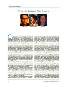
The simplest CSA3-2 is obtained by using an array of FA3's (3-bit full adders as shown in Fig. 2.1. In fact any bit adder ( B A ) cou d be used to construct a CSA. A bit adder is a unit with k input bits and e output bits, where I < k. Each input and output bit has an as-
28
....
a+b+c = u+v
Vg'o
$3
Figure 2.1: Constructing a CSA3-2 using FA3's.
3
sociated significance. If the k input bits are denoted by x l , . . . , 21. and their significances are ul, . . .,U k , and if the t output bits are denoted by y1,. . . ,ye and their significances are bl, .. . ,bl then the relation yi2b' = xj2OJ holds.
xi=,
zf=,
Coiistructing CSA networks
We are given a CSAk-t unit G that accepts its k inputs a t times 21,. , .,xk and delivers its 4 outputs a t times y1,. ,ye, where k > 4. Our task is t o compose copies of G into a network that reduces the sum of n numbers t o the sum of only e. We would like the delay of this network to be as small as possible.
..
The simplest bit adder is the 3-bit full adder FA3. The significance of the three input bits is 0 and the significances of the two outputs bits are 0 and 1 respectively. More generally, if k = 2m- 1 then an FAk which receives k input bits, and outputs m bits containing the binary representation of their sum could be constructed. The significance of all the inputs to an FAk is again 0, and the significances of the m outputs are 0 , 1 , . . ,m - 1. The fastest CSA networks which can be constructed using CSA3-2's have depths asymptotic to 3.71 log, n or 5.42 log, R , depending on whether all dyadic gates or only the AND-like gates are used (see [11],[12]). In order to get our best-performing CSA's we need to consider slightly more general BA's. If E:==, ci2' = 2m - 1 we denote by FA,, ..., the bit adder with k = T : - o c i inputs, where CO of htm : have significance 0, c1 o them will have significance 1, and so on. The unit FAcO,...,cr have m outputs with significances 0 , 1 , . . . ,m - 1. Since every number 0 5 z < 2m has a unique binary representation of length m, the output of this BA for any input vector is uniquely defined. In section 4 we describe an efficient implementation of an FA5,1. A CsA6-3 could be built using this FA:, 1 as illustrated in Fig. 2.2. The CSA's constructed in this way give rise to the shallowest known multiplication circuits. These constructions use both AND-like and exclusive-or (XOR) gates. Their asymptotic delay is about 3.57 log, n time units (excluding the time needed for the final addition). In section 5 we describe an efficient implementation of an FA7,4 using only AND-like gates. A CSA 11-4 could be built using this FA, 4 in a similar way to that shown in Fig. 2.2. The CSA's constructed in this way yield the shallowest known multiplication circuits that use only AND-like gates. Their asymptotic delay is about 4.95 log n time units (excluding again the time needed for the bnal addition).
Without loss of generality we may assume that 0 = x1 5 5 Xk and y1 5 . 5 ye. In a real 'causal' device no useful output can be given until after the first input is received, and no input can be relevant unless it precedes the final output. Hence we may assume that y1 > x1 and yt > X k .
.. .
.
..
The characteristic polynomial of G is defined to be g ( z ) = Cj=lzYJ I - C i = , z 2 * . It is easy to see that g(1) = 4 - k < 0 and g(o0) = 00. Hence the equation g z ) = 0 has at least one real root greater than l. We ca 1 the smallest such root the principal root of G and denote it by XG. The asymptotic depth of the networks we construct depends on the principal root: the larger this root, the shallower the circuit.
\
As a consequence of the causality, if all the inputs up to time t are zero, then all the outputs up to time t are zero as well. If the number of inputs still t o be given after time t is larger than the number of outputs still to be produced, then we can get a CSA unit GIt] by fixing all the inputs t o G up to time t to zero and ignoring the outputs up to that time. If for some t > 0 a unit GLt] can be obtained for which XGIII 2 XG we say that G could be improved, since we could use the smaller unit GEt]instead of G to construct circuits which are asymptotically at least as shallow. If G cannot be improved in this way then we say that it is Teduced.
For a polynomial f ( z ) = ~ ~ , f i i .we ' define f + 0 respectively f >- 0) if fi > 0 (respectively f j 2 0) or 0 5 i 5 m and also write, for example, f 5 g if (9 - f) >- 0.
I 29
0 0 0 . 0 .
Figure 2.2: Constructing a CSA6-3 using FA5,1'sFor every N > 0 we construct a CSA-network in which ct = rA/Xt + b] copies of G are based at time t for 0 5 t 5 T where X = XG, A = N / ( A h o ) , b = 1/(X - 1) and T = [log, A1 5 [logx N I . The coefficient of z t
Lemma 3.1 I f G is reduced and g ( z ) = ( z - & ) h ( z ) then h t- 0. Proof : For a polynomial f(z) = ~ ~ o f i we z define i f[tl(z) = fjzi. Note that if GLt] is a functional CSA then its characteristic polynomial is f [ ' ] ( z ) . We have h,-l = gm > 0 where m = deg(g). Suppose that for some t, 0 5 t < m - 1, we have h['+'] t- 0 but ht 5 0. Then g[t+ll(Z)
= htZt+l
+
(2
in the characteristic function, ( E T = o c t z t ) g ( z ) , of the network, gives the number of inputs or outputs required or supplied at time t . A negative number denotes inputs while a positive number denotes outputs. We claim that this network accepts at least N inputs at or after time 0, and produces only a constant number of outputs, no later than time T m 5 [log, N1 m. This follows from the next lemma.
+
+
- X G ) h [ t + l l ( z )< 0
for 1 5 z < AG. Hence AG[t+l] 2 AG, which contradicts the assumption that G is reduced. 0 We can interpret the equation A ~ h ( z ) g ( z ) = z h ( z ) as an assertion that if X ~ h di a t a items are available a t time i, for 0 5 i < m, and (some of them) are input to a copy of the unit G, then the result is that h ,. 1't ems are available at time i 1 for 0 5 i < m. This suggests that we may be able to reduce the number of items by a factor of XG at every time unit. The delay of a network for the carry save addition of n numbers in this case would be about logx,n time units.
Lemma 3.2 / T
+
+
N
+
Lo
\
z) 4 zT+l(b+ 2)h(z)
g(
.
-
Proof : T
N
+ x r A / X t + b l z t g ( z )= t=O
T
T
There is however a small obstacle to be overcome. The numbers A G ~ ,and hi are in general non-integral. We will use integers t o approximate the real numbers that we encounter and show that this does not affect the validity of our results. A copy of G that receives its inputs at times t+q,. .. ,t+ x k (and yields its outputs at times t + y l , . . . ,t + y ~ )is said to be based at time t. The essentials of a network could be described by specifying the number of CSA units that are based at each given time. The outputs produced at time t can be supplied as inputs a t time t in an arbitrary manner. If more items are consumed a t time t than produced then the network may receive some external inputs at time t. If more items are produced than consumed, then the network produces some external outputs at time t.
t= 1
4 [A/AT + b 1 z T + l h ( z ) 5 % T + l ( b + 2)h(z).
+
+
We used the fact that rB b1 e [B/X b X f B > 0. The number b was chosen to ensure t is. Or any 0 The constant number of outputs produced by these networks could be reduced to two using an additional fixed delay, independent of N .
30
h
1x 2 x 3 x 4
Y2
(a)
(b)
Y2
Figure 4.1: An implementation of an FA5,i.
4
A 6 -+ 3 Carry Save Adder
numbers will be approximately log, n N 3.57 log, n time units where X 21 1.21486 is the root of the polynomial + X~ - X 4 X3 - X2 - 4 = 0. equation
+
An implementation of an FA5,1 is given in Fig. 4.l(a). The implementation uses seven half adders (HA) and three XOR gates. A HA is composed of an XOR gate and an AND gate. The left output of an HA with inputs a,b is a b (the sum) and the right output is a A b (the carry). The three separate XOR gates used in Fig. 4.l(a) could in fact be replaced by O R gates. In order to verify the validity of this implementation we imagine at first that the three XOR gates are repla.ced by HA’s. Notice that the connections between the HA’s respect the significances of the inputs and outputs. The significance associated with each wire in the circuit is written next to that wire in Fig. 4.l(a). The inputs 3 1 , . . . ’ 2 5 have significance 0 while 2 6 has significance 1. It is easy to check that the carry output of the three HA’s that we used to replace the XOR gates are always zero so the HA’s could be replaced by XOR gates or by OR gates. Note that the input 1 5 is supplied to this unit two units of time after 21,. . .’ 2 4 are supplied and that yo is then obtained one unit of time later, even before 2 6 needs to be supplied. The outputs y1 and y2 are obtained one and two units of time after x6 is supplied. This behaviour is depicted in Fig. 4.l(b). The CSAb3 constructed using this FA5,1 will have the same delay characteristics. The results of the previous section give us the optimal way of combining these C S A h s ’ s into networks. The delay of these networks for the (carry save) addition of n
5
An 11 ---f 4 Carry Save Adder
The CSA 6-3 described in the previous section relied heavily on the use of XOR gates. An XOR gate could always be replaced by three AND-like gates with a total delay of two time units. Better results are obtained however by using a completely different design. Khrapchenko [9] gave the design of an FA, with which a CSA7+3 with the characteristics given in Fig. 5.2 could be constructed. He also described networks based on this CSA with asymptotic delay of 5.12 log n. The networks that he described were not optimal Eowever. Using the designs of section 3, or even the less general designs described in [11],[12], better networks of delay 5.07 log, n can be obtained. In this section we give an implementation of an FA7,4 using which the preceding results can be further improved. Since the design of this unit is based on Khrapchenko’s design, we give a concise summary of his construction in Fig. 5.1. In Figs. 5.1 and 5.3 we use the following notation. We denote by S A the symmetric function of k variables which takes tfie value 1 for inputs 2 1 , . .. ,zk if and only if xi E A. For example, S;567 stands for the majority function on seven variables. For conciseness we write U A for S,”(U) where U = (x1, 22,23), and VA for Sf(w) where w = (24,25,26, x,), and so on.
31
4666666 5667777 5666666 233 244 233 122 233 244 233 122
Yo
=
Y1
= =
Y2 U01
=
U02
=
U12
=
U3
= =
U03 U13 U23 U123
Vl
= = =
= =
4444 4444 4444 4444
1/13
=
2222 3333 3333 4444 3333 2222
v 4
=
v04 v34 v024 v234 v1234
=
v 2 v3
=
= = = =
Figure 5.1: Khrapchenko’s construction of an FAT.
.. ...... . .............. ............... . . .. . . . , . . . . . . s2361 . . . . . . ......... . ........,........ . . . . . . . . . . . . . . . . . . . ................. ...................
t
y1
i:
............._ ................. . . . . . .. . . . . . . FA 1 , 4 . . . . . . .................. ......
(a> Figure 5.2: The delay characteristics of Khrapchenko’s construction.
32
.
I
.
.
.
.
YO y1 Y2 U3
= = = =
s1357 s0145T13 V s2367T024 s4567T04 V 5 2 3 4 5 T l ) V ( s 0 1 2 3 T 2 V s0167T3) s234567T34 V s67T1234) V T234(s4567 V T4)
V T4
=
(u23v234
5667777 5666666 5666666
SO145
=
52367
SO167
=
52345 -
$0123
=
s4.567
5666666
s2345
=
s234567367
4555555 4555555
s234567 s67
= =
u123v1234 V (U23 u231'4 u3v34
4666666 78899996666 89999997777 78888886666 56666664444
se67
V u 1 2 3 v 3 4 ) V ((u3vl.234 V v 4 ) V T4)
v
Figure 5.3: The new
FA7,4
V v234)
construction.
Ts4567 T4
Figure 5.4: The final stages in the computation of
+
x2 x1
.-. x7 +.
-U.........
x2 x1
se567
.-. x7
+
x2
i
x1
...
......... ......... ............. ............. ..,,,,s . . . . . . . . . . . .S6, .... .................... . . . . . . . . . . . . . . .T .3.4. . . . . . . . . . . . . . . T ,. ~ ~ ~ . . . . s4567 vT4 . . . . . . ....................
Figure 5.5: The final stages in the computation of
33
y3.
x2
... ‘ 1
x2
i’? ........ .........
...
... x 1
........
.......... ........... . . . . . . . . . . . . . ........... ................... ........... ................... .................... ................... YO ...................
x2
-
.........
1
........... .................
................ ................. ................. ................. ................. ................ . . . . . . . . . . . . . . . . . ................. ................. .................
... X I
2 3
FA,,,
4
5 6
7
-
I
....
................. ............
............ yo ........
y3
y1
Yl
y2
Y2
(b)
Figure 5.6: The delay characteristics of the new FA7,4. [4] Boppana R., Sipser M., “The complexity of finite functions,” in Handbook of Theoretical Computer Science Vol. A : Algorithms and Complezity, ed. van Leeuwen, Elsevier/MIT Press, 1990, pp. 757-804.
The numbers given to the left of each formula in Fig. 5.1 are the depths of the variables in that formula. They will be called delay vectors. The delay characteristics of the three output bits yo,y1,yz that compose Khrapchenko’s FA7 are described in Fig. 5.2(a. In [12] it is shown that the optimal way of com ining these three units into a single unit is as presented in Fig. 5.2(b). The construction of our new FA7,4 is given in Fig. 5.3. Figures 5.4 and 5.5 depict the final stages in the construction of y3. The delay characteristics of yo, y ~y2, , y3 are shown in Fig. 5.6(a) and we see that we can fit them all into the unit outlined in Fig. 5.6(b). By the results of section 3, we can combine the new CSA 11-4’s into networks of asymptotic depth logx n = 4.95 log2 n where X 11 1.15041 is the principal root of the equation 2X9 X8 X6 - 4X2 - A - 6 = 0.
2
[5] Dadda L., “Some schemes for parallel multipliers,” Alta Frequenza, Vol. 34 (1965), pp. 343-356. [6] Dunne P.E., The complezity of Boolean networks, Academic Press, 1988. [7] Karatsuba A., Ofman Y., “Multiplication of multidigit numbers on automata,” Soviet Physics Dokl., Vol. 7 (1963), pp. 595-596. [8] Khrapchenko V.M., “Asymptotic estimation of addition time of a parallel adder,” Problemy Kibernet., Vol. 19 (1967), pp. 107-122 (in Russian). English translation in Syst. Theory Res., Vol. 19 (1970), pp. 105-122.
+ +
6
Concluding remarks
[9] Khrapchenko V.M., “Some bounds for the time of multiplication,” Problemy Kibernet., Vol. 33 (1978), pp. 221-227 (in Russian).
We have presented a general construction and some specific designs which yield circuits for carry save addition which are faster than those previously published. Although we have only given asymptotic results here, the same methods provide efficient networks for small nunibers of inputs. There is a polynomial time algorithm which, for any CSA G and any n, gives an optimaldepth network of G’s for the carry save addition of n inputs. Our constants will no doubt be improved before long, but the techniques provide a simple construction method which may be of more durable value.
Ofman Y., “On the algorithmic complexity of discrete functions,” Doklady Akademii Nauk SSSR, 145 pp. 48-51 (in Russian). English translation in Sov. Phys. Doklady, Vol. 7 (1963) pp. 589-591. Paterson M.S., Pippenger N., Zwick U., “Faster circuits and shorter formulae for multiple addition, multiplication and symmetric Boolean functions,” Proceedings of the 31st Ann. IEEE Symp. on Found. of Comp. Sci., St. Louis 1990.
References
Paterson M.S., Pippeiiger N., Zwick U., “Optimal carry save networks,” Boolean function complezity: Selected papers from the LMS symposium, Durham 1990. To appear, Cambridge Univ. Press, 1991.
El Gama1 A., Gluss D., Ang P-€I., Greene J., Reyneri J., “A CMOS 32 bit Wallace tree multiplier-accumulator,” 1986 ISSCC Digest of Technical Papers, pp. 194-195.
Wallace C.S., “A suggestion for a fast multiplier,” IEEE Trans. Electronic Comp. EC-13 (1964) pp. 14-17.
Avizienis A., “Signed-digit number representation for fast parallel arithmetic,” IEEE Trans. Elec. Comp. Vol. EClO (1961), pp. 389-400.
Wegener I., The com,plexity of Boolean functions, Wiley-Teubner Series in Computer Science, 1987.
Brent R., “On the addition of binary numbers,” IEEE Trans. on Comp., C-19 (1970), pp. 758-759.
34


![Chaos in circuits and systems [Book Review] - Circuits ... - IEEE Xplore](https://m.moam.info/img/260x300/chaos-in-circuits-and-systems-book-review-circuits_5c57ebfc097c479a6e8b45a0.jpg)