Mar 15, 2006 - movements of the Shockley partial dislocations on heating the material above the Af ..... Trans., JIM 34 (1993) 1169â1176. 5) L. Jian and C. M. ...
Materials Transactions, Vol. 47, No. 3 (2006) pp. 564 to 570 Special Issue on Shape Memory Alloys and Their Applications #2006 The Japan Institute of Metals
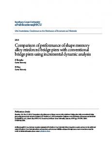
Elastic Energy Analysis of Carbide and Nitride-Type Precipitates in an Fe–Mn–Si–Cr Shape Memory Alloy Susan Farjami1 and Hiroshi Kubo2 1 2
Department of Materials Science, Graduate School of Engineering, Tohoku University, Sendai 980-8579, Japan Kanto Polytechnic University, 612-1 Mitake Yokokura, Oyama 323-0810, Japan
The application of the microscopic theory of elasticity in a discrete lattice model is made on the transitional metal carbide and nitride precipitates formed in the Fe–Mn–Si–Cr shape memory alloy in conjunction with the improvement of shape memory effect (strain) and the improvement of strength. Two distinguishable methods of analysis have been established using the microscopic theory of elasticity in a discrete lattice model: One is the establishment of the description of precipitate and misfit dislocations in Fourier space. The second is the rigorous estimation of interaction energies among precipitate and misfit dislocations. The results could successfully describe the shape of the precipitate observed in the experimental investigation. It was also concluded that the elastic strain energy increases with the lattice parameter of the precipitate. Among the transition carbides and nitrides under investigations, VN, which revealed the minimum value of the elastic energy, is manifested to be the most favored one for the precipitation enhanced Fe–Mn–Si–Cr shape memory alloy. Homogeneously precipitated VN containing materials could show large deformability, higher strength by precipitation hardening and the higher shape recovery strain due to the nucleation sites of the precipitates in its reverse phase transformation. (Received September 27, 2005; Accepted November 7, 2005; Published March 15, 2006) Keywords: shape memory alloy (SMA), precipitate, elastic energy, microscopic theory of elasticity
1.
Introduction
Following the early reports of Sato et al.1,2) on the shape memory effect (SME) in an Fe–Mn–Si based alloy, many investigations have been performed on the SME and its enhancement by variety of methods.3–11) The origin of the SME in this alloy is the reversion of the stress-induced "martensite phase to the parent �-austenite that occurs by the movements of the Shockley partial dislocations on heating the material above the Af temperature.1,2,12) Among the proposed methods of improving the SME of Fe–Mn–Si based shape memory alloys, precipitation hardening seems to be a suitable one to the industrial applications without the necessity of performing repeated thermal cycles and deformation.8–10) Depending on the temperature and duration of the heat treatment, precipitates might have different morphologies reportedly changing from a plate and cube shaped morphology at the early stage of aging to an octahedron and tetrakaidecahedron on further aging.13–15) In order to maintain the lattice continuity in a coherent or semicoherent microstructue, the lattice mismatch between the precipitate and the matrix phase is accommodated by elastic displacements of atoms from their equilibrium lattice positions. Therefore, formation of such precipitates generates elastic strain energy whose magnitude depends on the degree of lattice mismatch, the elastic properties of each phase, and their shapes and spatial distributions.16–18) It is apparent from the thermodynamic point of view that minimizing this energy governs the precipitate morphology predicting either the final equilibrium shape or a few particular intermediate shapes that were suggested by experimental observations. The morphologies of the precipitates could be interpreted from the static elastic energy point of view using microscopic theory of elasticity, which has been described either by Fourier transformed method in reciprocal space16,19–22) or in real space,18,23,24) particularly using Eshelby tensors.25–29) In an earlier theoretical analysis by the present authors, the morphological evolution of VN precipitates was studied in an
Fe–28Mn–6Si–5Cr (mass%) alloy based on the Fourier transformed microscopic theory of elasticity.15) To compare the calculated elastic energy of VN precipitates with other precipitate compounds, the application of the established equations is expanded in the present work to the estimation of elastic energies of several other carbide and nitride-type precipitates. Our objective is to provide a database on the elastic energy of a series of transitional metal carbide and nitrides that are mostly utilized in precipitation hardening process. For this, the theoretical analysis of the shape of the precipitates will be made on the basis of the Fourier transformed microscopic theory of elasticity, where the interaction force field between the misfit dislocations and also between the precipitate-misfit dislocations are incorporated in the analytical expression of the elastic strain energy. 2.
Formulation of Elastic Strain Energy in Fourier Space
2.1
Elastic strain energy of precipitate surrounded by misfit dislocations Based on Khachaturyan’s16) theoretical analysis of isostructural cubic to cubic phase transformation, the elastic strain energy E of the different multiple (p) kinds of defects coexisting in the matrix phase can be described in reciprocal space (Fourier space) as follows,30) E ¼ Eself þ Einteraction ; Eself ¼
ð1Þ
2 N XX Y p p ðqÞ� p ðqÞ� p � ðqÞ; 2 q p¼1
Einteraction ¼
ð2Þ
2 X 2 N XX 0 0 Y p p ðqÞ� p ðqÞ� p � ðqÞ; 2 q p¼1 p0 ¼1
ðp 6¼ p0 Þ
ð3Þ
where the precipitate and misfit dislocation are distinguished by the symbol p ¼ 0 and p ¼ 1, respectively. Eself is the
Elastic Energy Analysis of Carbide and Nitride-Type Precipitates in an Fe–Mn–Si–Cr Shape Memory Alloy
elastic self energy of each defect (precipitate or misfit dislocation) and Einteraction represents the elastic interaction energy between the precipitate (p ¼ 1) and misfit dislocation (p0 ¼ 1) defect. The symbol � p ðqÞ, so-called the defect amplitude in the microscopic theory of elasticity, is the Fourier transform of the p-th defect. The product form of the 0 defect amplitude � p ðqÞ� p � ðqÞ is the Laue interference function in the diffraction theory that represents shape function of the precipitate. The wave vector (q) that is a short hand notation for (qx ; qy ; qz ), represents the allowed reciprocal vector in the first Brillouin zone. The function 0 Y p p ðqÞ is called an elastic energy modulus (EEM henceforth) of p–p0 defect pair, which is represented by the elastic constants �ijkl of the crystal and the geometry of the crystal lattice rearrangements as, 0
Y p p ðqÞ ¼
0 �ijkl �ijp �klp
�
p0 ni �ijp �jl ðnÞ�lm nm ;
565
Table 1 Lattice parameter,31Þ amount of misfit with austenite (a� ¼ 0:358 nm), and each layer of introducing the misfit dislocation for different carbide and nitride-type precipitates. Lattice Parameter (nm)
Amount of misfit (%)
Each layer of introducing the Misfit Dislocation
VN
0.4110
14.8
8
VC
0.4182
16.8
7
TiN TiC
0.4246 0.4329
18.6 20.9
6 6
NbN
0.4388
22.6
5
TaC
0.4456
24.5
5
NbC
0.4470
24.9
5
ZrN
0.4570
27.6
5
HfC
0.4641
29.6
4
ZrC
0.4695
31.1
4
Precipitate
ð4Þ
where the tensor �ijp represents the stress-free strain of the precipitate (p ¼ 0) and the misfit dislocation (p ¼ 1). The symbol (n) is the normalized vector of (q) and the tensor �ijp is the stress free stress that is given by �ijkl �klp . The tensor �jl ðnÞ that represents the Green function of elastic strain in the crystal could be explicitly expressed in terms of the elastic constants �ijkl and a normalized wave vector (ni ).16,23,30) The first term in eq. (4) multiplied by the amplitude product 0 � p ðqÞ� p � ðqÞ is called the initial energy of strain, which represents the strain energy induced by the stress-free strain. The second term represents the relaxation term of the elastic strain energy that is originated from the balance of lattice force fields. Three variants of misfit dislocation loops were supposed to be formed regularly during the growth of the precipitate with a constant separation distance in the three different directions of crystal axes. The forms of the EEM of the precipitate (p ¼ 0 and p0 ¼ 0), the misfit dislocation (p ¼ 1 and p0 ¼ 1), and the interaction term between the precipitate (p ¼ 0) and misfit dislocation (p0 ¼ 1) are given in detail in Ref. 15). In case of the cubic to cubic phase transformation, the tensor �ijp¼0 equals ��ij , �ij being the delta function. The stress-free transformation strain � p¼0 of the precipitate is then given by, a p � a� � p¼0 ¼ ; ð5Þ a� in which a� and a p represent the lattice parameters of the austenite and precipitate, respectively. In case of misfit dislocations (p ¼ 1), we distinguish the different variant of misfit dislocation loops by the defect amplitude � p¼1 ðd; qÞ with the direction d ¼ x, y, or z normal to the loop. The numerical value on the lattice parameter31) of different types of carbide and nitride precipitates utilized in this study, together with their amount of the misfit with the surrounding austenite, and also number of each layer at which the misfit dislocation is frequently introduced are all presented in Table 1. The final form of the elastic self-energy is given by the summation of each self-energy of the precipitate and misfit dislocation as, N X 00 Eself ¼ ½Y ðqÞf� p¼0 ðqÞg2 2 q
þ 3Y 11 ðz; z; qÞf� p¼1 ðz; qÞg2 g�: The interaction energy is described as follows, N X 01 Einteraction ¼ 6Y ðz; z; qÞ� p¼0 ðqÞ� p¼1 ðz; qÞ: 2 q
ð6Þ
ð7Þ
The resultant elastic energy of the precipitate surrounded by misfit dislocations is then given by, N X 00 Epþm ¼ ½Y ðqÞ� p¼0 ðqÞ� p¼0� ðqÞ 2 q þ 3Y 11 ðz; z; qÞf� p¼1 ðz; qÞg2 þ 6Y 11 ðx; z; qÞf� p¼1 ðx; qÞ� p¼1� ðz; qÞg þ 6Y 01 ðx; z; qÞf� p¼0 ðqÞ� p¼1 ðz; qÞg�:
ð8Þ
2.2 Fourier transformation of octahedron precipitate For a simple analytical expression of the Fourier transform (FT) of the octahedron precipitate, the axes �[100], �[010] and �[001] were defined as the normal to the edge of the basal plane of the octahedron precipitate by =4 rotation around the z[001] axis as shown in Fig. 1(a). Figure 1(b) represents the cross section normal to (a), which exhibits the height in the � direction. Corresponding to the (�; �; �) basis, the reciprocal lattice vectors are defined as ( � ; � ; � ). The Fourier transformation of the octahedron is done by starting from the �–� plane located at n� position in the �direction, where n� is the number of atom planes measured in the �-axis direction. The FT of the octahedron precipitate then can be completed by the FT of the former function in the �-direction. It was supposed that 2N� þ 1 atoms are measured along AB in the �-direction and 2N� þ 1 atom layers along OT in the �-direction of Fig. 1(b). According to the definition of the axes � and � in Fig. 1(a), we have N�O ¼ N�O , where the upper suffix O is attached specifically to identify the designation of variables belonging to the octahedron precipitate. The total number of atoms Natom in the octahedron precipitate is to be fixed in the calculation of elastic strain energy. The final form of the FT of the lattice system in the octahedron precipitate is expressed as follows,15)
566
S. Farjami and H. Kubo
β[010]
γ [001] // Z[001]crystal
Y[010]crystal
T [111]crystal 21/2a b
α[100] 2a A
B
α[100] A
O
B
2a
X[100]crystal
(a)
T'
(b)
Fig. 1 Axis arrangements of octahedron (a) in the basal plane by =4 rotation around the axis x½001� ¼ �½001� of the crystal. (b) Octahedron viewed from ½11� 0�.
�ðqÞ ¼
1 1 ½2 � 2 cosð � n� Þ� ½2 � 2 cosð � n� Þ� � ½Lðs� ÞLðs� ÞfQð� � þÞ þ Qð� � �Þ þ 1g þ Lð�s� ÞLð�s� ÞfQðþ þ þÞ þ Qðþ þ �Þ þ 1g þ Lðs� ÞLð�s� ÞfQð� þ þÞ þ Qð� þ �Þ þ 1g þ Lð�s� ÞLðs� ÞfQðþ � þÞ þ Qðþ � �Þ þ 1g�;
ð9Þ
where the parameters Lðs� Þ and Qð� � þÞ etc are defined as, Lðs� Þ ¼ ½1 � expðis� n� Þ� exp½is� N� �: Qð� � þÞ ¼
exp½iPð� � þÞn� � � 1 � exp½iPð� � þÞðN� þ n� Þ� þ exp½iPð� � þÞN� � : 2 � 2 cos½Pð� � þÞn� �
Pð� � þÞ ¼ �s� N� =N� � s� N� =N� þ s� :
ð10Þ ð11Þ ð12Þ
Because the reciprocal wave vector should be defined by the common unit, i.e., (2=a), we have recounted the number of allowed reciprocal points in the �[100] and �[010] direction. Consequently, the allowed reciprocal points in the first Brillouin zone is defined as, pffiffiffi si ¼ �2 2 i ; ði ¼ �; �Þ: ð13Þ s� ¼ �2 � : ð14Þ In the eq. (9), ni (i ¼ �; �; �) is equal to unity for the lattice system of the octahedron precipitate. 2.3 Fourier transformation of misfit dislocation The Fourier transformation of misfit dislocation loops, � p¼1 ð�; qÞ, is obtained in a similar form of eq. (9). For introducing �-variant misfit dislocation loops, the vacant planes are supposed to be located at every N�1 planes in the �-direction. They are arranged in sequence as (N�1 ; N�2 ; N�3 . . . ; N�l ; . . . ; N�L ), where the variable N�l indicates the numerical values lN�1 and N�L indicates the maximum value of N�l . Therefore, � p¼1 ð�; qÞ is obtained by replacing the symbol n� and N� in eq. (9) with the symbol N�1 and NiL , respectively. 2.4
Fourier transformation of Cube shape of precipitate with facial planes parallel to f100gxyz At the early stage of aging, precipitates are formed in a cube shape with the facial planes parallel to f100gxyz . The lattice system of a cubic precipitate that has 2Ni þ 1 atom planes along each Cartesian axis in the i ¼ �, � or � direction can be Fourier transformed as follows, �ðqÞ ¼
cos½s� N� � � cos½s� ðN� þ n� Þ� cos½s� N� � � cos½s� ðN� þ n� Þ� 1 � cos½s� n� � 1 � cos½s� n� � �
cos½s� N� � � cos½s� ðN� þ n� Þ� : 1 � cos½s� n� �
ð15Þ
Elastic Energy Analysis of Carbide and Nitride-Type Precipitates in an Fe–Mn–Si–Cr Shape Memory Alloy 0.02
0.02
0.01
0.01
0
0
–0.01
–0.01
–0.02 –0.02
–0.01
0
0.01
8.3305E14
–0.02 –0.02
0.02
9.2264E20
–0.01
0
8.5395E16
0.02
8.2446E20
(a) Fig. 2
0.01
567
(b)
Contour plots of the elastic energy of NbC precipitates for (a) an octahedron shape, (b) a cube shape with {100} interfacial planes.
8.00E-21
Octahedron {100}-interface Cube
Precipitate Self Elastic Energy (J/atom)
7.00E-21 6.00E-21 5.00E-21 4.00E-21 3.00E-21 2.00E-21 1.00E-21 0.00E+00
VN
VC
TiN
TiC
NbN
TaC
NbC
ZrN
HfC
ZrC
Fig. 3 Elastic self energy of precipitates with different shapes and compositions.
In order to obtain the exact number of total atoms in the precipitate in eq. (15) by setting s� ! 0, s� ! 0 and s� ! 0, we have to adjust the allowed number of reciprocal points. Normalizing the unit in the x-direction in Fourier space as 1=a and the unit in y- and z-direction as 2=a, the allowed reciprocal points, i.e., s� , s� and s� in eq. (15) should be replaced as, s� ¼ �4 qx : ð16Þ si ¼ �2 qj ; 3.
ði ¼ �; j ¼ yÞ; ði ¼ �; j ¼ zÞ
ð17Þ
Calculated Results of Elastic Strain Energy Using eqs. (9) and (15), the defect amplitude � p ðqÞ of the
lattice system in two different shapes of various carbide and nitride precipitates were estimated. The EEM of �-Fe was calculated using the inter-atomic force constants obtained by Zarestky and Stassis.32) Figure 2 indicates the elastic strain energy E of octahedron shape and cube shape of NbC precipitates as an example. It is the case of extremely long wavelengths of phase transition, i.e., kðqÞ � 0 to be examined in an area close to the origin of the reciprocal space. By summing up the elastic energy 0 0 Y p p ðqÞ� p ðqÞ� p � ðqÞ at each kðqÞ point in the reciprocal space, the numerical value for the elastic strain energy of each shape could be obtained. The calculated results of elastic strain energy of the octahedron and the cube shape of carbide and nitride precipitates are plotted in Fig. 3 where the
568
S. Farjami and H. Kubo 0.02
0.02
0.01
0.01
0
0
–0.01
–0.01
–0.02 –0.02
–0.01
0
0.01
7.4722E14
–0.02 –0.02
0.02
8.151E20
–0.01
0
7.2127E16
0.01
0.02
7.1763E20
(a)
(b)
Fig. 4 Contour plots of the elastic energy of NbC precipitates for (a) an octahedron shape, (b) a cube shape with {100} interfacial planes surrounded by misfit dislocations.
5.00E-21
Octahedron {100}-interface Cube
Precipitate+Misfit Elastic Energy (J/atom)
4.50E-21 4.00E-21 3.50E-21 3.00E-21 2.50E-21 2.00E-21 1.50E-21 1.00E-21 5.00E-22 0.00E+00 Fig. 5
VN
VC
TiN
TiC
NbN
TaC
NbC
ZrN
HfC
ZrC
Total elastic energy of precipitates surrounded by misfit dislocations for different compositions.
precipitates are arranged according to their lattice parameter (see Table 1) in the horizontal axis of the graph. Since the elastic interaction energy of the misfit dislocations and also precipitate-misfit dislocations are yet not introduced in the estimation of the total elastic energy, the ones presented in Fig. 3 are just distinguished as self elastic energy. It is obvious from this figure that as long as the self energy of the precipitate is solely concerned, the self elastic strain energy of the octahedron shape of precipitates indicate a larger value than that of the cube shape of precipitates surrounded by {100} interfacial planes. This dependency of the elastic strain energy value on the shape of the precipitate is consistent with the results of Onaka et al.,25–28) who have estimated the
elastic strain energy using the continuum model in real space. It is therefore conjectured that the interaction energy of the misfit dislocations surrounding the precipitate may work to reduce the total elastic energy of the octahedron precipitate more than that of the cube shape. Figure 4 shows the contour plots of the elastic energy of (a) octahedron and (b) cube with {100} interfacial planes surrounded by misfit dislocations for the NbC precipitate. By using the FT method in the microscopic theory of elasticity, the interaction terms can be incorporated in the analytical equation of elastic strain energy. Due to the amount of the misfit with the austenite, it was assumed that the misfit dislocations are introduced at every 8 layers for VN compounds, every 7 layers for VC,
Elastic Energy Analysis of Carbide and Nitride-Type Precipitates in an Fe–Mn–Si–Cr Shape Memory Alloy
every 6 layers for TiN and TiC, every 5 layers for NbN, NbC, TaC and ZrN, and finally every 4 layers for HfC and ZrC in the three orthogonal directions, i.e., x-, y- and z-direction, respectively. The numerical value of elastic strain energies of the different types of the precipitates surrounded by misfit dislocations are shown as total energy in Fig. 5. They are estimated by summing up the self elastic energies of the precipitates and the misfit dislocation and also their interaction energies. The results indicate the minimum value of the elastic strain energy for the octahedron precipitate. This decrease of the elastic strain energy is supposedly originated from the interaction force field between misfit dislocations. It is also clear from the figure that the VN octahedral precipitates are preferred for their lowest total elastic energy amongst all the estimated results of different precipitates. It is, indeed, the advantage of using VN over the other precipitate compounds that have been previously used to obtain a homogeneously distributed coherent precipitates and enhance the strength and shape memory effect of the Fe–Mn– Si based alloys. 4.
Discussion
It was pointed out earlier that the morphology of coherent precipitates is strongly influenced by the elastic energy associated with the misfit between the precipitate and the matrix structure. The precipitate shape dependence on the elastic strain energy is thus important in understanding shape changes during the growth and coarsening of precipitates. At the early stage of precipitation, however, small cube shape precipitates with the size of several nanometers in edge width7,15,33) are formed without misfit dislocations. At this stage of formation of coherent precipitates, because of the minimum interfacial energy of {100} interfacial planes34) and the minimum elastic strain energy of the cube,27) the precipitates are formed in a cube shape with {100} interfaces. As aging proceeds, the precipitates increase in size and elastic strain energy plays an increasingly important role in setting the morphology of the precipitate. Being volume dependent, the elastic energy dominates over the interfacial energy at later stages of coarsening when the surface to volume ratio decreases. The large lattice mismatch between the precipitate and the matrix phase irreducibly introduce misfit dislocations at the precipitation interface. In order to estimate the coherent strain energy, the elastic strain energy of the precipitates and also the interaction term between misfit dislocations and between the misfit dislocation-precipitate were incorporated using the microscopic theory of elasticity. As a result, the minimum coherent strain energy of the octahedron shape of the precipitate was successfully explained in comparison to the cube shape with {100} interfacial planes. In case of the octahedron precipitate, more than twice of the number of misfit dislocations are introduced, even in one direction, in comparison to those of the cube shaped precipitate. As a result, more significant relaxation of the strain is expected to take place in the octahedron precipitate. On the other hand, the {100} planes of the parent austenite are likely the most favorable nucleation sites for the precipitation of the small cube-like precipitate compounds at the beginning of the
569
precipitation procedure. In addition, our result of the total elastic energy estimation revealed the minimum value of the elastic energy for the VN precipitate. In fact, an increasing trend of the elastic energy was observed in connection to the size of the lattice parameter of the precipitates. Having the smallest value of the lattice parameter, VN appears to be the most favored precipitate, at least from the viewpoint of the mechanical strengthening, for the precipitation hardening process of the Fe–Mn–Si–Cr shape memory alloy. 5.
Summary
The equilibrium shape of various transitional metal carbide and nitride precipitates were theoretically analyzed by utilizing the Fourier transformed microscopic elasticity method. As a result, the elastic energy of the precipitate, misfit dislocations, and the interaction elastic energy of the precipitates and misfit dislocations were calculated. At an early stage of aging, the precipitates have a cube shape with the {100} habit planes due to the smallest chemical energy of {100} interface. On the other hand, on prolonged aging, the analysis of the bulk elastic energy using the microscopic theory of elasticity revealed that the octahedron shape of the precipitates have a lower elastic energy compared to the cube shape of the precipitate with {100} interfacial planes. This result of the theoretical analysis indicates that the precipitates are formed in the octahedral shape with a lower strain energy compared to the cube-shaped particle containing the same total numbers of unit cells. It was concluded that the misfit dislocations surrounding the octahedral precipitate might reduce the total elastic energy of the octahedron precipitate more than that of the cubic one. The results could successfully describe the shape of the precipitates observed in the experimental investigations. REFERENCES 1) A. Sato, E. Chishima, K. Soma and T. Mori: Acta Metall. 30 (1982) 1177–1183. 2) A. Sato, E. Chishima, Y. Yamaji and T. Mori: Acta Metall. 32 (1984) 539–547. 3) H. Otsuka, M. Murakami and S. Matsuda: Proc. MRS Int. Meetings on Advanced Materials, ed. by M. Doyama et al., Shape Memory Materials, MRS 9 (1989) p. 451. 4) K. Ogawa and S. Kajiwara: Mater. Trans., JIM 34 (1993) 1169–1176. 5) L. Jian and C. M. Wayman: Mater. Characterization 32 (1994) 215– 226. 6) K. Tsuzaki, Y. Natsume, Y. Tomota and T. Maki: Scr. Metall. Mater. 33 (1995) 1087–1092. 7) A. Baruj, T. Kikuchi, S. Kajiwara and N. Shinya: Mater. Trans., JIM. 43 (2002) 585–588. 8) S. Kajiwara, D. Liu, T. Kikuchi and N. Shinya: Scr. Mater. 44 (2001) 2809–2814. 9) A. Ariapour, I. Yakubtsov and D. D. Perovic: Metall. Mater. Trans. A 32 (2001) 1621–1628. 10) H. Kubo, K. Nakamura, S. Farjami and T. Maruyama: Mater. Sci. Eng. A 378 (2004) 343–348. 11) N. Yoneyama, T. Setoda, S. Kumai, A. Sato, M. Komatsu and M. Kiritani: Mater. Sci. Eng. A 350 (2003) 125–132. 12) H. Otsuka, H. Yamada, T. Maruyama, H. Tanahashi, S. Matsuda and M. Murakami: ISIJ Int. 30 (1990) 674–679. 13) Y. Yazawa, T. Furuhara and T. Maki: Acta Mater. 52 (2004) 3727– 3736.
570
S. Farjami and H. Kubo
14) S. Farjami, K. Hiraga and H. Kubo: Mater. Trans. 45 (2004) 930–935. 15) S. Farjami, K. Hiraga and H. Kubo: Acta Mater. 53 (2005) 419–431. 16) A. G. Khachaturyan: Theory of Structural Transformation in Solids, (Wiley, New York, 1983), p. 293. 17) J. D. Eshelby: Progress in Solid Mechanics, vol. II, ed. by I. N. Sneddon and R. Hill, (North Holland, Amsterdam, 1961), p. 87. 18) T. Mura: Micromechanics of Defects in Solids, 2nd rev. ed., (Martinus Nijhoff Pub., Dordrecht, 1987), p. 74. 19) H. E. Cook and D. de Fontaine: Acta Matall. 17 (1969) 915–924. 20) H. E. Cook and D. de Fontaine: Acta Matall. 19 (1971) 607–616. 21) A. G. Khachaturyan, S. Semenovskaya and J. M. Morris: Acta Metall. 36 (1988) 1563–1572. 22) Y. Wang and A. G. Khachaturyan: Acta Metall. Mater. 43 (1995) 1837–1857. 23) T. Mura, T. Mori and M. Kato: J. Mech. Phys. Solids 24 (1976) 305– 318.
24) T. Mori, P. C. Cheng, M. Kato and T. Mura: Acta Metall. 26 (1978) 1435–1441. 25) J. K. Lee and W. C. Johnson: Acta Metall. 26 (1978) 541–545. 26) S. Onaka, T. Fujii and M. Kato: Mech. Mater. 20 (1995) 329–336. 27) M. Kato, T. Fujii and S. Onaka: Mater. Sci. Eng. A 211 (1996) 95–103. 28) S. Onaka, N. Kobayashi, T. Fujii and M. Kato: Mater. Sci. Eng. A 347 (2003) 42–49. 29) S. Onaka, T. Fujii and M. Kato: Mech. Mater. 37 (2005) 179–187. 30) H. E. Cook: Acta Metall. 23 (1975) 1027–1039. 31) W. B. Pearson: A handbook of lattice spacings and structures of metals and alloys, (Pergamon, London, 1967). 32) J. Zarestky and C. Stassis: Phys. Rev. B 35 (1986) 4500–4502. 33) F. G. Wei, T. Hara and K. Tsuzaki: Philos. Mag. 84 (2004) 1735–1751. 34) Z. G. Yang and M. Enomoto: Metall. Mater. Trans. A 32 (2001) 267– 274.