Available online at www.sciencedirect.com
Procedia Engineering 47 (2012) 742 – 745
Proc. Eurosensors XXVI, September 9-12, 2012, Kraków, Poland
SiGe MEMS Accelerometers Combining a Large Bandwidth with a High Capacitive Sensitivity A. Ray Chaudhuria,b,*, S. Severia, M. A. Erismisa, L. A. Francisb and A. Witvrouwa a
b
Imec, Kapeldreef 75, 3001 Leuven, Belgium ICTEAM Institute, Université catholique de Louvain, Place du Levant 3, 1348 Louvain-la-Neuve, Belgium
Abstract This paper evaluates the performance characteristics of a new miniaturized lateral capacitive accelerometer with a high bandwidth as well as a high sensitivity, utilizing a low thermal budget SiGe MEMS technology. The accelerometer combines a 4 μm SiGe structural layer thickness with a small capacitive sensing gap of 500 nm, leading to an improvement in sensitivity along with large bandwidth and a reduction in overall dimension compared to conventional accelerometers, which have gaps in the order of 1 μm. The accelerometer studied here is targeted for a maximum operational range of ±2g. © 2012 The Authors. Published by Elsevier Ltd. Selection and/or peer-review under responsibility of the Symposium Cracoviense © 2012 Published by CC Elsevier Ltd. Sp. z.o.o. Open access under BY-NC-ND license.
Keywords: Accelerometer,Bandwidth,Sensitivity,SiGe MEMS technology
1. Introduction Since the 90’s MEMS accelerometers have been used for automotive applications, e.g., crash sensor for airbags. Recently accelerometers are also finding rapidly their way into consumer products such as game controllers, smartphones, tablet PCs, etc. Consumer applications require low cost, compact and low-power sensors. These requirements can be met by making the sensor small and preferably monolithically integrated with its driving electronics. This paper evaluates the performance characteristics of a miniaturized lateral capacitive accelerometer, utilizing a low thermal budget, CMOS compatible, SiGe MEMS technology. Miniaturization is expected to lead to a lower sensitivity due to the decrease in mass. The decrease in mass will in addition lead to an increase in resonance frequency. While an increase in resonance frequency degrades the sensor sensitivity [1], the bandwidth of the MEMS sensor increases with increasing resonance frequency. Designing a structure with a high bandwidth as well as a high sensitivity is thus challenging * Ashesh Ray Chaudhuri. Tel.: +32 16 28 19 63. E-mail address:
[email protected].
1877-7058 © 2012 The Authors. Published by Elsevier Ltd. Selection and/or peer-review under responsibility of the Symposium Cracoviense Sp. z.o.o. Open access under CC BY-NC-ND license. doi:10.1016/j.proeng.2012.09.254
A. Ray Chaudhuri et al. / Procedia Engineering 47 (2012) 742 – 745
For the capacitive accelerometer presented in this work, this trade-off was overcome by developing small capacitive sensing gaps. The accelerometer studied features a 4 μm thick SiGe structural layer with a capacitive sensing gap of 500 nm, leading to an improvement in sensitivity and a reduction in overall dimension as compared to conventional accelerometers, which have gaps in the order of 1 μm [2]. Different performance parameters like the capacitive sensitivity, the resonance frequency and the bandwidth of the accelerometer have been analyzed through analytical and finite element method (FEM) based modeling. The accelerometer device studied here is targeted for consumer applications which require a maximum operational range of ±2g. 2. Design of the sensor structure The sensor element is a variable gap type differential capacitor whose output is proportional to the applied acceleration. Basically it consists of a proof mass with interdigitated combs, i.e., a movable comb in between two fixed combs, and folded ‘U’ springs supporting the proof mass at its corners (Figure 1). Because of the differential capacitor design, the capacitance on one side of the interdigitated comb structure increases (C2=C0+ΔC) due to a displacement xo of the movable comb with acceleration, while the capacitance on the other side decreases (C1=C0-ΔC). Assuming a small value of the displacement xo, the differential capacitance Cdiff can be calculated as follows: (1) Cdiff = C2 - C1= (2εAxo)/do2 where ε is the permittivity of the surrounding medium, do is the initial gap between the fingers and A is the overlapping area between the fixed outer fingers and the moving finger. We need as large a differential capacitance Cdiff as feasible in order to increase the resolution. However longer fingers are not desirable for several reasons including their susceptibility for both as–processed and in-use stiction. From Equation (1) it is also clear that the gap spacing has a much more pronounced effect on Cdiff as compared to the area A which is proportional to the finger length. This is the reason why in this work we focus on designing accelerometers with a small sensing gap. The displacement and the capacitive sensitivity along the sensing axis are designed to be high, while at the same time a high natural frequency is maintained for a larger bandwidth. The chosen critical dimensions of the accelerometer structure are given in Table I.
Fig. 1. (a)3D model of the structure; (b) Fabricated U-spring and comb assembly
3. Behavioral Modeling 3.1 Capacitive sensitivity The displacement of the accelerometer xo in response to a change in acceleration ∆g is expressed as (m/k)*∆g with m the mass of the accelerometer and k the mechanical spring constant of the beam. For the springs used here, k can be evaluated from k=4Ehw3/(L13+L23) [2] where E is Young’s modulus of the
743
744
A. Ray Chaudhuri et al. / Procedia Engineering 47 (2012) 742 – 745
Table 1: Structure dimensions
Proof Mass Dimensions
Comb structure Dimensions
Spring flexure Dimensions
Parameter
Value
Area of proof mass
300*100 μm2
Area of etch holes
1*1 μm2
Pitch between two etch holes
3 μm
No. of Comb cells
54
Length and width of each comb
105 and 1 μm
Area of overlap A
90 μm *4 μm
No of U-Springs
4
Width of U-Springs w
1.8μm
Length of U-Springs (L1 and L2)
110 and 80 μm
Distance between beams of each U- Springs
1.2μm
SiGe, assumed to be 120 GPa, h is the thickness of the structural layer and w is the width of the spring. Since the accelerometer has capacitive sensing elements, we can also refer to the change in capacitance (∆Cdiff) with a unit change of acceleration as the capacitive sensitivity C of the device: (2) C =∆Cdiff / ∆g = (2εAm)/(kdo2) Lowering the gap by a factor of 2 is expected to lead to a 4 times improvement in capacitive sensitivity. The displacement and capacitive sensitivity of the device is simulated in CoventorWare [3] to be 0.77 nm/g and 1.06 fF/g, respectively. Analytical calculations give 1.26 nm/g and 1.73 fF/g. 3.2 Resonance frequency and bandwidth The resonance frequency of the moving structure is calculated from the expression f0=1/2π(k/m)1/2. The fundamental resonance frequency of the structure is found to be 17.9 kHz by the use of CoventorWare [3]. The open loop bandwidth can be defined as the frequency range for which the system response (Figure 2(a)) stays within 1% or 3dB [4] as compared to the response at low frequency. The relation between the 1% and 3dB bandwidth and the quality factor Q for the accelerometer studied here is plotted in Figure 2(b). As seen from Figure 2(b), regardless of the bandwidth definition, for an open loop system where the quality factor cannot be perfectly controlled and is above the critically damped value, the only way to achieve a large bandwidth accelerometer is to set its resonance frequency high.
Fig. 2. (a) Simulated frequency response of the structure with Q=5; (b) Relation between Bandwidth (in percentage of resonance frequency) and Quality factor
745
A. Ray Chaudhuri et al. / Procedia Engineering 47 (2012) 742 – 745
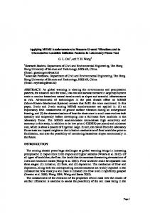
4. Fabrication and Characterization The accelerometer was fabricated in imec’s SiGe MEMS technology, which can later be used for integrating the accelerometer with CMOS in a MEMS-last approach [4]. The poly-SiGe layers are deposited by using a combination of chemical vapour deposition (CVD) and plasma enhanced CVD (PECVD) at 450ºC [5]. To achieve the 500 nm (Figure 3(a)) narrow trenches in the 4 μm thick SiGe layer (aspect ratio 8:1), precision i-line lithography in combination with a thin Si-oxide hard mask and deep reactive ion etching is used. The characterization of the device has been performed by using a Semi automatic probe station and impedance-analyzer. An AC signal sweep of 5-30 kHz with a amplitude of 100mV and a DC Bias of 700 mV has been applied to one pair of electrodes with the proof mass set to the ground. The fabricated device (Figure 3(a)) has a resonance peak at 20 kHz and a Q value around 5 in air (Figure 3(b)). For an open loop system with this Q value, the 3 dB bandwidth is 10 kHz and the 1% bandwidth is around 2 kHz (Figure 2(a)). 1.40E-08
Conductance ( Siemens)
1.20E-08 1.00E-08 8.00E-09 6.00E-09 4.00E-09 2.00E-09 0.00E+00 -2.00E-09
0
10000
20000
30000
40000
frequency (Hz)
Fig. 3. (a) Fabricated poly-SiGe accelerometer & detail of finger gap; (b) Measured resonance frequency of the accelerometer
5. Conclusion A single axis capacitive accelerometer sensor structure with interdigitated comb configuration has been designed, fabricated and tested. The design was optimized in order to have both a good sensitivity and a large bandwidth. Lowering the gap between the fingers to 500nm, results in a calculated sensitivity of 1.7 fF/g combined with a 10 kHz 3dB bandwidth. The measured resonance frequency of the fabricated structure is in good agreement with the simulations. The above results show that, by using narrow high aspect ratio gaps, a miniaturized sensitive accelerometer with a high bandwidth can be realized. References: [1] Yazdi.N, Ayazi.F, Najafi.K, “Micromachined inertial sensors” Proceedings of the IEEE, vol. 86, NO. 8, August 1998. [2] G.Langfelder et al “MEMS Motion Sensors Based on the Variations of the Fringe Capacitances” IEEE Sensors Journal (2011) ,Volume: 11, Issue: 4, Pages: 1069-1077 [3] http://www.coventor.com/products/coventorware/ [3] http://inst.eecs.berkeley.edu/~ee245/fa11/solutions/EE245_Fall_2011_HW1_Solutions_Final_2.pdf [4] A. Witvrouw, CMOS-MEMS Integration Today and Tomorrow, Viewpoint set no. 44 ‘The Materials for MEMS’, Scripta Materialia, Volume 59, Issue 9, pp. 945- 949 (2008)