geo-routing algorithms typically employ a face routing recovery scheme that allows ... common to find autonomous underwater vehicles (AUVs) acting as mobile ...
IEEE ICC 2012 - Ad-hoc and Sensor Networking Symposium
Signal Reflection-enabled Geographical Routing for Underwater Sensor Networks Lloyd Emokpae and Mohamed Younis Department of Computer Science and Electrical Engineering University of Maryland Baltimore County Baltimore, MD 21250 {lemokp1,younis}@cs.umbc.edu position information in the routing process [3]. A geo-routing algorithm can either serve unicast, multicast, geocast or anycast. A geocast is a special case of multicast in which the recipients are collocated in specific geographical regions. Geocast is popular in sensors networks where queries can be disseminated to solicit data from nodes in some area or when the data is sent to a mobile sink whose trajectory is not precisely known. Anycast often serves applications in which multiple sinks exist and it is necessary to reach any of them. Distributed geo-routing protocols often employ greedy forwarding techniques, whereby the packet is forwarded to the next hop closest to the destination node. Although this strategy simplifies the routing process, it is still prone to a local minimum. A local minimum is a node that is closest to the destination than any of its neighbors, but no link exists connecting the node to the destination due to blocked line-ofsight (LOS) paths. Furthermore, most geo-routing algorithms do not take into consideration the physical layer characteristics and antenna model as cross-layer optimizations in the routing process. To address these concerns, we propose GORRILA, a geographical optimized reflection-enabled routing algorithm that is immune to link ambiguity. GORRILA aims to establish the best stable unicast route from a sender to a group of destination nodes within a specific geocast region as depicted in Figure 1. Unlike traditional Euclidean distance based routing protocols, GORRILA not only relies on the LOS link between one-hop neighbors when establishing routes but considers other reflected paths while routing packets to neighbors. GORRILA factors in two NLOS links (or eigenrays), which are the refracted-surface-reflected (RSR) and refracted-bottom-reflected (RBR) eigenrays. Utilizing
Abstract—The 3-D nature of the underwater environment has made geographical-routing a popular choice in underwater acoustic sensor networks (UW-ASNs). A geographical (geo) routing protocol works by using the position information to find the best route from a source to a destination. These algorithms, often try to minimize the line-of-sight (LOS) Euclidean distance between hops, which is not always possible due to blocked LOS paths resulting in voids (or local minimum). Thus, traditional geo-routing algorithms typically employ a face routing recovery scheme that allows for back-tracking when blocked LOS links are encountered, which adds delay to the data delivery time. To overcome this, we propose a geo-routing scheme that does not depend on the LOS and utilize directional antennas to incorporate surface-reflected non-line-of-sight (NLOS) links in the routing process. Furthermore, the proposed algorithm is configured to optimize the route selection to achieve maximum network throughput. Simulation results are provided to validate the performance of the proposed algorithm. Keywords— geographical routing, underwater sensor networks
Acoustic
communication,
I. INTRODUCTION Recent years have witnessed growing interest in the use of underwater acoustic sensor networks (UW-ASNs) in many applications. Examples of these applications include environmental state monitoring, oceanic profile measurements, tactical surveillance and navigation [1]. For these applications, it is envisioned that a set of sensor nodes will be employed to collaboratively monitor an area of interest and track certain events or phenomena. In addition, it is common to find autonomous underwater vehicles (AUVs) acting as mobile sensor nodes in search-and-rescue missions and coastal patrol and working cooperatively to achieve a desired goal [2]. These AUVs will need to corporate in an adhoc manner to be able to establish and sustain communication links in order to ensure some desired level of quality of service (QoS) [1][2]. Moreover, communications between nodes rely on acoustic channels instead of radio channels since radio waves quickly get absorbed in the water medium. Establishing optimized paths for routing data packets is a very popular strategy for achieving the desired QoS, i.e., high throughput, as well as other design objectives, e.g., long lifespan [3]. In addition, the 3-dimensional nature of the underwater environment makes geographical (geo) routing a popular routing option since nodes can leverage the known
978-1-4577-2053-6/12/$31.00 ©2012 IEEE
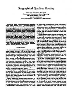
Figure 1: Underwater routing scenario showing the two geocast options from the source S1 to the mobile destination D10 (dashed line), and the source S2 to the mobile destination D16 (solid line). Our algorithm will be focusing on the unicast routes (red lines).
147
RSR or RBR links enables GORRILA to be robust to LOS link failures due to high network traffic or blocked paths that cause a packet to be trapped in a local minimum (i.e. voids) which has plagued most published geo-routing protocols. The main contribution of this paper can be summarized as follows: (1) An optimized physical (PHY) and medium access (MAC) cross-layer design, which factors in underwater acoustic transmission loss effects to optimize the route selection for maximum network throughput. (2) A novel GORRILA algorithm, which incorporates nonline-of-sight (NLOS) links in the routing process and utilizes directional antennas. The remainder of the paper is organized as follows. In section II, we discuss the related work in the literature. In section III we go over the system model. The throughput optimizer is described in section IV while section V describes the proposed GORRILA protocol in detail. The approach is evaluated in section VI and section VII concludes the paper.
distances. Our proposed GORRILA algorithm differs from [6] in two aspects; first our approach assumes k-hop neighborhood information, where k is the estimated number of hops to the destination node, and second our routing mechanism optimizes the route to achieve maximum network throughput. III. SYSTEM MODEL Utilizing NLOS (e.g., reflected) links would overcome many of the challenges in forming data paths among nodes in UW-ASNs. Basically, the NLOS links will enable robustness by overcoming obstacles and noisy LOS links. Moreover, it will boost the simultaneity of the transmissions and minimizes interferences among the different paths. In this section we highlight the potential of multi-hop routing with directional antennas when utilizing NLOS links. Given the lack of GPS and anchor information in the networking scenario in Figure 1, we have adopted an anchor-free relative localization scheme [8], which we employ to support geographical routing and directional communication.
II. RELATED WORK
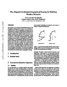
A. Multi-hop with Directional Antennas As mentioned earlier, utilizing NLOS will allow for simultaneous communication. To illustrate, let us consider Figure 2, where ���� is the LOS transmission range. With omni-directional antennas, multiple simultaneous transmissions cannot occur when nodes are within each other’s transmission range. As shown in Figure 2-(a), while the transmissions (� → � → ) are taking place, node cannot send packet to node � since it will interfere with the ongoing packet traffic. With directional antennas, in Figure 2-(b), two simultaneous multi-hop transfers ( → � → � → ) and ( → �) can take place, which increases overall network throughput. Figure 2-(c) shows that NLOS links can enable unique simultaneous multi-hop transfer scenarios by bypassing node B, which is the destination on another path. The scenario in Figure 2-(c) is not feasible with omni and LOS-directional transmissions.
Prior work on routing in UW-ASNs mainly focus on optimizing for energy consumption [3][4] or route robustness [5][6] with little attention given to optimize the network throughput. In [3], a vector-based forwarding (VBF) was used to compute the next hop of a traveling packet that essentially minimizes the traveling distance. VBF minimizes the number of forwarding nodes by adjusting the threshold of the minimum distance between two consecutive nodes on the route, which ultimately minimizes the network energy. An extension to the VBF algorithm was given in [5], which stores the routing vector on each forwarding node rather than a network-wide routing vector to increase redundancy. This allows each node to adaptively make packet forwarding decisions based on its current location, and thus enhancing data delivery ratio in sparse networks. A depth-based routing scheme was proposed in [4]. The approach is to use the depth information of each node to route packets to the desired destination node on the water surface. Hence, this approach can only route packets floating sink nodes. In [6], the authors proposed three reliable data delivery mechanisms for UW-ASNs. The first method does not require any position information about the neighbors and uses a limited-flooding technique to get to the destination. The second method assumes that the transmitting node has one-hop neighborhood information. In this case, the sender will insert in the packet the ID of its next hop node that is closest to the destination. The last method assumes that the transmitting node has two-hop neighborhood information which enables the node to avoid collisions within one- and two-hop
Figure 2: (a) Multi-hop with omni-directional antennas. kLOS is the line-of-sight transmission range, shown for node A.
IV. PHY/MAC CROSS-LAYER OPTIMIZER In this section we will go over acoustic transmission loss and present PHY/MAC layer based optimization will be employed by the GORRILA algorithm in selecting data paths that maximize the network throughput. A. Acoustic Transmission Loss The slow propagation delay in the underwater channel makes PHY/MAC optimization a challenge. According to [7] the sound speed ( ) is dependent on the temperature (�) in degrees centigrade, salinity (�) in parts per thousand, and depth (�) in meters. This can be expressed mathematically as:
(b) Multi-hop with directional antennas enables multiple simultaneous transmissions
148
(c) Enabling reflections while using directional antennas yields an increase in simultaneous transmissions
= 1449.2 + 4.6� − 0.055� � + 0.00029� � + (1.34 − 0.01�)(� − 35) + 0.016�
PYZ = P\Z ∙ (�, ", %) ∙ ^(%)
(1)
(7)
_`_a_b`
>i For (�, ", %) = 10 cd = � � !(")e f'A (%)� h , where 'A is the reflection coefficient for the rough water bottom or surface in (4) and (5) respectively for an antenna gain of ^(%) and a transmission power of P\Z . We can further define the antenna gain ^(%) at the beam steering angle % = %8 and for an array gain of AG as:
In general, there are three main causes of transmission loss in an underwater environment which are transmission loss due to multipath attenuation effects (������ ), transmission loss due to spherical geometric spreading(����� ) and transmission loss due to plane-wave attenuation, i.e. absorption (������ ). The total transmission loss in decibels can be expressed mathematically as: �� ����� = ������ + (����� + ������ ) �� ����� = ������ + �����
^, mnVU�UpE qUsVtu VqEVVt ^(%) ≅ k
v(% = %8 ), UpE qUsVtu VqEVVt
The directivity index of a directional antenna at the beam steering angle %8 can be expressed as: v(%8 ) = 10 ∗ logf (%8 )h with directivity (%8 ) = 4W/x(%8 ). x(%8 ) is the beam area depending on the antenna pattern at the beam steering angle % = %8 . In the next subsection, we derive expressions for the network throughput optimizer that will be based on the received power expression in (7).
(2)
[��]
where we have now grouped the spherical geometric spreading ����� and plane-wave ������ transmission loss to what we define as the line-of-sight (LOS) transmission loss ����� . In shallow water most of the transmission loss is due to the attenuation from multipath effects. The LOS transmission ����� (in dB) has the following frequency-distance dependent relationship: ����� = � ∙ 10 log(�) + � ∙ 10 log !(") [��]
B. Throughput Optimizer The network throughput optimizer starts by deriving the saturation throughput for a PHY/MAC cross-layer utilizing the CSMA/CA protocol. According to [9] the CSMA/CA saturation throughput is defined in as the ratio of the average payload transmitted during one slot to the average slot duration as shown: Average payload transmitted during one slot �y = Average slot duration
(3)
where � = 2 is the spherical spreading factor, " is the frequency (in kHz), !(") is the attenuation due to absorption in units of dB/km and � = ���� is the LOS transmission range in meters. The multipath transmission loss ������ can be determined by modeling the shallow water environment as a homogeneous fluid-fluid media where the top layer is the water layer and the bottom layer is the oceanic bottom in a shallow water environment. In the water layer the parameters { # , $# , %# } corresponds to the speed of sound (in m/s), the density (in kg/m3) and grazing angles (in radians). The same applies for the parameters { & , $& , %& } in sea bottom. Hence, using Snell’s Law we have: '=
�y =
*- /- /8:;