Simulating Dynamic Spectrum Access using ns-3 for Wireless Networks in Smart Environments Abdulla Al-Ali and Kaushik Chowdhury Department of Electrical and Computer Engineering Northeastern University, Boston, MA, U.S.A. E-mail:
[email protected],
[email protected] Abstract—Sudden spectrum demands may occur in dense and congested cities, which stress the communication infrastructure. At these times, identifying alternate spectrum bands through cognitive radio (CR) technology will allow users to maintain connectivity and relieve data congestion in the unlicensed bands. However, deployment of the CR networks must be preceded by accurate simulation of these networks, given the high infrastructure costs involved in their installation. Moreover, CR protocols are often cross-layered, which cannot be trivially implemented in off-the-shelf hardware. This paper proposes a framework for the network simulator 3 (ns-3) that is suitable for large networks. Our approach introduces several CR capabilities, such as spectrum sensing, primary user detection, and spectrum hand-off. Our simulator demonstrates improvements in execution time and memory usage, when compared to the earlier versions implemented for the ns-2 environment. This paper is accompanied by the release of the full source code for further research and improvement.
I. I NTRODUCTION Smart cities of the future will rely on the presence of ubiquitous wireless connectivity to empower its power grid, transportation systems, emergency responders, and the general public. The need to accommodate high bandwidth content becomes more acute in congested areas, and when a special event, such as a sports game, is planned. Moreover, urban environments offer additional challenges caused by propagation effects in certain portions of the spectrum, due to shadowing and reflection from tall man made structures. Cognitive radio (CR) offers the means to alleviate the spectrum shortage by adapting to the spectrum availability over multiple different bands, including TV frequencies, going beyond the unlicensed channels. CR enabled devices can automatically sense the licensed channels and infer activity of the Primary Users (PUs) in these bands. If multiple such licensed channels are available, CRs make intelligent spectrum switching decisions based on a high level policy. When planning the deployment of CR networks or testing a new protocol, researchers face uphill challenges given the challenging environment in which these networks operate. The CRs must quickly determine which licensed channels in the city are available, and make use of this spectrum before the PU reclaims it. Accurate protocol operation is critical, as any prolonged use of the channel raises concerns of interfering with the activities of the PUs. This concern directly translates to meticulous testing of the protocol or networking concept in a controlled environment. Given the costs of purchasing c 2014 IEEE 978-1-4799-4657-0/14/$31.00
multiple software defined radios and deploying them in a city, which will serve as the hardware building blocks of CRenabled smart city network, and the time investment in writing and deploying code in them, accurate computer simulation often becomes the methodology of choice. While several commercial simulators exist, such as OPNET [1], which can capably simulate heterogeneous networks, our focus in this work remains on affecting improvements for open-source use. In summary, the main challenges in CR network simulation are as follows: • CR protocols are generally cross-layered. Any change in one layer, such as spectrum sensing duration at the physical layer (PHY), has direct impact on the decisions made in the upper layers of the protocol stack, requiring extensive code changes throughout the stack. • The testing time increases dramatically with the complexity of the protocol. Owing to the large number of variables that can be controlled, identifying the dominating factor that impacts the environment to the greatest possible extent may force large number of costly trial runs. • The inter-dependence of the protocol layers requires network architects to implement more than one layer. For e.g., spectrum sensing at the physical layer (PHY) can impact the TCP throughout and its interpretation of congestion. Thus, the expertise required to simulate CR networks effectively is more than conventional wireless networks. • New functions unique to the area of CR, such as spectrum sensing, spectrum hand-off and licensed or primary user (PU) detection need to be embedded in the simulator. This paper is focused on providing the first cognitive radio extension to the network simulator 3 [2] or ns-3, which is a discrete event driven simulator. It is suitable for large scale simulations, which reflect better the practical, city-wide deployments. Moreover, ns-3 simulator is poised to replace its widely popular predecessor, network simulator 2 or ns-2 as it several advantages: (i) it has a new core written in C++, (ii) it is geared for wireless communications, (iii) it offers mobility schemes that are crucial for realizing vehicular networks that will play a role in smart cities, (iv) it has an organized modular architecture that is expandable, (v) it includes intuitive and extensive documentation via the html Doxygen [3] interface, and (vi) the same ns-3 code can be easily adapted to work in real devices [2]. Additionally, several more accurate highway
mobility extensions such as [4] can also be incorporated in the simulation scenarios, thereby reflecting the road layouts that actually exist. Despite the clear superiority of this new simulation platform, ns-3 lacks implementation support for CR networks. To bridge this gap, several changes are required in various network layers in ns-3. For example, a device needs multiple wireless interfaces to transmit, receive and negotiate with neighboring nodes. The PHY need to be able to sense and detect PUs, the medium access control (MAC) needs to decide and initiate hand-off to another available channel when a PU is detected, and the routing protocol needs to exchange the neighboring nodes’ current listening channel. Based on the recent Federal Communications Commission (FCC) mandate [5] that requires CRs to use a centralized spectrum database, the simulator will have to also incorporate such querying capabilities to identify the available channels using these databases. Our main contribution is to fully realize the first CR extension for ns-3 that has the following features: • It provides CR capabilities at the different network layers such as sensing, PU detection, channel hand-off and decision making. • It incorporates the ability to query a database to obtain PU activity results. • It has the ability to simulate cognitive with non-cognitive legacy wireless nodes in one test environment. • It includes seamless support for multi-channel and multiradio node architectures. • It provides new application programming interfaces (APIs) to expose the creation of these node-level and network-level features without advanced code changes. It comes with extensive documentation through Doxygen. • It allows studying the overhead, performance, and comparison with an existing extension of CR in ns-2. • It is accompanied by the release of the full source code, with additional guides on how to compile and run trial examples. The rest of this paper is organized as following: Section II discusses the existing network simulators, and their utility in implementing work for CR networks. We describe the model of our proposed approach in detail in Section III, followed by the proposed changes to the networking layers in ns-3. Performance evaluation studies are presented in Section IV, and finally Section V concludes the paper. II. R ELATED W ORK AND BACKGROUND To the best of our knowledge, no previous CR implementation exists for ns-3. There are, however, few modules for CR that has been built for other simulators. Cognitive Radio Cognitive Network (CRCN) [6] is a simulation framework designed for ns-2 that provides multi/single radio and multichannel support per node. It provides APIs that return information, such as the current noise or traffic conditions at a given channel, and provides a mechanism for channel handoff. CogNS [7] is another extension for ns-2 that allows one
network interface per node that is able to sense PU activity, and defer to another free channel based on a proposed spectrum decision algorithm. Nodes created in this environment cannot incorporate multiple radios per node. [8] provides a CR simulation extension for OMNeT++ [9]. It provides support for multiple interfaces per node, and is focused on evaluating CR MAC layer protocols. [10] is a simulator written in C++ for CR networks. The proposed simulator offers a modular approach that provides a full network layer stack. Because this work has not been extensively tested by the general networking community, this simulator involves some overhead in porting the well established protocols in changing environments. For e.g., for a researcher interested in simulating CR networks with an alternate MAC, such as a different 802.11 standard, the effort required is prohibitive. As compared to this, other popular simulators such as OMNet++, ns-2 and ns-3 already provide a wider user-base and support community. The work described in this paper uses the ns-2 CRAHN extension in [11] as the starting point. This earlier CR extension provides three network interfaces per node; a control interface to exchange control information between neighboring nodes, a receiving and transmitting interface. The CR module also incorporates hand-off and sensing capabilities at the PHY and MAC layers. It provides for PU detection mechanisms based on a PU activity model table that is loaded in the simulator a-priori. Our work, while based on this extension, has the following key differences: all the work that is proposed in this paper is based on the new ns-3 simulator, which (i) requires extensive code change, (ii) provides dynamically adjustable sensing/hand-off times that can be configured from the command line, (iii) is able to include cognitive and non-cognitive interfaces in one node, and (iv) is able to mix cognitive and non-cognitive nodes in one test environment. The simulation extension we propose can also incorporate a larger number of cognitive interfaces and/or nodes compared with ns-2 (in the order of thousands). We also design a different simulation architecture, composed of a spectrum manager block that hides or masks the inner CR API calls, leading to an organized modular approach. Overall, our proposed extension provides easy access to the specialized CR functionalities compared to other existing simulators through APIs, offers flexible CR and non-CR nodes to coexist, and incorporates advanced abilities, such as querying the recently mandated FCC database to infer PU activity. Our work aims at realizing a complete CR simulation platform to save time and resources for CR researchers who are either forced to write the entire CR software stack or embark on the costly enterprise of purchasing multiple real devices. III. N S -3 S IMULATOR M ODEL FOR CR In this section, we present the architectural model of our proposed ns-3 extension. We first describe the building blocks of the extension, followed by an explanation of the needed changes at various network layers for a given node.
Radio Environment
Transmitted Signal
Spectrum Mobility
Spectrum Sensing
Primary User Detection
Decision Request
Spectrum Hole
Spectrum Sharing Channel Capacity
Fig. 1.
Spectrum Decision
Spectrum Characterization
Cognitive cycle [12]
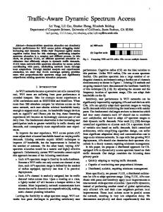
A. Building blocks for the simulator The typical functions of the CR node, follow the essential stages of Spectrum Mobility, Spectrum Sharing, Spectrum Sensing and Spectrum Decision, as described in the cognitive cycle described in [12]. As seen in Figure 1, these operations may occur one after the other, moving the CR node from one operational stage to the next. We use a similar approach to design the ns-3 simulator, by implementing each of these constituent blocks of the cognitive cycle, as shown in Figure 2. The spectrum management global block serves as a black box to the other modules in ns-3. Different layers in the network simulator keep a reference to the Spectrum Manager instance and tie their cognitive functionality via exposed APIs and hooked listeners. An example of such APIs are startSensing(), startHandoff(channel), isSpectrumFree(channel), alertNeighbors(). Internally, the Spectrum Manager block contains several submodules that map to the cognitive cycle, which are described next. • Spectrum Sensing/Database Query. This block is responsible for checking whether a PU exists in a given channel within a specified period of time. It infers the PU activity from a static PU Database that is loaded before the simulation starts. This submodule can be used to either (a) mimic sensing with a given probability of sensing error Perr , or (b) query an FCC approved database to determine the PU activity. The PU database that is loaded into the simulator is a text file that defines the number of PUs, their current occupied channel, the transmission power to determine the range, and a list of on (P Uon ) and off (P Uof f ) times. A researcher can create and load this text file with any given P Uon and P Uof f distributions such as normal or exponential. • Spectrum Decision. In this block, several policies are implemented. First, a policy in incorporated to determine whether a hand-off should be performed based on sensing/querying results. Second, a policy that determines to which channel a hand-off should happen is written. Note that these policies are extensible: One can implement different and independent policies, or extend the existing ones. A global repository is linked to this submodule which hosts current occupied channels by all CR nodes in the simulator. This can be used, for example, to determine
Fig. 2.
The main building blocks of the proposed extension
the least occupied channel that a node should switch to to guarantee desired Quality-of-Service (QoS). • Spectrum Mobility. This submodule initiates the handoff protocol in the current node. It is tied directly to the PHY layer in the ns-3 node which will be discussed later in Section III-B. • Spectrum Sharing. This submodule uses the built-in carrier sensing MAC 802 11 standards in ns-3 to make sure that the available spectrum is shared in a collisionfree manner between the CR nodes that chose to transmit on this same channel. These sub-blocks are linked internally whenever a given API in the Spectrum Manager block is invoked. For example, to initiate sensing, a researcher may invoke a call to the startSensingAndSwitchIfNecessary() API from any arbitrary network layer. The Spectrum Sensing block will then initiate a look-up via the PU Database, call the Spectrum Decision block once sensing is performed. If the Spectrum Decision block decides to switch to a new free spectrum, it initiates a hand-off via a call to the Spectrum Mobility block. The same network layer that invoked the call will then be notified via a listener once this cycle is completed and transmission can be resumed. This can be used, for instance, in a transport layer protocol where the transport protocol needs to determine when to resume the data flow [13]. B. Layer-specific modifications to ns-3 In this section, we detail the needed changes to each layer of the protocol stack for a given CR node in ns-3. Figure 3 depicts an overview of these changes. As can be seen, the proposed CR extension exposes several APIs and listeners to all the networking layers. We also make use of ns-3 tagging feature. The method to ‘tag’ a packet with some information helps to determine that packet’s internal routing in a given node, thereby avoiding the costly overhead that would ensue if said information was to be integrated into the packet’s header instead. More details on this feature and how it is used will be discussed, as we explain the changes to each of network
layers. 1) All layers up to the transport layer: No changes are proposed to these layers. However, all the Spectrum Manager’s APIs and listeners are exposed to these layers so a network researcher working on a CR application, for example, can make use of the CR features of the node by calling the respective APIs in the Spectrum Manager. 2) Transport layer: Our framework modifies this layer so that any packet that is generated here will be tagged as a DAT A packet. This information will be processed by the lower layers to determine the correct routing of such packets. This change affects all transport layer protocols defined in the simulator such as TCP, UDP, and potentially any new transport protocol that a researcher might be interested in implementing. 3) Network layer: For CRs to work in an ad-hoc topology, some information must be exchanged between neighboring nodes to determine listening channel of each member of the network. We extend the information carried in the packets of the AODV protocol [14] to include the current listening channel of each node. This information will be passed along with every HELLO, RREQ and RREP messages. Every packet that is generated by AODV is tagged as CT RL or control packet. This tag will be used by the lower layers to route the packet to the correct MAC interface. Moreover, the address resolution protocol (ARP) [15] is extended to route the packets depending on their tag to the correct MAC interface on the destination node. A detailed discussion on the MAC at the link layer and physical layer changes is given next. 4) Link and physical layers: We have undertaken substantial changes in both these layers. First, we define a new concept of Cognitive Interface (See Cognitive Interface block in Figure 3). A CR node may define any number of these cognitive interfaces. Each interface constitutes of three separate MAC-PHY layers; the first is for communicating control packet information on a common control channel. For e.g., AODV and ARP messages will be communicated over such an interface. We call this interface the CT RL interface. The second is used to transmit data messages to neighboring nodes (T X). This interface is switchable; i.e., it switches between different channels to transmit queued data packets that are destined to different nodes (and possibly, different listening channels). The switching and transmission times can be defined using the ns-3 attribute system. This system is a mechanism to pass parameters on the command line without the need to recompile the core of the simulator to change the value of various exposed parameters. There are several TX interface switching policies that we defined in our simulator, such as round robin, random, and switch between ‘active’ channels that imply channels that currently have packets awaiting transmission in the MAC queue. Finally, a switchable receiving interface RX is present, which senses for PU activity, hand-offs when PU is detected and alerts the neighbors about its new channel selection via an AODV HELLO packet. The transmission, sensing times, and probability of detection error can all be defined using the ns-3 attribute system. We emphasize that the Cognitive Interface makes
Fig. 3.
New layered architecture of an ns-3 CR node
Fig. 4.
State machine of the RX interface
all these new calls through the Spectrum Manager block. This provides a cleaner and easier cross-layer referencing as opposed to having each layer hold references to several other network layers. The tagging mechanism that was discussed earlier in the transport and network layers are used here to determine which interface a packet should be sent on. The TX Distributed Coordination Function (DCF) is also modified to store enqueued packets into different MAC queues based on the channel that they should be transmitted on. This will help the T X interface select which packets to transmit when it switches spectrum. At the physical layer (PHY), a new sensing state is added. The functionality of the sensing state is similar to that of the hand-off state where the PHY layer instructs the DCF to halt dequeueing from the respective MAC queue, while the sensing or hand-off operation is ongoing. The sensing and hand-off times can be defined using the ns-3 attribute system. The sensing state in the PHY layer uses the Spectrum Manager APIs which query the PU Database (See Figure 2) to determine PU activity. Note that the PHY layer can switch between any number of defined channels. These channels can have a different frequency, propagation path loss and delay models, as defined by the default ns-3 simulation environment. C. RX interface cognitive cycle When the RX component in the Cognitive Interface starts sensing, hand-off or transmit data, it transitions along the
UDP Throughput in CRE-NS3 (1 hop) 120
UDP throughput - CR
Throughput KB/s
100 80 60 40 20 0 0
50
100 150 Time (seconds)
200
250
(a)
Fig. 5. UDP flow’s throughput vs. time in a CR network. Gray areas indicate PU activity.
Fig. 6.
(b) Simulated CR network topologies (a) and (b).
CPU and memory utilization for NS3 vs. CRE-NS3
IV. P ERFORMANCE E VALUATION In this section, we first validate the proposed module by running a single UDP flow from one CR node to another. We study the performance overhead when comparing ns3 with our cognitive radio extension (abbreviated as CRE-NS3), and finally evaluate CRE-NS3 versus the previous iteration of this module for ns-2 (CRAHN [11]). The environment where the next set of evaluations is conducted is an Arch Linux 64-bit distribution with Linux kernel v3.13.5. The CPU is an Intel Core i7 860 clocked at 2.80 GHz. All simulations were performed in a single thread/core. The installed RAM has a total capacity of 16 GB. In the simulations below, the nodes perform sensing and data transmission in intervals of 100ms and 1s, respectively. The CR interface channel switching delay is set to 25µs. The wifi MAC standard is set to 802.11g with a rate of 54 M bps. We define a total number of 11 channels that the PUs and CR users can switch to. A. Validation The purpose of this evaluation is validate the CR extension by showing the throughput of a UDP flow with a constant data rate of 512kbps or 62.5KB/s from one CR to another. Both nodes are subject to PU activity that follows an on-off exponential distribution with average duration of 2s and 10s, respectively. Figure 5 shows the stream’s throughput at the
2
15
10
1
5
0
Memory util. (Megabytes)
CPU util. Mem. util. 20 CPU util. (seconds)
cognitive cycle depicted in the state machine in Figure 4. The cycle is first triggered by the Sense state. If no PU activity is detected, the state moves to the Transmit state, and after a predefined period of data transmission, returns back to the Sense state. If a PU is found, the state machine moves to the Decision state. Based on the policies executed, if the decision is to stay on the PU occupied channel, then no transmission will happen and the state immediately returns back to the Sense state. If a hand-off is decided, the decision block also decides which channel the hand-off should occur to. After this, the state machine moves to the Handoff state. Once the hand-off is completed, sensing is triggered again before confirming the PU’s vacancy and the data transmission resumption.
0 NS3
CRE-NS3
Fig. 7. Memory utilization vs. total CPU execution time (kernel + userspace) for both NS3 and CRE-NS3.
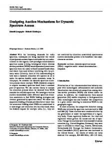
sink. The gray areas indicate the times when the PU is active. In this simulation, the switching policy is set to never (i.e. nodes do not switch to a vacant channel when a PU is detected, instead, they continue sensing until the channel is vacant). This choice was made to emphasize the disruption of data whenever a PU is active. We can clearly see that the flow is disrupted every time a PU is active. We also observe that the throughput receives a spike whenever (a) the PU vacates the channel, and (b), whenever the nodes perform sensing for 100ms. Both of these spikes are explained by the flushing of the MAC queue that accumulates packets while the nodes wait for the PU to vacate or when the nodes perform sensing. B. CRE-NS3 overhead In this evaluation, the nodes are placed in a topology as indicated by Figure 6(a). Each node sends constant rate data at 512 kbps to the immediate neighboring nodes as indicated in the figure by the arrows for a total of 250 s. A set of 20 simulation runs are executed for a non-CR network, and then again for a CR network. The total execution time (kernel and userspace in Linux’s time tool) and the maximum memory consumption using Valgrind’s massif tool [16] are then averaged over the 20 runs. Figure 7 shows the increase in both CPU utilization and memory consumption by our
also offers flexible policy-based decision making. We have introduced substantial changes to the transport, network, link and physical layers in ns-3 to incorporate the aforementioned CR features. Our evaluations also show minimal processing and memory overhead when running the extension as opposed to the base ns-3, and lower memory and processing time when compared to that of the previous CR extensions developed for ns-2.
CPU execution time
Execution time (in seconds)
3000
ns2 ns3
2500 2000 1500 1000 500 0 0
2
4 6 8 10 The square root of the number of nodes
12
Fig. 8. Total CPU execution time (kernel + userspace) for both CRE-NS3 and CRAHN. Memory (RAM) utilization
R EFERENCES
1000
Memory (MB)
ns2 ns3 100
10
1 2
Fig. 9.
ACKNOWLEDGMENTS Abdulla Al-Ali is supported by the Qatar University Ph.D. scholarship fund. This work was supported in part by the U.S. Office of Naval Research under grant number N000141410192.
4 6 8 10 The square root of the number of nodes
12
Memory utilization (MB) for both CRE-NS3 and CRAHN.
proposed module. The memory consumption increases by about 0.8 M B and the CPU execution time increases by about 10 s. The increase in both the execution and the memory consumption is mainly attributed to the fact that every CR node in the simulation has a combination of three total MACPHY interfaces instead of one (See Figure 3). C. CRE-NS3 vs. CRAHN Due to its similar architecture, in this section, CRAHN [11] in ns-2 is evaluated against CRE-NS3 for the same network topology as depicted by Figure 6(b). The number of nodes n increases with every simulation run until n = 13 or a total number of nodes of 13 × 13 = 169. If i and j are a node’s row and column index, then each node sends a stream to the nodes located at i + 1, j and i, j + 1 as depicted in the figure by the arrows. The stream that is sent from each node is a constant UDP flow with a bitrate of 512kbps. While the total CPU execution time is improved by a small margin in CRE-NS3 as shown in Figure 8, Figure 9 shows a substantial improvement (by an order of magnitude of 1) in the memory consumption for the same network topology. V. C ONCLUSION In this paper, we introduce the first cognitive radio extension for ns-3. In an era where spectrum scarcity in congested cities becomes a real problem, this new simulation environment will provide city network architects with a virtual platform that is able to perform the major spectrum-related adaptation. It
[1] X. Chang, “Network simulations with opnet,” in Proceedings of the 31st conference on Winter simulation: Simulation—a bridge to the futureVolume 1. ACM, 1999, pp. 307–314. [2] T. R. Henderson, M. Lacage, and G. F. Riley, “Network Simulations with the ns-3 Simulator,” in ACM SIGCOMM’08, Aug 2008, p. 527. [3] “Doxygen.” [Online]. Available: http://www.stack.nl/∼dimitri/doxygen/ [4] H. Arbabi and M. Weigle, “Highway mobility and vehicular ad-hoc networks in ns-3,” in Simulation Conference (WSC), Proceedings of the 2010 Winter, Dec 2010, pp. 2991–3003. [5] “FCC, second memorandum opinion and order,” ET Docket No. 04-186, DA 11-131, January 2011. [6] “Cognitive Radio Cognitive Network Simulator,” [accessed 03Feb-2014]. [Online]. Available: http://faculty.uml.edu/Tricia Chigan/ Research/CRCN Simulator.htm [7] V. Esmaeelzadeh, R. Berangi, S. Sebt, E. Hosseini, and M. Parsinia, “Cogns: A simulation framework for cognitive radio networks,” Wireless Personal Communications, vol. 72, no. 4, 2013. [8] J. Marinho and E. Monteiro, “Cognitive radio simulation based on omnet++/mixim,” in Proc. of the 11th Conferencia sobre Redes de Computadores, 2011. [9] “OMNeT++ Network Simulation Framework,” [accessed 03-Feb-2014]. [Online]. Available: http://www.omnetpp.org/ [10] M. Zhan, P. Ren, and M. Gong, “An open software simulation platform for cognitive radio,” in Wireless Communications Networking and Mobile Computing (WiCOM), 2010 6th International Conference on, Sept 2010, pp. 1–4. [11] M. D. Felice, K. R. Chowdhury, W. Kim, A. Kassler, and L. Bononi, “End-to-end protocols for cognitive radio ad hoc networks: An evaluation study,” Performance Evaluation, vol. 68, no. 9, pp. 859 – 875, 2011. [12] I. F. Akyildiz, W.-Y. Lee, and K. R. Chowdhury, “CRAHNs: cognitive radio ad hoc networks,” Ad Hoc Netw., vol. 7, no. 5, Jul. 2009. [13] A. K. Al-Ali and K. Chowdhury, “TFRC-CR: An equation-based transport protocol for cognitive radio networks,” Ad Hoc Networks, vol. 11, no. 6, 2013. [14] C. Perkins and E. Royer, “Ad-hoc on-demand distance vector routing,” in Mobile Computing Systems and Applications, 1999. Proceedings. WMCSA ’99. Second IEEE Workshop on, Feb 1999, pp. 90–100. [15] D. C. Plummer, “An Ethernet address resolution protocol - RFC 826,” Nov 1982. [16] N. Nethercote and J. Seward, “Valgrind: A framework for heavyweight dynamic binary instrumentation,” ACM SIGPLAN Not., vol. 42, no. 6, Jun. 2007.