bus system designed for use in automotive applications [1]. Some of the ... A basic top-level view of the conformance test structure is shown in Figure 1. .... across multiple configurations by overloading the derived classes from the test files.
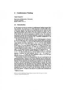
Simulation-Based FlexRayTM Conformance Testing – an OVM success story Mark Litterick, Co-founder & Verification Consultant, Verilab Abstract This article presents a case study on how the Open Verification Methodology (OVM) was successfully applied to implement a SystemVerilog simulation-based conformance test environment for next generation FlexRayTM 3.0 Communications System controllers. Complex application requirements and a need to run conformance tests on multiple vendor simulators, including Mentor’s Questa, with reliable, repeatable and identical results provided the design team with specific challenges. The OVM helped meet these challenges and proved that OVM has achieved its goal to “facilitate true SystemVerilog interoperability”. Introduction The FlexRayTM Communications System is a robust, scalable, deterministic, and fault-tolerant serial bus system designed for use in automotive applications [1]. Some of the basic characteristics of the FlexRay protocol include: are synchronous and asynchronous frame transfer, guaranteed frame latency and jitter during synchronous transfer, prioritization of frames during asynchronous transfer, single or multi-master clock synchronization, time synchronization across multiple networks, error detection and signalling, and scalable fault tolerance [2]. The next generation V3.0 of the FlexRay Protocol Specification [2] supports new applications such as drive-by-wire, through enhancements and additional features. From a verification point of view FlexRay is a challenge since it represents a complex and highly configurable protocol. This article discusses how the OVM was effectively applied an application typically handled by many directed tests implemented in hardware. The requirement was to implement a simulation-based environment capable of validating conformance of FlexRay Communications Controller devices, described at the Register Transfer Level (RTL), or clock-accurate behavioral level, with a set of very specific tests developed by the FlexRay Protocol Conformance Test Working Group and defined in an 800-page FlexRay Protocol Conformance Test Specification document [3]. A basic top-level view of the conformance test structure is shown in Figure 1.
The main requirements for the conformance test environment include: • • •
Deterministic repeatable operation across different SystemVerilog simulators Support for different target implementations from multiple suppliers Capability to run all tests with different configurations and modifications
In order to satisfy the requirement for identical and repeatable operation across simulators we had to ensure that all aspects of stimulus, including sequence and transaction field values and timing, were tightly constrained during test runs. However, using constrained random verification techniques and the OVM to implement such an environment meant that a flexible and extensible solution could be developed much more quickly than a large number of directed tests. SystemVerilog interfacing and multi-language support made it a natural choice to support the different Implementations Under Test (IUT) which could be coded in Verilog, SystemVerilog, VHDL or clock-accurate SystemC behavioral models such as the FlexRay Executable Model (FREM) used throughout the development phase. Mapping from the test environment Controller Host Interface (CHI) Abstract Physical Interface (API) to the physical registers of the IUT is provided by the CHI Adaption Layer shown in Figure 1; this enables the conformance test environment to remain independent of the IUT but requires an IUT-specific adaption layer to be implemented for each target device. OVM built-in automation allowed the scope of the test space to be easily managed. This was particularly important, as FlexRay has more than 60 node and cluster related configuration parameters which for the purposes of testing are organized into a set of basic configurations with additional test-specific modifications requiring more than 10,000 total test runs for the 430 tests specified in the conformance test suite.
Project Overview The project plan was broken down into three main phases which fitted in with OVM environment development goals and customer deliverable expectations: Phase 1: develop the main testbench architecture with all major building blocks in place. Demonstrate operation with both SystemC and RTL IUTs. Implement stimulus and checks for a small number of tests. Phase 2: implement 80% of the tests against the evolving Conformance Test Specification, including stimulus and checks but with allowances for unimplemented features and checks as well as failing tests. Phase 3: conclude 100% of the tests against the final release of the Conformance Test Specification, including all features and checks, with 100% explained test results.
•
•
•
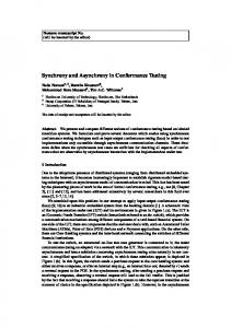
Figure 2 provides an overview of the project timeline and shows the test and environment development curves throughout the plan phases. The OVM was especially valuable in establishing the steep implementation ramp for environment capability during the initial phase of the project. During the test implementation phase the majority of activity was application-specific sequence, checker and model development. Note also that towards the end of the project the test implementation overtook the environment, since tests were required before all modelling corner cases and checking could be completed. 500 450 400 350 300 250
PLAN
200
TESTS
150
ENVIRONMENT
100 50 W20
W17
W11 W14
W5 W8
W51 W2
W45 W48
W39 W42
W36
W30 W33
W24 W27
W21
0
As shown in Figure 2 we managed to engineer the implementation of the overall conformance test environment to follow a quite linear pattern. In this case, as with many client engagements, we succeeded in our aim to perform agile, feature-based releases. After the initial development work we could perform functional snapshot releases of the environment at any stage with known stimulus and modelling features and checker capability and omissions. The secret here is to engineer the capability to support all the required features, get the communication structure and transactions
right, but once you are confident that it can be made to work, focus on the missing pieces of the puzzle rather than taking any particular thread all the way to completion. A key requirement, and one of the justifications for adopting a simulation-based approach, was the ability to adapt to the evolving Conformance Test Specification which was under development by the FlexRay Protocol Conformance Test Working Group in parallel with the implementation activity. In fact the scope and complexity of the test specification grew considerably during the project, partly due to contributions from JasPar [4] and partly due to increased protocol coverage goals, so Phase 3 was sub-divided into several intermediate milestones in order to control the deliverables. OVM Architecture The mapping of the conformance test environment to generic OVM component building blocks (such as sequencers, drivers, monitors and agents) is shown in Figure 3. The following key capabilities of OVM were used to full advantage in the conformance test environment: •
• • •
OVM factory was used to build all components in the environment, and was fundamental in managing the proliferation of configuration objects which allowed single tests to be run across multiple configurations by overloading the derived classes from the test files. Sequences were used as the basis for all stimuli providing a clean and consistent approach to stimulus generation and well encapsulated control from the test description files. TLM ports were used for all transaction level communication within the environment, for example between the monitors and the scoreboard OVM events were used for timing events, shared between components via an event pool
The basic operation of each of the sub-components is: •
•
•
•
Lower Tester Agent (LT) is responsible for emulating all of the cluster channel traffic and checking physical signals. It comprises a timebase agent and two instances of the channel agent. The agents contain sequencers, drivers and monitors. Tests interact with a virtual sequencer in the LT agent which in turn sends sequences to the appropriate physical sequencer. All checks are carried out by the monitors or in the scoreboard via TLM ports. The LT has extensive error injection capability and supports all legal and illegal traffic scenarios required by the conformance test suite. Upper Tester Agent (UT) is responsible for interacting with the IUT via the CHI software API and the IUT-specific adaption layer. Tests can interact with the UT sequencer directly to stimulate the CHI in order to control all operating modes, configuration, status, buffer, FIFO and interrupt operation within the IUT. Since there is no physical interface to monitor (only a software API) the checks performed in the UT monitor must also be stimulated directly by UT CHI sequences. Scoreboard is used to validate all traffic between the Upper and Lower tester which passes through the IUT. For instance if the model predicts that the IUT must send frames then these are posted to the scoreboard by the UT, when the IUT actually sends the frame the LT also sends transactions to the scoreboard for comparison – mismatches, out-of-order traffic or missing transactions all result in conformance test failures. Event Pool is used to share timing events between the Upper and Lower Tester (and also within the lower tester agent). Most of these events also communicate additional information by passing simple data structures (for example slot or cycle counts) as objects within the event.
A key design aim for the conformance test environment was to encapsulate the test files in such a way that they could be read and understood by non-verification experts. This was achieved in an OVM-like manner using macros for background tasks such as configuration class generation and environment build overheads. Since most of the checks were fully automatic in the monitors of the environment, this left concise sequence instantiation in the test implementation files with a very close match to the test specification requirements. For example, if the test description were: •
In cycle 9, the LT simulates a startup frame in slot 1 with wrong header CRC (bit flip in the LSB of the header CRC).
This is represented in the actual test as: `fr_do_lt_with(lt_er_seq,{ lt_ch == FR_AB; lt_cycle == 9; lt_kind == FR_STARTUP_PAYLOAD; lt_slot == 1; lt_error == FR_HEADER_CRC; })
As a result of the single sequence call in the test, sequences are executed on both channels with default values for all frame content including payload, as well as a timing sequence running in the timebase sequencer and all the downstream driver and CODEC functionality. In addition, the frame
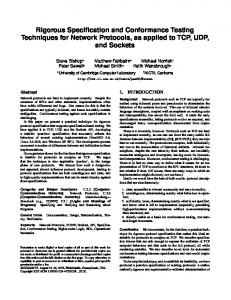
sent to the IUT is decoded by the channel monitors and sent to respective scoreboards for subsequent comparison when slot status is read at the end of the corresponding communication cycle. Users only need to handle calls to fr_do_lt and fr_do_ut macros – these in turn perform ovm_do_on_with sequence calls to the appropriate sequencer path inside the environment. The scope of the conformance test environment was such that about 130,000 non-comment lines of code were required for the final implementation. The approximate distribution of the code is shown in Figure 4:
Code Distribution 7% 11%
32%
Tests Sequence Library Config Library ENV Components
39%
11%
OVM Infrstructure
The pie-chart gives a good overview of the volume of code required for the different aspects of the project, but it does not accurately represent the development effort. For example the configuration library is a large portion, but is mainly generated automatically from the test specification file using a script (the implementation of which was of course considerable effort, but not 30% of the project). Sequences provided excellent reuse in the test specifications, resulting in considerable payback. The sequence definitions are relatively easy to replicate and build up into an extensive library; however, the much fewer lines of code required in the transaction definition and associated environment components are much more intense and time-consuming to generate. Pulling together test definitions from a library of sequences is not too difficult, but debugging the complex interactions of the sequences with the checkers and of course the IUT can be a much more time-consuming activity. One important thing to note is that the total project time spent on OVM infrastructure implementation was very small – with a working codebase from other projects to draw on we spent most of the project forgetting that OVM was even there. The infrastructure was pulled together quickly and the details of the methodology could be forgotten about. Simulator interoperability with the OVM was not a problem on the project. SystemVerilog language interoperability in the application code on the other hand consumed a lot of effort. Some problems were encountered with general language support, including different scoping rules, constraint capabilities for complex layered transactions and support for some basic syntactical constructs. In
total approximately 10% of project effort was consumed handling issues with multi-tool requirements: analysis, experimentation and validation of solutions. While this is expected to improve over time, our current recommendations are: • • • •
Build up awareness each tool’s capability Focus on one tool rather than getting bogged-down with parallel development Once you have extensive working regressions, bring the next tool into the mix Do not wait until the end to investigate code compromises that will work with all tools
Conclusion The Simulation-Based FlexRay Conformance Test Environment was a very challenging project with complex technical and multi-tool requirements. By successfully applying constrained-random verification techniques using the OVM we were able to demonstrate that OVM has achieved its goal to “facilitate true SystemVerilog interoperability” [5]. Throughout the project the Verilab implementation team were able to detect and report many issues with the SystemC Executable Model, the Conformance Test Specification, as well as some issues with the Protocol Specification itself. With the help of the OVM testbench the FlexRay Protocol Conformance Test Working Group could quickly analyse the issues, proposed fixes for the IUT and the specifications, and release updates at regular intervals. As well as achieving the obvious goals of pre-silicon conformance validation, improved debug resulting from RTL visibility, reduced cost, risk mitigation and improved quality for the IP providers, the project also facilitated highly effective validation of the evolving Conformance Test Specification thereby improving the quality and accuracy of the final document which benefits all FlexRay stakeholders from IP providers, through OEMs to automobile manufacturers. Acknowledgements Analysis and implementation of the Simulation-Based FlexRayTM Conformance Test Environment was performed by Verilab under contract to the FlexRay Consortium and we are grateful for permission to publish this article. In addition we would like to thank the individual members of the FlexRay Protocol Conformance Test Working Group for their support throughout the project. References [1] www.flexray.com : FlexRay Consortium [2] FlexRay Protocol Specification V3.0, FlexRay Consortium [3] FlexRay Protocol Conformance Test Specification V3.0, FlexRay Consortium [4] www.jaspar.jp/english : Japan Automotive Software Platform and Architecture [5] www.ovmworld.org : Open Verification Methodology