steam generator (hot and cold leg), and the primary pump with the attached ...... the condensate pump,preheater 1, the feedwater tank, the feed- water pump with ...
Æ>K S l O O ' f g - f
V o se
ii
cø
S
Æ
«T"?
RisO-M-2640
Simulation Model of a PWR Power Plant Niels Larsen
Risø National Laboratory, DK-4000 Roskilde, Denmark March 1987
SIMULATION MODEL OF A PWR POWER PLANT Niels Larsen
Risø National Laboratory, DK 4000 Roskilde, Denmark March 1987
Risø-M-2640
ISBN
87-550-1327-9
ISSN
0418-6435
Grafisk Service Risø 1987
RISØ-M-2640
SIMULATION MODEL OF A PWR PLANT Niels Larsen
Abstract. A simulation model of a hypothetical PWR power plant is described. A large number of disturbances and failures in plant function can be simulated. The model is written as seven modules to the modular simulation system for continuous processes DYSIM and serves also as a user example of this system. The model runs in Fortran 77 on the IBM-PC-AT.
March 1987 Risø National Laboratory, DK 4000 Roskilde, Denmark
CONTENTS Page 1. INTRODUCTION 2. REACTOR 2.1. Nuclear power 2.2. Primary loop 2.3. Reactor trip and failures
5
,
8 8 10 11
3. PRESSURIZER 3.1. Pressure calculation 3.2. Controller actions 3.3. Failures
14 14 19 20
4. CONTAINMENT ACTIVITY
23
5. STEAM GENERATOR
24
6. TURBINES AND CONDENSER
33
6.1. 6.2. 6.3. 6.4. 6.5. 6.6-
Steam line HP-turbine Reheater LP-tur bine Condenser Turbine trip and failures
33 34 37 39 40 41
7. FEEDWATER LINE 7.1. Feedwater flow 7.2. Preheaters 7.3. Failures
43 43 45 46
8. LUBRICATION OIL SYSTEMS
49
* 1
T
Sc-
upper plenum T up Fuel T u
avg
Inlet chamber T inl
TT
Connecting tube T * ct
CR
..-vl*
-LJ-VJ--Lower plenum IP
Cold leg T
cl Primary pump T P Motor
Lubrication oil system
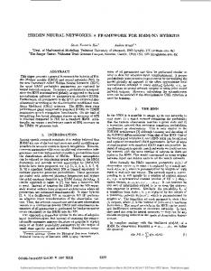
Fig. 2.1 Reactor and primary loop.
C: controller signal
- 14 -
3. PRESSURIZER
The pressurizer module consists of the pressurizer tank with the attached heating and spray cooling system, relief and safety valves. The module also includes the volume control tank with pump and valve. Fig. 3.1. shows the pressurizer module.
3.1. Pressure calculation Four combinations of thermodynamic states of water and gas phases within the pressurizer are comprised by the model: gas in saturated or superheated state and water in saturated or subcooled state. Energy and mass balance are used to calculate the pressure and water level. It is assumed that no heat exchange takes place through the tank wall. Also enthalpies of surge tube and spray cooling water are assumed equal to hot and cold leg conditions respectively. The gas and water phases are described as homogeneous. Steam bubles and spray cooling droplets are considered to belong to the gas and water phase, i.e. the calculated water level may deviate slightly from a measured level. In the derivations below the following notation is used: p density, V volume, p pressure, m mass, and h specific enthalpy. Indices: f water phase, g gas phase, s saturation. First the water phase energy balance gives
in saturation
is described. Mass and
dmfg d - T T -—(PfsVf) - Wi+Wc-We at at (3.1) —
(PfsVfhfs) - Q+Wihi+Wchfa-Wehgg+Vfp
- 15 where W^ and h^ are mass flow to pressurizer and enthalpy from surge tube, W c is the condensation rate in gas phase, W e the evaporation rate in water phase and Q heating power in water phase. Eq. (3.1) transform into
V f « (Wi+Wc-We-Vf
- p)/p fs
ah
W e « (Q-wt(h fs -h i )-V f ( Pfs
fs
(3.2.a)
0.1)p)/hf
(3.2.b)
aps where W"£ is the positive part of Wj and hf_ » h_g-hfs is the evaporation heat. The number 0.1 appears because non-SI units are used (cf. appendix A1}. Under subcooled conditions mass and energy balance give dmf a — «~
-wi+wc (3.3)
d ---(pfVfhf) « Q+Wihi+Wchfs+Vfp dt which transforms into apf V f « (Wi+Wc-V£((
• apf , ) hf+( ) p))/pf 9h P dp h
h £ - (Q+Wc(hfs-hf)-wt(hf-hi)+0.1Vfp)/VfPf
(3.4.a)
(3.4.b)
Under saturated conditions the water enthalpy hf (which is a state variable in the model) follows saturation value smothly as hf « (hf8-hf)/0,25
(3.2.C)
i.e. with a time delay of 0.25 sec. In the subcooled state We - 0
(3.4.C)
- 16 That is, water in saturated state is given from (3.2.a+b+c) and in subcooled state from (3.4.a+b+c). Hass and energy balance for the gas phase in saturated state gives drags —
d =
- £ < P g s V - w e +w k -w c -w r (3.5)
—
(VgPgshgs) = W e hg S +W k h k -W c h fs -W r hg S +VgP
where W k and h k are spray cooling rate and enthalpy of spray cooling water and W r is the flow of steam leaving as leak in gas phase and through relief and safety valves. Using Vg = -Vf eq. (3.5) transform into
P
" (Pg S Vf+W e +W k -W c -W r )/V g —— ^Ps 9hg S
Wc = (W k (hg S -h k )+Vg(p g 8
(3.6.a) #
0.1)p)/hfg
(3.6.b)
aps For t h e superheated dtru » We+Wk-Wr e dt * r —
state
(3.7)
(VgPghg) - WehgS+Wkhk-Wrhg8*VgP
which turn i n t o " (We+Wjt-Wr+PgVf-Vat—5) hq)/Vg( —~) 8h p 8p Ag - (W e (hg S -hg)-W k (hg-h k )+0.1Vgp)/VgPg
P
(3.8.a) n
(3.8.b)
Under saturated conditions gas enthalphy follows the saturation value
- 17 hg « (hg--hg)/0.25
(3.6.c)
and in the superheated state Wc « 0
(3.8.c)
That is, gas is described by (3.6.a+b+c) in saturated state and (3.8.a+b+c) in superheated state. In the water phase the switch from saturation to subcooling takes place when W e reaches zero and switching from subcooled to saturated state happens when hf reaches hf s from the lower side. Similar switches takes place in gas phase: from saturation to superheated state when W c reaches zero and from superheated to saturated state, when h g reaches h g s from the higher side. The state of the system determines which two of the four sets of equations (3.2), (3.4), (3.6), and (3.8) are to be used. However, the state itself is determined by values of variables calculated by these equations. This implicitness is solved by two iterations in which the equations are applied and the state is determined. Another implicitness arises using the equations for Vf and p. Therefore these equations are combined and solved for p. As an example consider the case of saturation in both phases. Rewriting (3.6.a) and using (3.2.a) yields
Vg
BPgs • • P - PgsVf+We+Wk-Wc-wr ?ps a Pgs Pfs. —2— (Wi+W c -W e -V f p) +We-»-Wjc-Wc-Wr
pfs
' aps
which gives p p p &Pgs Pgs fs • Pgs gs gs ( V g — — + -2=- V f )p - (1--2- )we + (-2- -i )Wc+ -2_Wi-W r +W k dps Pfs dps pfs Pfs Pfs
or p • Pgs gs Pgs F c p - (1--2-)We + "
d — (PfsVfrhfs)
+
W
ft+Wgt-Wfr-Wgr
d ~(PgsVgrhgs)
(5.18)
" Wfthfs+Wgthgg-Wfrhfs-Wgrhgs+Vrp Where Wft* Wgtr Wfr» and W g r are water and steam outlet flows from top chamber and riser. Eq. (5.18) transforms into «fr - Wft + Wgt-Wgr + Vgr(Pfs-Pgs)-P(-^ ? V f r +-^ V g r ) ops op s
(5.19)
•
• 1 P dhgs V Vgr « — ((Wgt-Wgr) - ^ < grAd v d « t *r d s Pgs Pgs Pgs ( ( - l c ( — a s +1-a s )-l t ( a t +1-a t )-l r ( a r +1-a r )+l+l d )g Pfs Pfs Pfs (Ap s +Ap t +Ap r +Ap d ) P
(5.30)
fs
where l c , lt» lr» an where Sputh i s t n e fraction of the total pressure and enthalpy drop through the turbine. The turbine power is now calculated as Eh
* Wh(hh-hho> " wphh(hsh-hho>
(6.14)
- 37 6.3. Reheater The reheater is divided into two sections, the moisture separator and the superheater. The inlet flow from the HP-turbine is given from W t - Wh-Wphh
(6.15)
After the water has been separated from the flow in the moisture separator the steam is assumed to contain 0.5% humidity, i.e. the inlet flow without water is
W tt ix =
*ho 0.995
Wt
(6.16)
and the specific inlet enthalpy is h t i = 0.995 h gs (p t ) + 0.005 h fs (p t )
(6.17)
Only one pressure node is used for the whole reheater, i.e. pressure is determined by • pt
w
ti"wro (6.18)
(Vt+Vr) — * 5p where Vt and Vr are volumes of the moisture separator and superheater compartments and w r o is the reheater outlet flow. This flow is calculated from Wro * Khl Aitv*lpv(Pt-Pl)
(6.19)
where pi is the LP-turbine inlet chamber pressure and X}pV is a user specified valve position (normally xipV » 1). The steam flow, Wtor from the moisture separator to the superheater section is calculated as a mean value of the reheater inlet and outlet flows
- 38 -
VrWti + V t W r o Wto =
(6 20)
vt,vr
"
Energy balance then gives the total enthalpy in the moisture separator compartement as Hrtv - Wtihti - W to hto
(6.21)
where the specific enthalpy is hfco
=
Hrtv
(6.22)
8
Vt
Pgs
"7T
Pt
ap Energy balance for the secondary side of the superheater gives the total and specific enthalpy Hrhv
=
Wtohto + Qrr - Wro^ro
(6.23)
H
hro =
rhv
(6.24)
dpgs
Vt_
57
Pt
where Q r r is the heat transfer from tube to steam, calculated as
Qrr » Kqr(Ttr-Trm)
Here Ttr i s the tube temperature and Trjn is a superheater mean temperature calculated from inlet (T ro ) and outlet temperature (T ro ) (cf. appendix D ) . The outlet temperature, T r o , is given from h ro -h gs (pt) T
ro » Tsat(Pt>
+
(6#26)
where pSg is the steam generator pressure and the feedwater pump pressure upset is given by A P p f « A 2 W^B 2 W f w «o f w p +C 2 u.^ w p
(7.7)
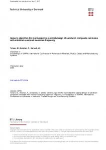
where u>fwp is the controlled pump speed (cf. section 9 ) . Peedwater temperature is raised to Tf w in preheater 2 before it enters the steam generator.
- 45 7.2. Preheaters The preheater model is shown in Fig. 7.2. Primary side steam enters at pressure Pi with specific enthalphy hi and condenses on the tube. The condensate is assumed to be saturated,i.e. the drain water temperature Tf is given from the pressure Tf - T sat (Pi)
(7.8)
A mean secondary side water temperature, Tf m , is calculated from inlet and outlet temperatures, Ti and T 0 (cf. appendix D ) . The heat transfer from steam to tube is given by Qst * K st (T f -T t )
(7.9)
where Tt is the tube temperatare. The heat transfer from tube to secondary side water is calcualted by Qtf
- Ktf(Tt-Tfm)
(7-10)
Then energy balance gives the tube temperature, the steam inlet flow, Hg, and the secondary side water (feedwater) outlet temperature as CtTt * Qst-Qtf
(7.11)
Qst W 9
CfT0
»
(7.12)
hi-h fs (T f ) = W f Cp f (Ti-T 0 )+Q tf
(7.13)
where Ct, Cf, and cpf are heat capacity of tube, water in tube and specific heat capacity of water. hfS is the saturated water enthalpy. It is assumed that no drain water accumulation takes place, i.e. the drain ojtlet flow equals the steam inlet flow.
- 46 7.3. Failures Failure signals on the two non-return valves can be set whereby the valves remain closed. A pump flow fraction for each pump can be set, reducing the pump flow no matter the value of the controlled pump speeds. Further a leak of water from the feedwater tank can be specified by the user. Failures in the lubrication oil system may cause the feedwater pump to stop. In this case the feedwater flow will decrease exponentially with a time constant of 10 sec. Physical data and steady state values for the module are found in appendix A7.
Preheater 2
X
1
L Feedwater k tank
Feedwater pump »Leak
0
Condensate nusiiaaiv • pump pump I
^
Prehaater 1
Motor
Lubrication oil system Fig. 7.1
Feedwater line,
- 48 -
Steam inlet ;
Feedwater
,
' Drain flow
Fig. 7.2
Preheater.
- 49 -
8. LUBRICATION OIL SYSTEM Two identical energy systea and feedwater ing (cf. Pig.
minor support systeias are attached to the sain lubricating the bearings of the priaary coolant puap motors and maintaining conditions for pulp8.1).
Lubrication oil froa a tank is puaped through a filter to the puap aotor. Oil is by-passsed to the tank in case of high pressure. The by-pass valve position is calculated froa
Po
where L Q is a possible user specified oil leak from the tank *Bd Motot i s
the
total oil content.
Equations (8.1), (8.6), and (8.3) form an algebraic loop which in most cases introduces numerical problems. In order to smooth out small oscillations in x 0 , Wra, and P 0 , these variables are calculated as a weighted sum of the actual value and the value from the previous integration step. Physical constants are found in appendix A8.
- 51 -
pump
Oil tank
Fig. 8.1
Lubrication oil system.
- 52 -
9. CONTROLLERS AND TRIP SYSTEM
In all eight controllers are comprised by the model. The location of each controller and the device they act upon are shown in Fig. 1.1. Further the figure shows which components are sensitive to a generated trip signal. The way the individual components react to controller and trip signals are described in the previous sections. This section describes how the controller signals are calculated and what events cause a trip signal to be generated. Each controller is described in the following sections. However, two features are common to all controllers. Each controller consists of one or several proportional-integral (PI) controller components. A Pi-controller is characterised by the transfer function
K(1 + — )
(9.1)
X8
where K is the amplification constant and x is the time constant. The equations for the Pi-controller are E =
XQ-X
z = e/x
(9.2)
y = K(e+z) where x is the input signal, x 0 is the setpoint value, e the error signal, z the integrated signal, and y the output signal. Further many controllers consist of one or more 1. order lags with time constant x characterised by the transfer function
— 1+xs
(9.3)
The equation for the lag is y * (x-y)/x
(9.4)
where x is the input signal and y is the delayed output signal.
- 53 9.1. Primary pressure controller, c^ The diagram of the primary pressure controller is shown in Fig. 9.1. This is a pure Pi-controller. The output signal controls the pressurizer spray cooling water valve, the proportional and back up heaters and relief valve 1. The pressurizer relief valve 2 is controlled directly by the primary pressure (cf. section 3). The pressurizer setpoint is specified by the user. Normal value is 155.1 bar.
9.2. Pressurizer water level controller, c? The »Hagram of this controller is shown in Fig. 9.2. The setpoint is ;,«ilculated fro.n a piecewirfe linear function of the reactor average temperature T a v g . The controller is of Pi-type giving the speed of the volume control tank pump. An overriding action of water level on the pr.*sf-v - ;:er heaters ' s not shown on the figure. Below 15% It-'el sY'.'. neaters are disconnected and when the level is 5% abo-••*» the reference level the backup heaters are turned on (cf. :.ction ~i).
9.3. Steam generate..- water level controller, c-^ The level control^ iiagrxiii is shown in Fig. 9.3. The relative water level is calculi . JJ as Wlv - (LSG+1.18)/5.92
(9.5)
with a normal value of 0.66. Here LSG is the level of the mixing chamber in the steam generator (cf. section 5). The setpoint is calculated from a piecewise linear function of relative nuclear power (cf. section 2). The input and setpoint signals go through 1. order lags, and the controller is of PI-type. The feedwater pump speed is calculated as a delayed sum of the Pi-controller output and the deviation of relative flows out of and into the steam generator.
- 54 9.4« Reactor power controller, C4 This controller of which the diagram is shown in Fig. 9.4 gives the reactor control rod speed. The reactor power is adjusted indirectly because this controller in fact controls the reactor average temperature, calculated as the mean value of the cold and hot leg temperature. This value is delayed and lead/lag compensated. The transfer function the lead/lag compensation is equivalent to the diagram of Fig. 9.5.a which gives the transfer function in terms of a simple integration (with time constant, T5, transfer function I/T5S) and a multiplication with X4/T5. The setpoint for the average temperature is calculated as a piecewise linear function of relative HP-turbine inlet pressure (which is a measure of turbine power) and further sent through a 1. order lag. A correction power mismatch between relative ;urbine and nuclear power is made. The equivalent diagram for the mismatch transfer function is shown in Fig. 9.5.b in terms of simple integration and multiplication. The power mismatch signal is sent through non linear and variable gains. The error signal, corrected for power mismatch is transformed into control rod speed in the rod speed function of which the graph is shown in Fig. 9.5.c.
9.5. Turbine power controller, c^ Figure 9.6 gives the turbine power controller diagram. The error signal is calculated from the sum of HP and LP turbine power and a user specified setpoint. Both HP-valve position
and flow are calcualted together here
thereby saving evaluations of the non-linear function, F v . The calculation of pressure.
HP-valve
flow
also
involves
the
steam
line
- 55 9.6. By-pass valve, secondary relief valve and feedwater tank level controllers, C6, 07, cs) All controllers are of simple Pi-type (cf. Fig. 9.7. a,b,c). The by-pass valve and relief valve controllers have fixed setpoints whereas the feedwater tank level setpoint is specified by the user.
9.7. Trip system Conditions for reactor trip and turbine trip are listed below. Because a reactor trip will cause a turbine trip and visa versa only one trip signal is generated. During non-trip periods the trip signal equals zero. When one of the trip conditions is met the trip signal will take a non-zero value according to the list below. The actions taken by various components of the plant are described in sections 2 and 6. A non-zero trip signal will override the rod speed controller (C4) output, generating a signal for control rod insertion with maximum speed. Conditions for trip; Turbine: High steam generator level (> 79.4%) High condenser level (> 70%) High condenser pressure (> 0.3 bar)
Trip signal 1
Reactor: High nuclear power (>109%) Low primary flow (< 84%) Primary pressure out of range
4
(range: 135.0-165.4 bar)
6
5
- 56 High pressurizer level (> 92%) Low steam generator level (< 19.9%) Manual scram signal (set by user)
7 8 9
9.8. Controller failures Two types of controller failures are possible for each individual controller. A controller may be set to drift; i.e. the controller output signal will start to drift either to its maximum or minimum value. The drift will start when the failure signal for the particular controller is set, continuously increasing or decreasing the output signal lineary to the maximum or minimum value within at most 30 seconds. If the drift signal is set, the drift will take place no matter what input the controller recieves. A controller may also be blocked; i.e. the controller output signal remains constant at its value when the failure signal is set, no matter the input to the controller. When either one of the two possible failure signals for a particular controller is set, integral signals of the controller are kept constant. For further details of failures and disturbances c.f. section 10. Please be aware of the difference between a failure signal to a controller and a possible failure signal to the device upon which the controller is acting. Controller data and steady state values are found in appendix A9.
Spray control
'
Proportional heater control
1
a £1
Backup heater control
Power relief valve 1 control
Power r e l i e f valve 2 control
9.1 Primary pressure controller, c . .
- 58 -
o u ** c o o
au o a • u
j * *> *>
> a
M
u
o « c « • o oax: o
o •u c o o ttl
> ti
« « »
r-i
m
«l N •H
3 o)
« v u o.
3
1
.
JV
i N^ 1 \
l
|
j
1 Ci
«
m
*4
0
0» -I
«
J
(0
« c
.
00
l/l
i*>
u
3 r» • •H C* Plot file
Structure of the simulator.
-
72
-
jllil
- 73 -
Y.CON+DY.CON
Time
Fig. 10.3. Ramp-function.
- 74 -
11. CALCULATION EXAMPLE
A single transient example is given mainly to illustrate how to set up the input file* run the simulation model and examine the results. In this example the lubrication oil friction factor FOS.CON in the secondary side oil system is increased from 1 to 10 as a ramp function in time interval 10 seconds to 100 seconds. In order to generate this transient the input file of appendix C is changed in the following way: T2.CON - 100; DFOS.CON = 9, SERVER-time 200. Alternatively the input file can be us*sd as it appears in appendix C (no disturbances or failures). When the server reports itself at 10 seconds the two above parameter values are set and the simulation is continued for 190 seconds (C190). In this transient the simulation will not go on to 200 seconds because the model will run out of its validity domain, due to the very drastic events in the plant. In this case DYSIM terminates by itself with a "stop by call term"-message on the screen and in the PRINTER.DAT file. However, the output is stored in file P2.UNF and PRINTER.DAT. The auxilliary DYSIM-plot program (PLOT.EXE) is used to visualize how the output variables change. The lubrication oil pressure POS.FW increases due to the increasing friction (cf. Fig. 11.1). When pressure is above 2 bar the oil by-pass valves opens and the oil flow WOS.FW to the motor decreases. When the oilflow is below 0.5 kg/s the feedwater pump stops and the feedwater flow WFW.FW decreases exponentially (cf. Fig. 11.2), whereby the relative condenser mass MCONR.TU increases.
- 75 The steam generator level L.SG decreases (cf. Pig. 11.3) because no feedwater enters. When the level is below zero, a trip signal (TRIP.CT = 8) is generated. The steam generator pressure P.SG and the downcomer water temperature TD.S6 increases due to lag of coolant (Pig. 11.4) The turbine power E.TU remains constant until the trip occurs (Pig. 11.5). When the HP-turbine valve closes the steam generator pressure increses abruptly and a by-pass steam flow WB.TU is dumped into the condenser. The increased secondary side temperature causes a drop in the heat transfer QSG.SG in the steam generator (cf. Pig. 11.6). After the trip the very high pressure causes a further rapid drop in heat transfer because the evaporation decreases. The decreasing heat transfer implies an increased average reactor temperature TAVG.RE until the trip when the reactor power vanishes. In order to reduce the average temperature the control rod is moved inward, (CR.RE) and the relative nuclear power QNUCL.RE is reduced (cf. Pig. 11.7). When the trip occurs the reactor power vanishes and the control rod is moved inward with maximum speed. The simulation was stopped because the thermodynamic functions used in the turbine model are evaluated outside their range.
- 76 -
til
a ».
.n—
1
1
:
i
i i
i
1
!
' /
2.1 1.1 l.f
1
1.4 l.J
M).
M.
IN.
IN.
IN.
IN.
IN. S
Fig. 11.1. Oil pressure and oil mass flow.
MR
ran tutu INHANI. wos.cm = 9.
n.
m.
M.
M.
IN.
K/S
IM.
IN.
IM.
lit. i
-
77 -
MI ran ru« SIMUTW. MK.CM = 9. MN.N 1
K/S
1
1
1
1
1
I.MK««
1 1
1
(.Ml«
1
4.MM*M
2.MMI
».
M.
M.
1M.
iM.
1M.
f.MK+M 1M. S
Fig.11.2. Feedwater flow and relative condenser water mass.
M rwa rum MWMTM. me.CON = •. .1«— •.MM
f
J
1
I.StM
•.MM
/
•.MM
/
t.UM
f
/
•.MM
/ > —J..,
M.
L_ , .. M. M.
M.
•.MM
/
IM.
IN.
' IM.
1M.
%,¥M IN. f
-
78
-
M l P o m PLANT SIMUTM. BFOS.CON : 9. l.SC •
I
:
1
I
'
I
i
i
i
j N
k \
1 \
1.
\
1. \ \ \
M.
1«.
121.
148.
1M.
M. S
Fig.11.3. Stean generator level and trip signal. PW FOHEX JUKI SIMUTM. HOS. COM : 9.
nip.a—
l.H8C*01 9.M9I+M
7.INC««
9.9mm
ii
i.wum i.tmm i.mttm 29
M.
10.
IN.
121.
140.
lit.
•.MK+M II«. «
- 79 -
run Nun
rum
SIMLÉTOR. MOS.CON = 9.
p.sc —
MR 110.M
i
73.09
1
70.M
(S.I
1M.
M.
120.
140.
110.
CØ.M IM. S
F i g . 1 1 . 4 . Steam generator pressure and down comer temperature.
P » POWER rum SlNLAtOR. IFOf .CON : 9. ».IC 290.0 '
/ 290.0
270.0
2(0.0 /
1 —
,.
'•
M.
•0.
100.
120.
140.
U0.
230.0 110. I
-
80
-
M t POUDt PLMff SIUIUTM. ITOS.CMI = f. C.W —
!
1
!
1
1
!
1
i
5.8ME*82
1
I
1
i 4.NK*K
3.NK«I2
2.
1.8MKHK
1
I.
21.
41.
M.
N. Fig.
IN.
121.
Mt.
1M.
IN. S
1 1 . 5 . Turbine power and by-pass flow.
Mt POMDt PLMII SIMLMM. HOS.CON = 9. K*
«.n—
l.tHf«82
8.nti«u
(.1881*91
4.088*81
t.mn*i
9.
21.
41.
«8.
M.
118.
128.
148.
1M.
9.9mm
1M. S
-
81
-
nm FOHH PUNT SIWUTOR. BF«..CON : 9.
ose.se — 1
i i
NU i
1
t 1
1581.0
! i i
l
"S
1
1498.0
1
'
1388.0
\
1288.8 \
\
1188.8 ^
1018.0
ø.
28.
48.
48.
10.
180.
128.
148.
168.
900.8 IN. t
Fiq.11.6. Steam generator heat transfer and reactor average temperature. run poNOt r u m srwuioi. øm.CON = 9. TMIC.U — 318.8
209.8
308.8
307.0
3K.f
303.8
304.0
28.
48.
48.
18.
188.
128.
140.
148.
383.0 188. I
-
82
-
n n N U * PUNT tlMIUtOR. irOS.CON = 9. Cl. RE 1 i
i i
l
1 i
!
8.13M
1
1
1 1
">
V
\
8.1888
t.SSM
>
\
• MM \
28.
1M.
tS.
128.
V i«.
\ MB.
1.4388 118. S
Fiq.11.7. Control rod position and relative nuclear power.
nn FONER rum tUKLR.K—
timutm.
MOS.CON
= 9.
1.8881'
1.1081-81
f.ØWI-81
4.8B8I-81
2.NUHU
» 0.
20.
40.
«0.
tØ.
IN.
120.
140.
1*0.
8.88BI«88 ltØ. S
- 83 -
REFERENCES
ASH, M. (1965). Nuclear Reactor Kinetics (McGraw-Hill) CHRISTENSEN, P. la Cour (1974). Description of the Real Time PWR Power
Plant
Model
PWR-PLASIM.
Risø
Report
no. 318.
CHRISTENSEN, P. la Cour (1981). Description of a Model of the Ringhals 3
Steam
Generators
for Transient
Calculations.
Risø-I-66 CHRISTENSEN, P. la Cour & LARSEN, A.M.H. (1984). Description of the Barsebåck Plant Model for Compact Simulation; Part 2: Turbine and Feedwater Preheaters. Risø RP-7-84. CHRISTENSEN, P. la Cour, KOFOED, J.E., and LARSEN, N. (1986). DYSIM - A Modular Simulation System for Continuous Dynamic Processes, Risø-M-2607. KOFOED, J.E, (1987). Ph.D. Thesis (to be published), Risø 1987. NASH, G.
(1980). An Appraisal
of Subcooled
Boiling
and Slip
Ratio from Measurements made in Lingen Boiling Water Reactor. Nuclear Technology, Vol. 51, Nov. 1980.
- 84 -
APPENDIX A1
Units used throughout the model: pressure:
bar
energy mass time
MJ kg sec.
length activity
m Bq kg MJ
notice that 0.1
= 1 m3 kg bar
- 85 -
APPENDIX A2
Physical data used in reactor module: Volumes (n»3): v
inl = 6.34 V u p = 23.83 Vp = 4.40
V l p = 14.24 V n l = 3.13 V c i = 3.41
V c = 14.138 V c t = 3.46
Wpnorm = 4 3 2 0 Kg/s Txunorm *
V3 u 652 °C
'
Qnorro
s
2765 MW
C
s
26.3376 MJ/°C
fuel
1T
cnorm
=^«J»J 303 3 2 0. OOE+OO 7. 3 9 E - 0 3 0.000
HS10S1«
I . 19E-H32 H S 2 7. 22E-H52 0 S 2 -
6.81E+01 2 . 36E-K>2
DPR« FPDR«
2 . 3 7 E + 0 1 DPD« 0 . 194 FPDD«
2 . 99E+01 0. 192
7. 99E+02 1.97E+03
- 92 -
APPENDIX A6
Physical data used in the turbine and condenser module: Flow coefficients: Ke
= 0.3306671*10"5
Kn
= 13.0
Khl = 1630 KX = 121.35
Kvm * 150 K rv = 1.0155
K s v =139
Kb
« 11.86
Volumes (m3) Vsl " 214.2 V t - 284
V n = 10.0 V m o = 18.6
Vr Vi
= 240 = 156
Heat transfer coefficents: Kqt =4.54
K c w = 55
C K q r = 294
Heat capacities: C t r = 5.315 MJ/°C C*ct MJ/C nu/y t = 41 " *' '
Ccw CDC *-pc
= 378 MJ/°C = 4.2*10~3 MJ/Kg °C
Condenser mass capacity: M
ctot " 2 * 1 ° 5
K
9
Turbine extraction fractions: Splith - 0.8
Spiiti - 0.95
Turbine therminal efficiency: Yhp • 0.781
Yip
s
0.87867
- 93 -
TURBINES AND CONDENSER STATE VARIABLES: 40.79 40.38 699. 7 HHP296.88 TTR«
PV« PM-
PWHRTVTCON*
46.31 1349. 97 29. 96
INPUT VARIABLES AND PARAMETERS: 118.7 402. 0 19000. 0 8.00 42. 18 TCI» 0. 00 0 00 XBPVXRV» FRVFSV« 0.0 0.0 FLPV0.00 0.00 FRHV" XLPV« 1.000 1.000 XRHV« TRIP0.0 OLP» 0.88 0.78 CHP-
WV« WCWPE-
ALOABRAIC VARIABLES: 456. 0 MSLE12.23 PSHHSH99. 4 WRH« TRMWSV* 0. 0 WH899. 0 OCT197. 3 ELEH« WRV« 0. 0
WWWHWTO« MVHC« THSELGRR« XHO«
99. 4 402. 0 418. 4 2.78 2.31 140.82 296. 7 86. 5 0.86
URV>
HTML«
HHODHH« TRM-
EH-
OTRXLO-
697.4 2. 90 279. 93 602.0
PT-
3.70
669.27 0.46
29. 1
WCON-
393.3
0. 0
FHPV«
0.0
1223. 49 18. 76
WPHU FBPV>
PC-
PSL«
WL»
0.041 69.0 O. 21 418. 4
TUB" HBL« WB-
140.82 2.34 0.0
WBWRO-
0. 0 418.4
296.7
0.0 483.4 418. 4 2.43 0. 34 196. 13 197.3 86. 9 0.90
WSV« HT1« WLOHRODHL" TRO-
acT«
3.49
HLPMCONRi
HRHV< TCO-
WHS**
PL-
0 0 418. 4 393. 3 2.93 O. 62 233.13 899.0
THGCV-
279. 93 859.0
- 94 -
APPENDIX A7
Physical data used in the feedwater line module Pump characteristics: AT = -1.342057*10"5 Bj « 3.771918M0'3 Ci = 1 0
A 2 = -5.242410*10~5 B 2 - 2.357449*10~2 C 2 • 100
Friction pressure drops (bar) AP f1 = 5 Feedwater tank volume
AP f 2 = 5 10 m3
Preheater 1: c t s 2.54 MJ/°C K st * 30.30 MW/°C
C f =42.6 MJ/°C K t f =30.3 MW/°C
Preheater 2: 2.54 MJ/°C Ct a K st = 29.20 MW/°C
C f =22.8 MJ/°C K t f =29.2 MW/°C
- 95 -
FEEOUATER LINE STATE VARIABLES:
TFHTT1» LFUT«
188. 4 6 99. 6 0 0. 9 0 0
INPUT VARIABLES: 0.864 SPFWP« 0.04 PC0.21 PLP» 12.23 PHP64.97 UR5> 33.39 URH> 6 2 . 18 PS©» 1.000 FFUP» 1.0 FOS*
TFWTTT2HOR«
117. 94 1B1.97 0. 9 0 0
BPCP« TCONHLPV-
0.871 29. 96 2.34 2.90 140.82 273. 93 0.00 1.000 1.0
|MJQ—
THS» TUH» LEAK« FCP« 3PLOS-
ALCABRAIC VARIABLES: WFW 697. 4 WCONMOS1.0 POSPFHT-
ssn> TPUMP-
TPHl1.8 0.0 - 0 . tOE+Ol MFOLD-
393. 3 1.00 61.3 0.0
TC-
61. 32
LLOS-
0.0
WLP-
29. 1
TPH2-
188.9
118.7
- 96 -
APPENDIX A8 Physical data used in the lubrication oil systems. Pressure limits on by-pass valve: PQI = 2 bar P02 = 2.5 bar Constants: Ki = 1 Minimum oil flow: Wnorm =0.5 Kg/s Total oil mass: Motot = 50 Kg
K2 = 1
K3 = 0.5
- 97 -
APPENDIX A9
Data used in the controller and trip system module (cf. figures in section 9 ) . Primary pressure controller C^: Kn
= 0.66
in *
30
°
Pressurizer water level controller C2 K21 = 1
T2I
- 300
Steam generator water level controller C3: K31 = 2 K32 = 1
x31 T32 T33 T34
= 2 5 = 150 » 10
Reactor power controller C4: T41 » 40 T43 = 8 X45 « 10
T42 - 3C T44 s 50
Turbine power controller C5: K51 - 25
* 5 T52 • 0.5
T51
r
1.6365x
for x < 0.5
Pv(x) - v -0.2458774 + 3.15446707x - 2.03126323x2 By-pass valve controller Cg: K 61 - 7.25M0" 2
T 6 1 - 300
Secondary relief valve C7: K 71 » 0.2899
T71 » 240
Peedwater tank level controller: K81 - 1
*81 "
150
for x > 0.5
- 98 -
CONTROLLERS
INTEGRAL ERROR SIGNALS: - I . 39E-02 211« 3. 4 9 E - 0 1 2216.60E-01 232" 231-3. 4*E-03 2422411. 8 8 E - 0 1 2 9 2 " 2510. OOE-KK) 2610 . OOE-KK) 271» B. 7 1 E - 0 1 281INPUT VARIABLES: ISA. 19 PP1.004 OMUCLR322.76 THL0. 4 9 6 E + 0 3 E0 . 900E-KK) LFUT0. 463E+00 CL" 0.0 Bl> 0.0 B9PARAMETERS: Hll» 6. 6 7 E - 0 2 2.00E+00 K3t2 . OOE-KK) TAU314 . OOE+01 TAU41l.OOE-K)! TAU492 . 90E+O1 K91« 7. 2 9 E - 0 2 K611 . OOE-KK) K81«
PPOXTLTCL» EOLFWTOPCB386«
TAU11« K32* TAU32TAU42TAU91TAU61TAU81-
ALCABRAIC VARIABLES: YU« 4.11E-01 Y213.42E-01 Y22Y3lB.64E-01 Y412. 06E-O7 Y91« 6. 02E+02 Y 5 2 -
Y61Y71VBlTRIP-
0. OOE-KK) O. OOE-KK) 8.71E-01 O. OOE-KK) PLO-
6. 6 0 E - 0 1 2 3 3 3. 0 3 E + 0 2 2 4 3 4. 70E-KK) 2 9 3 -
199. l O 2.73 983.04 0. 456E+03 O. 90E-KK) O. 0 4 1 2 0.0 0.0
HLVNLPNP-
0 . 4BS 697.4 46. 31
TAVCWF-
P8L— HPRB3B7-
60. 79 1.00 0.0 0.0
8CRAW84«
•8-
8. 64E-01 3. 03EK>2
303.66 697.4
0.00 0.0 0.0
l.OOE+OO TAU21«
3 . OOE-t-02
TAU333.OOE+01 TAU43-
1.90E-K)2 T A U 3 4 8 . OOE-KK) T A U 4 4 -
1 OOE+01 9. OOE+01
9. OOE-KK) TAU923. 00E+02 K 7 1 1.9O0E+O2
9. 0 0 E - O 1 2. 9 0 E - 0 1 TAU71-
2 . 40E+02
3. 00E+02 K 2 1 -
i.ooe*oo 5. OOE-KK)
6. 9 9 E - 0 3 9. 1 4 E - 0 1
4.78
8L0-
VALUES AT START OF CONTROLLER DRIFT: -l.OOOE-KK) V B l 0. OOOE+OO TB10. OOOE+00 TB2-l.OOOE-KK) VB2YB3-1.OOOE+OO TB3O.OOOE-KK) TB4-l.OOOE-KK) YB4O.OOOE-KK) -l.OOOE-KK) YB9TB9O.OOOE-KK) -i.OOOE-KK) 0. OOOEKK) JJ6-l.OOOE-KK) TB7O.OOOE-KK) -1 OOOE+OO YBBO.OOOE-KK)
W:
4.32E-01 2343. 03E-K>2 2 4 4 9. 1 4 E - 0 1
6.60
-
99
-
APPENDIX B . ICC
rct>
300 400 900 600 7CC •00 900 100C 1100 taco 1300 i«oo I »CO 1*00 1700 180C |9C0 2000
aioo S4C-C
ssoo a*eo
2700 2000 2*00 3000 3100 3300 3300 3400 3500 3*O0 3700 3*00
39oo 4000 4100 4200 4300 4400 4300 4600 4700 4 tOO 4*00 5000 9100 5200 5300 5400 5500 5*00 5700 »800 5900 *O00 *100 *200 »300 *400 4500 ééOO •700 4800 •900 7000
m
7JP0 7400 7500 7*00 7700 7800 7900 8vOC 8100 820C JOO »00 »00 1*00 700 •CO "900
f
MODULE CT STATE VARIABLES NAME SCT
1* DinENStON
INTEGRAL CONTROLLER SIGNALS
ZII Z2I 231 Z32 Z33 Z3« Z41 1*2 Z43 Z44 Z51 ZS2 £33 Z*l Z7I ZBt
3 4 5 * 7 8 9 10 11 12 13 14 19 1* AL6ERRAIC VARIABLES ACT Vl» V2I V22 V31 V4I V51 V52 Y*l V7J VOI TRIP PLO SLO
Nil TAUI1 K2I TAU21 K3I K32 TAU31 TAU32 TAU33 TAU34 TAU4J TAU42 TAU43 TAU44 TAU49 K91 TAU91 TAU52
Mel
TAU*1 K7I TAU7I KSl TAU81
13 DIMENSION
1/S
l
INPUT VARIABLES ICT 1 PPO 2 HLV 3 TAVC 4 5 QNUCLR * ILT 7 UL • UP TML 10 TCL 11 PMP 12 E
EC PSL LFWT LFHTO 81 •2 83 84 89 8* 87 88 CL PC WPR SCRAM PARAMETERS
TE»T
ne/s
28 DIMENSION 8AR
n KC/S RO/S C
c
13 14 19 I* 17
::
B 24 17
: 8AR
28 PCT 1 2 3 4 9 * 8 » 10 II
H
w
J7
1! »I
TEIT PRIMARY PRESSURE FROM PRESSURIZER PRIffARV SIDE PRESSURE SET POINT WATER LEVEL IN PRESBURIZEW (RELATIVE* REACTOR AVERAGE TENPERATURE RELATIVE NUCLEAR REACTOR POWER WATER LEVEL IN STEAfl OENERATOR STEAM LINE FLOW FEEDWATER FLOW SECONDARY SIDE PRIMARY SIDE MOT LEO TEMPERATURE PRIMARY SIDE COLD LEO TEMPERATURE HP-TURSINE INLET PRESSURE TURBINE POWER
TURBINE POWER SET POINT STEAM LINE PRESSURE FEEDWATER TANK LEVEL ETPOINT SETPOINT BL0CKIN8 SIONAL PRIMARY PRESSURIE CONTROL JATERLE ESS WATL ,EVEL CTR EAH OEN WAT CTR ROD POS. CONTROL TURSINC POWER CONTROL
20 21
V
TEXT PRINARV SIDE PRESSURE CONTROLLER OUTPUT VOLUME CONTROL TANA PUMP CONTROL SIONAL BACKUP HEATER CONTROL BIONAL SEC. SIDE FEEDWATER PUMP CONTROL SI8NAL CONTROL ROD SPEED STEM* FLOW TO HP-TURilNE VALVE HP-TURBINE VALVE POSITION BY-PASS VALVE POSITION SECONDARY SIDE RELIEF VALVE POSITION CONOESATE PUMP CONTROL SIONAL TURBINE AND REACTOR TRIP (0-NO TRIP! PRCSSURIZER LEVEL SETPOINT STEAM GENERATOR LEVEL SETPOINT
24 DIMENSION
:
SEC
wwrsk
P W TANK LEVEL C T R RELATIVE CONDERSER WATER LEVEL CONDERSER PRESSURE „ E FLOW RELATIVE PRIMARY SIDE(©•NO FLI ISCRAM. I»SCRAM> MANUAL 8CRAM SIONAL TEIT AMPLIFICATION AND TIME CONSTANTS
-
10600 10700 IOSCO 10*00 1IO0O IIIOO
MODULE: RC STATE VARIABLES
naoo
TINL TLP TC TW TUP TML TCT TP TCL C* O)
II300 ll«0O 1190O 11MO 11900 ItBOO lt*0O
laooo
taioo 12200 12300 1240O 1290O 12*00 I270O
isss
13000 13100 13200 I330O 13400 1390O
sac
C
3 4 9
10 11-13 14
RF AVC
l l
c c
RELATIVE MAK« OP LUM1CATI0M OIL OIMENSION
TEIT RELATIVEMJCLEA
c
REACTOR AVCRAOE TEMPERATURE PRINARV FLOW
RO/S
m:
PRINARV P U W COMPRESSISILITV PRINARV LO
MS/S
fi8§
19B0O 19*00 1*000 1*100 16200 1*300 1*400 1*900 l**00 1*700 l*SOO 1*900 17000 17100
c c
TCIT TEMPERATURE INLET CHAMBER TEMPCRATURC LOWER PLENUM TEMPERATURE OF IMTCR IM CORE RECIOM FUR. TEMPERATURE TEMPERATURE UPPER PLENUM TEMPERATURE HOT L E B ^ TEMPERATURE CONNECINS TUPE TEMPERATURE PRINARV PIMP CHAMBER TEMPERATURE COLD LEC CONTROL ROB POSITION IIH>0. 0WT»1»
ALSEBRAIC VARIABLES
l
14000 1410O 14200 14300 14400 14900 14*00 14700 14000 14YOO 19000 19100 19200 19300 19400 1990O 19*00 19700
14 DIMENSION
100 -
ujBjgAiig s«. fwp*» CATION OIL
lNPWT_yARlASLE«
IRE SRODH TRIP S3CRAH
Tseo SPPP
LLOP
23 4 9 *
r m
9 10
PARAMETERS
l/S
CONTROL ROD SPEED
S S T S TRMKCSS 6 ? c
•11
SCRAH MECHANISM SWITCH /t *) i / i m >/• M< i / i m i/i
i
Ri . :
T
* VOLUME CONTROL TANK INLCT FLOM (KO/S. NORMAL • S. • K0VS>:
*NLED"CON
5"i
£ LEAKS (KO/S. NORMAL - 0>:
*LFO. . Er*g«5* •*'•
S
»con