www.particle-journal.com
www.MaterialsViews.com
COMMUNICATION
Novel Catalysts of Au/SiO2 Hybrid Nanorod Arrays for the Direct Formation of Hydrogen Peroxide Aihua Chen,* Qingjun Zhu, Yongbin Zhao, Takashi Tastumi, and Tomokazu Iyoda Supported gold nanoparticles (NPs) with a diameter among 2 and 5 nm have attracted considerable attention due to their high catalytic activities at low temperatures in a number of important reactions, such as the oxidation of CO and H2, epoxidation of C3H6, etc.[1–11] Among those reactions, direct formation of hydrogen peroxide (H2O2) from hydrogen (H2) and oxygen (O2) on Au NPs is particularly interesting for industrial use because H2O2 is an environment-friendly oxidant agent, but its transportation impose a great challenge.[12,13] It is reported that the catalytic activities is affected by the Au NPs size and dispersion.[8] Numerous methods have been proposed to prepare highly dispersed Au NPs including incipient wetness,[14] deposition precipitation,[3,15] organic capping[16] and micelle encapsulation.[17–19] Compared with other methods, incipient wetness and deposition precipitation have been most commonly utilized due to their simple and scalable synthetic processes, although they are suffering obstacles from the precise size control, flexibility and identification for suitable oxide supports for loading. Moreover, the catalytic activities have also been influenced by the support materials.[13] For direct formation of H2O2 from H2 and O2 by using Au catalysts, SiO2 has been reported as the most effective support.[13] Usually, SiO2 films, especially SiO2 powders, were employed as such supports. However, they have no further function for prohibiting the aggregation of Au NPs.[20] Therefore, it is necessary to prepare SiO2 with novel morphologies, which can not only function as a support but also effectively prevent the aggregation of loaded particles. Herein, we proposed vertical aligned arrays of separated SiO2 nanorods as a support to load Au NPs. Compared with SiO2 films and powders, SiO2 nanorod arrays have higher surface area and the separated vertical alignment can prevent the aggregation of Au NPs efficiently. Such SiO2 nanorod arrays are prepared from amphiphilic block copolymer PEO-b-PMA(Az) thin films[21] through sol-gel process, which was reported recently by our group.[22] In this work, we impregnate the second precursor, HAuCl4 aqueous solution, into the PEO-b-PMA(Az) thin films after gelation of silica within the PEO domains. SiO2 gels
Prof. A. Chen School of Materials Science and Engineering Beihang University No. 37, Xueyuan Road, Haidian District, Beijing 100191, China E-mail:
[email protected] Dr. Q. Zhu, Dr. Y. Zhao, Prof. T. Tastumi, Prof. T. Iyoda Division of Integrated Molecular Engineering Chemical Resources Laboratory Tokyo Institute of Technology R1–25 4259, Nagatsuta, Midori Ku, Yokohama 226–8503, Japan
DOI: 10.1002/ppsc.201300012
Part. Part. Syst. Charact. 2013, 30, 489–493
are surrounded by PEO soft chains, which can form complexes with AuCl4− ions through oxygen atoms. Moreover, there are unltrafine air voids among the SiO2 gel after drying, that provide the space to load Au NPs. Subsequently, gold atoms are immobilized around the SiO2 xerogel and be reduced in situ to generate Au NPs through vacuum ultraviolet light (VUV) irradiation, as shown in Scheme 1. Due to the unique structure of SiO2 gels within the hexagonally ordered PEO cylindrical domains, the well-defined, vertical aligned SiO2 nanorod arrays loaded with highly dispersed Au NPs are obtained, even after calcination at high temperature. Furthermore, catalytic properties for the direct formation of H2O2 from H2 and O2 are studied over the synthesized Au/SiO2 hybrid nanorod arrays. Figure 1A shows a typical atomic force microscopy (AFM) height image of an as-annealed PEO-b-PMA(Az) (denoted as BCP) thin films. Dark dots and bright surroundings in the image are assigned to cylindrical PEO microdomains and PMA(Az) matrix, respectively. The inset showing fast Fourier transformed (FFT) image indicates a hexagonal arrangement of the PEO domains. The diameter and the periodicity of PEO cylindrical domains are 18.6 nm ± 1.8 nm and 33.4 nm ± 1.9 nm, respectively. The silica nanorods are formed within the PEO domains after immersing the BCP thin films in the silica sol for several hours and gelation. Figure 1B is a typical crosssectional view of SiO2 nanorod arrays after removal of BCP films by calcination at 550 °C for 6 h. In this case, the height of SiO2 nanorods is about 165 nm with the diameter of ≈18 nm after being immersed in the silica sol for 2 h. As we reported before, the center-to-center distance of SiO2 nanorods is about ≈35 nm.[22] It is well known that the hydrophilic PEO chains are able to bind different precursor salts such as HAuCl4, LiAuCl4, H2PtCl6, AgNO3, CdCl2, NiCl2, etc.[23–29] In this system, silica gel is incorporated into the PEO domains to form xerogels with ultrafine air voids. Therefore, PEO chains still have capacity to bind other metal salts, e.g., AuCl4− ions. After loading AuCl4− ions, the surface morphology and the periodicity of the hybrid films remained unchanged (see Supporting Information Figure S1). AuCl4− ions are reduced by VUV irradiation accompanied with the partly etching of BCP films. Figure 1C is the AFM image of SiO2/BCP hybrid thin films loaded with AuCl4− after being irradiated by VUV for 10 min. Compared with the mother BCP thin films (Figure 1A), the regularity is slightly worse. At this step, SiO2 gels have not been solidified by calcination, while top part of BCP template films is removed. Therefore, the top surface structure of Au/SiO2/BCP films lose its regularity to some extent, compared with template films. However, the resulting Au/SiO2 hybrid nanorods have been kept separately standing on the substrate after calination at 550 °C for 6 h, as shown on Figure 1D. To observe Au NPs clearly, the resulting samples are
© 2013 WILEY-VCH Verlag GmbH & Co. KGaA, Weinheim
wileyonlinelibrary.com
489
COMMUNICATION
www.particle-journal.com
www.MaterialsViews.com
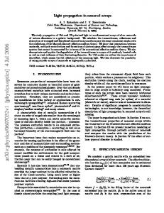
In order to observe morphologies by TEM, samples were scratched from Si wafers, sonicated in ethanol solution for 30 min and then dropped onto Cu grids. Compared with typical TEM image of SiO2 nanorods (Figure 2A), highly dispersed Au NPs (dark dots) with no aggregation loaded on SiO2 nanorods (grey color) are obviously observed on Figure 2B. The size and the dispersion of Au NPs can be seen clearly from the close observation of TEM image, as shown in Figure 2C. Particles size distribution is determined from more than 250 particles, and the results (Figure 2D) indicate the diameter of Au NPs is 2.3 nm ± 0.8 nm. It is obvious that the small size of Au NPs are kept and highly dispersed loaded on the surface of SiO2 nanorods even after being calcined at high temperature. However, gold particles Scheme 1. The formation process of well-defined Au/SiO2 nanorod arrays templated from aggregate severely if the sample with loaded PEO-b-PMA(Az) thin films. AuCl4− ions are calcined directly without VUV irradiation (see Supporting Information, Figure S2). This might be caused by fast reduction of gold not sputtered with a Pt/Au layer. Highly dispersed uniform Au during the calcination with no immobilization. NPs loaded on the surface of SiO2 nanorods are apparently visThe electronic structure of Au/SiO2 hybrid nanorod arrays at ible from the inset zoomed-in FE-SEM image in Figure 1D. different state is probed by X-ray photoelectron spectroscopy (XPS), as shown in Figure 3. Before VUV irradiation, the majority of the 4f photoemission on curve a is assigned to Au (III).[30] The AuCl4− ions are reduced to metallic gold after VUV irradiation, which is confirmed by the appearance of the core level at 84.9 eV corresponding to Au0 state (10 min, curve b). Furthermore, they are totally reduced by longer time VUV irradiation (60 min, curve c) or calcined at high temperature (550 °C, curve d), as evidenced by the disappearance of the core level feature of Au (III). Compared with curve c, the core level of the Au 4f7/2 binding energy shows slightly negative shift from 84.9 eV to 84.6 eV on curve d, and both are higher than the value of bulk Au (84.0 eV).[31] It is reported that the core level binding energy of Au increases with the decrease of particles size.[32] Therefore, it is suggested that after irradiated for 60 min, the resulting Au NPs might be smaller than 2.3 nm ± 0.8 nm, which is the average diameter of Au NPs after calcination obtained from TEM images (Figure 2B,C). Figure 4 shows the UV-vis spectra of BCP thin films and SiO2 nanorod arrays loaded with and without Au NPs. It can be seen that the BCP thin films (curve a) exhibit the absorption maxima at 245 nm, 326 nm, Figure 1. AFM height images (500 × 500 nm2) and FE-SEM images. A) AFM image of BCP and 430 nm, respectively.[21] After introducthin film (inset: FFT patterns), B) FE-SEM image (side-view, tilted 20°) of SiO2 nanorod arrays tion of the SiO2 gel, the hybrid films (curve (sputtered a Pt/Au layer with thickness of ≈2 nm for observation), C) AFM image of Au/SiO2/ BCP hybrid films after VUV irradiated for 10 min, and D) FE-SEM image (side-view, tilted 20°) b) exhibit the similar absorption spectrum, of Au/SiO2 nanorod arrays after VUV irradiated for 60 min and subsequently calcined with no and no absorption is observed on SiO2 for this wavelength scale (curve d). After being sputtered Pt/Au layers.
490
wileyonlinelibrary.com
© 2013 WILEY-VCH Verlag GmbH & Co. KGaA, Weinheim
Part. Part. Syst. Charact. 2013, 30, 489–493
www.particle-journal.com
www.MaterialsViews.com
COMMUNICATION
of Au NPs. With irradiation time extended to 60 min, the new peak is also observed. The peaks corresponding to BCP films decrease significantly, but they are still visible. This indicates, at this step, that BCP films are not removed completely, but the films disappear after subsequent calcination (curved f). Moreover, the peak of Au NPs shifts to ca. 510 nm on curve f. It is reported that the local refractive index around Au particles increases after the formation of silica shells.[33,34] Thus, it can be concluded from this blue shift that Au NPs are located on the surface other than coated inside of the SiO2 nanorods. The Au NPs are reduced in situ among the air voids of SiO2 xerogel by VUV irradiation, which is edged out of solid SiO2 nanorod surfaces during calcination. Furthermore, compared with curve c, the plasmon bind width in curve f becomes slightly sharper. It is reported that the plasmon width becomes broaden with the decrease of diameter of the gold NPs, especially for Au NPs smaller than 5 nm.[35,36] Hence, UV-vis results indicate that the size of Au NPs become slightly larger after calcination, which is consistent with the XPS results. In this fabrication process, the highly dispersed Au NPs loaded on SiO2 nanorods Figure 2. TEM images of A) SiO2 nanorods (A) and B,C) Au/SiO2 hybrid nanorods after calcina- benefit from two points. Firstly, the unique tion. D) Histogram of Au NPs loaded on the SiO2 nanorods. structure of SiO2 gels within PEO cylindrical domains immobilized the Au NPs on the surface of SiO2 nanorods. It is found that the resulting Au irradiated with VUV for 10 min, the absorption maxima at particles aggregated severely if the HAuCl4 aqueous solution 326 nm shows a 15 nm red shift. Simultaneously, there is is mixed with SiO2 sol and then dipped onto the BCP thin new peak at ca. 535 nm in curve c, indicating the formation films (Supporting Information Figure S3). Secondly, the step
Absorbance(a.u.)
c
Intensity (a.u.)
d
c b
e b a f d 400
500
600
700
Wavelength (nm)
a 300 92
90
88
86
84
82
80
Binding Energy (eV) Figure 3. Au 4f XPS spectra of SiO2 nanorod array loaded with AuCl4− ions irradiated with VUV for different times: a) 0 min, b) 10 min, c) 60 min, and d) 10 min irradiation and calcined at 550 °C for 6 h.
Part. Part. Syst. Charact. 2013, 30, 489–493
400
500
600
700
Wavelength (nm) Figure 4. UV-vis spectra of BCP thin films and SiO2 nanorod array with or without loaded with Au NPs. a) BCP thin films, b) SiO2/BCP hybrid films, c) Au/SiO2/BCP hybrid films, irradiated by VUV for 10 min, d) SiO2 nanorod array, e) Au/ SiO2/BCP hybrid films, irradiated by VUV for 60 min, and f) the sample in (e) calcined at 550 °C for 6 h.
© 2013 WILEY-VCH Verlag GmbH & Co. KGaA, Weinheim
wileyonlinelibrary.com
491
COMMUNICATION
www.particle-journal.com
www.MaterialsViews.com
Table 1. H2O2 formation from H2 and O2 using the catalysts prepared by different methods. Samplea)
Preparation method
Au particles size
Productivityb) [mmol H2O2 gcat−1 h−1]
Turnover frequency [h−1]
1
VUV 60 min, calcined 550 °C
2.3 nm Highly dispersed
0.10
750
2
Calcined 550 °C
Aggregated
ndc)
nd
3
SiO2 sol mixed with HAuCl4 solution as the precursor
Aggregated
nd
nd
a)0.5 g freshly prepared catalyst was used in every experiment. The reaction took place in a 100 mL flask containing 60 g deioned water at 298 K. The flow rates of H 2 and O2 were 18 mL/min, and 36 mL/min, respectively; b) The data were obtained after 1 h of reaction; c)nd means the H2O2 content is zero or too low to be determined −5 (


![Standing [111] gold nanotube to nanorod arrays via template growth](https://m.moam.info/img/260x300/standing-111-gold-nanotube-to-nanorod-arrays-via-t_5b7225e8097c474f718b4643.jpg)


