which, in most cases, is the use of brute-force optimization techniques to extract a large number of parameters. At the beginning, this technique first uses the ...
292
IEEE TRANSACTIONS ON MICROWAVE THEORY AND TECHNIQUES, VOL. 46, NO. 3, MARCH 1998
Small-Signal Modeling of HBT’s Using a Hybrid Optimization/Statistical Technique Hafedh Ghaddab, Fadhel M. Ghannouchi, Senior Member, IEEE, Fethi Choubani, and Ammar Bouallegue Abstract—A new formulation for extracting the elements of the small-signal equivalent-circuit model of heterojunction bipolar transistors (HBT’s) is proposed in this paper. This approach avoids the main problem of the conventional extraction methods which, in most cases, is the use of brute-force optimization techniques to extract a large number of parameters. At the beginning, this technique first uses the extraction procedure of a low-frequency HBT model. An analytical formulation that allows the reduction of the number of the unknowns of the lowfrequency model to only two, which have to be calculated using a suitable optimization technique, is described. This makes the optimization problem much easier to handle and increases the probability for converging to the actual elements of the model, thus avoiding the converging to spurious solutions. Secondly, in order to extend the model to higher frequencies, a statistical approach is proposed to extract parasitic extrinsic elements. An experimental validation is carried out on three HBT devices and satisfactory results are obtained up to 30 GHz. Index Terms—Heterojunction, modeling, semiconductor.
I. INTRODUCTION
M
OST OF THE conventional techniques to extract the small-signal heterostructure bipolar transistor (HBT) model elements are based in various degrees on numerical global optimization methods which aim to calculate the values of these elements by fitting calculated -parameters to measured ones [1], [2]. However, it is well known that the main drawback of these techniques is the convergence to nonphysical element values due to the multiple local solutions of the optimized objective function. In addition, the obtained solution for the element’s model may strongly depend on the initial value guests [3]. Several attempts to overcome this problem are to perform additional measurements on a set of extra test circuits to calculate the parasitic elements [4], [5]. The effects of the parasitics are then subtracted out from the measured -parameters to extract the intrinsic element values. Manuscript received December 31, 1996; revised December 10, 1997. This work was supported by the Natural Science and Engineering Research Council of Canada, by Ecole Sup´erieure des Postes et des T´el´ecommunications de Tunis, and by Ecole Nationale des Ing´enieurs de Tunis. H. Ghaddab is with the Laboratoire des syst´emes de T´el´ecomunications (L S. Telecoms), Ecole Nationale des Ing´enieurs de Tunis (ENIT), Tunisia, Ecole Sup´erieure des Postes et des T´el´ecomunications (ESPTT), Tunisia, and also with the D´epartement de g´enie e´ lectrique et de g´enie Informatique, Ecole Polytechnique de Montr´eal, Montreal, P.Q., Canada H3C 3A7. F. M. Ghannouchi is with the Laboratoire des syst`emes de T´el´ecomunications (L S. Telecoms), Tunisia, Ecole Nationale des Ing´enieurs de Tunis (ENIT), Tunisia, and Ecole Sup´erieure des Postes et des T´el´ecomunications (ESPTT), Tunisia. F. Choubani and A. Bouallegue are with the D´epartement de g´enie e´ lectrique et de g´enie Informatique, Ecole Polytechnique de Montr´eal, Montreal, P.Q., Canada H3C 3A7. Publisher Item Identifier S 0018-9480(98)02024-9.
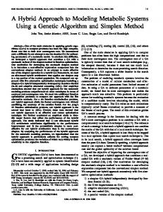
Fig. 1. Small-signal HBT model.
This leads to the elimination of any optimization process, but unfortunately, requires extra testing structures and additional measurements. In this paper, we propose a technique which divides the extraction problem into two parts. First, we consider a lowfrequency model in which capacitance and inductance parasitics are neglected [6]. Analytical expressions of all the model elements are written as functions of two new independent parameters. The elements of this model are extracted based on a two-parameter least square optimization technique. Secondly, in order to extend the validity of the model to microwave frequencies, the extrinsic inductances and capacitances are obtained using the variance of the intrinsic elements as a selection criteria. In fact, taking into account that the element values of the low-frequency equivalent circuit of the HBT are valid for high frequency, providing that extrinsic capacitances and inductances are added, the values of these extrinsic elements are determined by minimizing the variance of intrinsic elements over the operating frequency range as the extrinsic capacitance and inductance values are swept. In order to evaluate the accuracy and robustness of the proposed extraction approach, three different-size GaAs HBT devices are used. The two smallest ones are a single 3 m 5 m emitter–finger transistor (HBT1) and a single 2 m 20 m emitter–finger transistor (HBT2), while the largest one is a three 2 m 20 m emitter–finger HBT (HBT3). Satisfactory results are obtained up to 30 GHz. II. FORMULATION OF THE PROBLEM OF THE EXTRACTION TECHNIQUE A small-signal model of a HBT is shown in Fig. 1. This model includes both intrinsic and extrinsic elements. At low frequencies, the capacitances and inductances have insignif-
0018–9480/98$10.00 1998 IEEE
GHADDAB et al.: SMALL-SIGNAL MODELING OF HBT’S USING HYBRID OPTIMIZATION/STATISTICAL TECHNIQUE
icant effects on the behavior of the transistor, therefore, the HBT model can be reduced to a simplified one delimited by the dashed box, as shown in Fig. 1. This simplified model will be called the low-frequency model. For this low-frequency model, the -matrix can be calculated from the -parameters measured at low frequencies by conventional transformation equations. On the other hand, this -matrix can be expressed as a function of the intrinsic admittance matrix and extrinsic resistance matrix as shown below: (1) with (2)
293
approach consists of reducing the number of unknowns to two. These new parameters are defined as follows: (13) and (14) Firstly, to obtain an objective function depending only on these two parameters, an expression of the emitter resistance as a function of and will be found, as shown in the following section. Secondly, by substituting this expression into (13) and (14), the base and the collector resistances will be expressed as functions of these new variables. Then, the -matrix entries become functions only of and and measured -parameters as follows: (15)
is the intrinsic -parameter matrix which is related and to the intrinsic equivalent circuit elements by the following equations: (3) (4) (5) and (6) Equations (3)–(6) can be written in matrix format as follows:
where
(16) and, finally, the expressions of the intrinsic elements as and can be obtained using measured values functions of of -parameters and (3)–(6). At this step, all of the extrinsic and intrinsic elements are and . This formulation makes the functions only of optimization problem much easier to handle and increases the probability for converging to the physical solution of the model.
(7) where
and
III. LOW-FREQUENCY MODELING USING TWO-PARAMETER OPTIMIZATION TECHNIQUE
matrices are defined as (8)
and
is defined by
The first step of the solving approach is to find the exas function of and . pression of the emitter resistance Then, remaining series resistances and intrinsic parameters will and , as described below. be written as functions of To accomplish the first step, (16) is inserted into (11) and (12), yielding the following matrix equation: (17)
(9) with From (1), one can deduce (10) into its real and Substituting (7) into (10) and by splitting imaginary part , we end up with a real matrix equation system, relating the intrinsic elements to the extrinsic resistances and the measured -parameters as shown below: (11) (12)
(18) and (19) The left-to-right-hand side of (17) for the entries of the first row gives (20)
This set of equations forms a nonlinear system with eight independent variables. This system can be solved using iterative techniques or least square optimization techniques. However, in order to avoid the convergence to nonphysical solutions, both of these approaches require good starting initial guesses (which are difficult to obtain in practice). An alternative
and (21) By dividing (20) by (21), one can deduce (22)
294
IEEE TRANSACTIONS ON MICROWAVE THEORY AND TECHNIQUES, VOL. 46, NO. 3, MARCH 1998
EXTRINSIC RESISTANCES
Fig. 2. The emitter resistance
AND INTRINSIC
TABLE I ELEMENT VALUES
Re as function of a1 and a2 (for HBT1).
Equation (22) represents a third-order polynomial of , which can be solved analytically at any single frequency and and using the Cardanian formula for given values of [7]. Usually, only one among the three possible solutions of this equation is physically meaningful. The remaining have negative, very high, or even complex values. By sweeping and , one can generate a surface describing the dependency as function of and . It is found that strongly of and can be modeled by depends only on (23) where , , and are scalars. versus and In the case of HBT1, the variation of is shown in Fig. 2. The fitting of this surface with (23) gives , , and .
FOR THE
LOW-FREQUENCY MODEL
Fig. 3. Influence of a1 and a2 on gm (for HBT1).
Furthermore, as expected, it was found that dependency is almost constant over the frequency bandwidth. , and By substituting (23) into the expressions of into the intrinsic elements expressions all the low-frequency model elements can be written as functions only of and . Fig. 3 shows the evolution of as function of and for HBT1. At this step, low-frequency -parameters can be calculated as functions of and . The values of and can be obtained by performing a least-square optimization method to fit the measured and calculated -parameters. The solution obtained for and allows one to calculate all of the low-frequency model-element values. Table I shows the values of the intrinsic elements and the extrinsic resistances calculated for the three HBT’s at a frequency of 3 GHz and given bias points.
GHADDAB et al.: SMALL-SIGNAL MODELING OF HBT’S USING HYBRID OPTIMIZATION/STATISTICAL TECHNIQUE
Fig. 4. Frequency dependency of Cbe with Lb as parameter, the remaining extrinsic elements are fixed at values shown in Table II (for HBT1). (a) Lb = 0 pH. (b) Lb = 20 pH. (c) Lb = 40 pH. (d) Lb = 60 pH. (e) Lb = 80 pH. (f) Lb = 120 pH.
295
Fig. 6. Frequency dependency of Cbe with the optimum extrinsic parameters (for HBT1).
Fig. 5. Frequency dependency of gm with Lb as parameter, the remaining extrinsic elements are fixed at the values shown in Table II (for HBT2). (a) Lb = 0 pH. (b) Lb = 20 pH. (c) Lb = 40 pH. (d) Lb = 60 pH, (e) Lb = 80 pH. (f) Lb = 120 pH.
IV. EXTRACTION OF THE CAPACITANCE AND INDUCTANCE PARASITICS USING STATISTICAL TECHNIQUE At microwave frequencies, intrinsic elements will behave as functions of the extrinsic elements as well as frequency, depending on the fact that parasitic effects are more and more significant at higher frequencies. Fig. 4 shows the frequency and Fig. 5 shows the frequency characcharacteristics of teristics of , HBT1, and HBT2, respectively, while extrinsic elements are swept as parameters. To determine the values of the extrinsic elements, we take into account that the equivalent circuit has to be valid over the whole operating frequency range. Parasitic capacitances and inductances are determined by minimizing the error function that represents the variance of the intrinsic elements around the obtained low-frequency
Fig. 7. Algorithm of the extraction technique.
values and is given by the following equation: (24)
denotes the average over the frequency where range of the th intrinsic element varying as a function of frequency and extrinsic elements , and are lowfrequency intrinsic element values obtained previously.
296
IEEE TRANSACTIONS ON MICROWAVE THEORY AND TECHNIQUES, VOL. 46, NO. 3, MARCH 1998
Fig. 8. Comparison of measured (solid line) and calculated (dotted line) denotes the phase of Sij .
Fig. 9. Comparison of measured (solid line) and calculated (dotted line) denotes the phase of Sij .
Fig. 6 shows the frequency characteristic of at the optimal values of the extrinsic elements found above for HBT1. Moreover, in order to refine the model, one could use a global least square optimization technique with an objective function defined as (25)
S -parameters
(for HBT1).
a(Sij )
denotes the amplitude of
Sij
and
p(Sij )
S -parameters
(for HBT2).
a(Sij )
denotes the amplitude of
Sij
and
p(Sij )
where and are measured and calculated parameters, respectively. In this minimization only, parasitic capacitances and inductances are swept. The refined values are within approximately 5% of those obtained after satisfying the first criteria. Final values are given in Table II for the three HBT’s. Fig. 7 shows the algorithm implemented for the complete extraction technique. The code developed based on this algorithm has been used for modeling three different size HBT’s
GHADDAB et al.: SMALL-SIGNAL MODELING OF HBT’S USING HYBRID OPTIMIZATION/STATISTICAL TECHNIQUE
297
TABLE II EXTRINSIC CAPACITANCES
AND INDUCTANCES FOR THE
Fig. 10. Comparison of measured (solid line) and calculated (dotted line) denotes the phase of Sij .
manufactured at different foundries. The obtained values for the three HBT high-frequency models are given in Tables I and II. Comparison between measured and calculated -parameters are shown in Figs. 8–10 for a frequency range of 1–30 GHz. The good agreement between the measured and calculated parameters for the three different emitter-size HBT’s prove the validity of the extraction approach proposed in this paper. V. CONCLUSION A hybrid optimization/statistical technique for the HBT model extraction problem is proposed in this paper. This approach consists of expressing all of the low-frequency model elements as function of only two independent variables. An optimization technique is then performed to achieve the best fitting between the calculated and the measured -parameters. The values obtained for and are used to calculate all the
S -parameters
HIGH-FREQUENCY MODEL
(for HBT3).
a(Sij )
denotes the amplitude of
Sij
and
p(Sij )
extrinsic and intrinsic elements of the simplified low-frequency model. In order to extend the validity of the model to higher frequencies, parasitic capacitances and inductances are added. Their values are calculated by minimizing the variance of the intrinsic elements over the frequency range. The main advantages of this technique are as follows. 1) The subdivision of the model extraction approach into two main steps, low-frequency modeling and then highfrequency modeling, permits one to reduce the number of elements to be determined at each step; hence, increasing the probability of obtaining a more accurate and robust model. 2) The expressions of all the intrinsic and extrinsic lowfrequency elements as functions of only two parameters make the optimization problem much easier to handle
298
IEEE TRANSACTIONS ON MICROWAVE THEORY AND TECHNIQUES, VOL. 46, NO. 3, MARCH 1998
and avoids the convergence to nonphysical solutions. and as a ratio of resistances The choice of allows them to vary into a small range and, thus, the determination of their initial values becomes noncritical for the optimization. 3) The extraction of extrinsic capacitances and inductances is achieved without using any additional passive test structures or specific measurements on the active device. ACKNOWLEDGMENT The authors wish to thank Dr. R. Hajji for helpful discussions regarding this paper. REFERENCES [1] R. Hajji, A. B. Kouki, S. El-Rabaie, and F. M. Ghannouchi, “Systematic dc/small-signal/large-signal analysis of heterojunction bipolar transistors using a new consistent nonlinear model,” IEEE Trans. Microwave Theory Tech., vol. 44, pp. 233–241, Feb. 1996. [2] S. A. Maas and D. Tait, “Parameter-extraction method for heterojunction bipolar transistors,” IEEE Microwave Guided Wave Lett., vol. 2, pp. 502–554, 1992. [3] R. J. Trew, U. K. Mishra, and W. L. Pribble, “A parameter extraction technique for heterojunction bipolar transistors,” in IEEE MTT-S Int. Microwave Symp. Dig., 1989, pp. 897–900. [4] D. Costa, W. U. Liu, and J. S. Harris, “Direct extraction of the AlGaAs/GsAs heterojunction bipolar transistor small-signal equivalent circuit,” IEEE Trans. Electron Devices, vol. 38, pp. 2018–2024, Sept. 1991. [5] S. Lee, B. R. Ryum, and S. W. Kang, “A new parameter extraction technique for small-signal equivalent circuit of polysilicon emitter bipolar transistors,” IEEE Trans. Electron Devices, vol. 41, pp. 233–2038, Feb. 1994. [6] D. Wu and D. L. Miller, “Unique determination of AlGaAs/GaAs HBT’s small-signal equivalent parameters,” in IEEE GaAs IC Symp. Dig., 1993, pp. 259–262. [7] V. Sommer, “A new method to determine the source resistance of FET from measured S -parameters under active-bias conditions,” IEEE Trans. Microwave Theory Tech., vol. 43, pp. 504–510, Mar. 1995.
Hafedh Ghaddab was born in Monastir, Tunisia, in 1965. He received the electrical engineering degree and D.E.A. degree from Ecole Nationale d’Ing´enieurs de Tunis, Tunisia, in 1990 and 1993, respectively, and is currently working toward the Ph.D. degree in telecommunication engineering. In 1990, he joined the Ecole Sup´erieure des Postes et des T´el´ecommunications. His research interests include the characterization and modeling of microwave semiconductor active devices and specially HBT’s.
Fadhel M. Ghannouchi received the degree in physics/chemistry from the University of Tunis, Tunisia, in 1980, the B.Eng. degree in engineering physics, and the M.Eng. and Ph.D. degrees in electrical engineering from Ecole Polytechnique de Montreal, Montreal, P.Q., Canada, in 1983, 1984, and 1987, respectively. He is currently an Associate Professor in the Electrical Engineering Department, Ecole Polytechnique de Montreal, where he has been teaching electromagnetics and microwave theory and techniques since 1984. His research interests are microwave/millimeter-wave instrumentation and measurements. He has conducted several research projects that led to the design and construction of several six-port network analyzers over the 0.5–40-GHz range. He extended the six-port techniques from standard S -parameter measurements to large-signal (multiharmonic load–pull) and pulse characterization of microwave active devices. His other research interests are in the area of nonlinear modeling of microwave and millimeter-wave devices and to the control and calibration of phased-array antennas. Dr. Ghannouchi is a registered professional engineer in the province of Quebec, Canada. He is on the editorial board of IEEE TRANSACTIONS ON MICROWAVE THEORY AND TECHNIQUES and has served on the technical committees of several international conferences and symposiums and provides consulting services to a number of microwave companies.
Fethi Choubani (S’84–M’88–SM’93) was born in Mahdia, Tunisia, in 1961. He received the electrical engineering diploma from Ecole Nationale d’Ing´enieurs de Tunis, Tunisia, in 1987, and the docteur ing´enieur degree from Ecole Polytechnique de Toulouse, Toulouse, France, in 1993. Since 1993, he has been teaching applied electronics and microwave at Ecole Sup´erieure des Postes et des Telecommunications de Tunis, Tunisia. His research interests are focused on oscillators and their applications in electromagnetic sensors. He is also interested in EMC, nonlinear modeling, and microwave CAD.
Ammar Bouall`egue received the electrical engineering, and docteur ing´enieur degrees from ENSERG de Grenoble, Grenoble, France, in 1971 and 1975, respectively, and the Ph.D. degree from ENSEEIHT, INP de Toulouse, Toulouse, France, in 1984. In 1976, he joined the Ecole Nationale d’Ing´enieurs de Tunis (ENIT), Tunisia. From 1986 to 1994, he was Manager of the Electrical Department, ENIT, and from 1994 to 1996, he was Director at Ecole Sup´erieure des Postes et des T´el´ecommunications de Tunis, Tunisia. He is currently Manager of Laboratoire des Syst`emes de T´el´ecommunications (L.S.T´el´ecoms) at ENIT. His research interests include passive and active microwave structures and signal coding theory.