Virginia Power Electronics Center. Virginia Polytechnic Institute & State University. Blacksburg, Virginia 24061. Abstract - The small-signal modeling technique ...
Small-Signal Modeling of Series and Parallel Resonant Converters Eric X. Yang, Fred C. Lee, and Milan M. Jovanovic Virginia Power Electronics Center Virginia Polytechnic Institute & State University Blacksburg, Virginia 24061
Abstract - The small-signal modeling technique based on the extended describing functlon concept is applied to series-resonant converters (SRCs) and parallel-resonant converters (PRCs). The developed models include both frequency control and phase-shift control. The smallsignal equivalent circuit models are also derived and implemented in PSPICE. The models are in good agreement with measurement data.
1. INTRODUCTION The resonant converters have advantages for high power or high-frequency power conversion 11-71. When the switching frequency is below the resonant frequency, the active switches turn off at zero current condition, the natural commutation is very desirable for high power applications which employ BJTs, SCRs and GTOs. When the switching frequency is above the resonant frequency, zero voltage turn on of the active switches can be achieved and is ideal for MOSFETs. Due to the soft-switching characteristics, it is feasible to operate the converter at very high frequencies to get high power density. Two modulation techniques are usually employed. Instead of frequency modulation control, the resonant converters can also be regulated by phase-shift control [a-101,where the duty cycle is modulated and the switching frequency is kept constant. Small-signal analysis of the resonant converters has been reported [ll-141. A sample-data modeling approach was proposed in [l 11 as a systematic modeling method; it leads to a discrete-time model which is solved in the numericalform and is not easy to use in the compensator design. The closed form small-signal model [12]was obtained under high Q approximation. The model has limited accuracy and use. The small-signal model of series-resonant converters with diode conduction anglecontrol was proposed in [13].The model does not work for the more commonly used frequency control. Another modeling approach also based on discrete-time analysis was shown in [14]; the analytical model can predict high-frequency dynamic behavior. By sacrificing the high-frequency accuracy, the model can be transformed into continuous-time form, and the equivalent circuit model can be obtained. The problem of this method is that it can not achieve simplicity and accuracy at the same time.
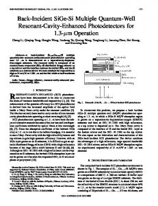
All of the small-signal analyses mentioned above based on the timedomain formulation, which either resorted in complex mathematical derivation, or numerical methods. A recently developed modeling technique employing an extended describing function concept [15-171combines the timedomain and frequencydomain analyses. A systematic small-signal modeling procedure based on this concept was discussed in detail in [17]. In this paperthe modeling method introduced in [17]is applied to the series-resonantconverters (SRCs) and parallel-resonant converters (PRCs). The continuous-time models were obtained in an analytical close-form and the equivalent circuit models are realized. The models include both frequency control and duty-cycle control (or commonly referred to as phase-shift control). The block diagram of the small-signal model is shown in Fig. 1. In Fig. 1, Gr and lo stand for small-signal perturbation of the line voltage and the output current respectively. fsN and d correspond to frequency control and duty-cycle control. The output variables include the perturbed average line current, L8, and the perturbed output voltage, Go. With the model, it is easy to obtain the commonly used small-signal transfer functions, such as control-to-output transfer function, line-to-output transfer function, input impedance, and output impedance. In Section II, the derivation of an SRC analytical small-signal model and circuit model is given. The PRC small-signal models are presented in Section 111. Section IV provides the experimental verification of these models.
Power Skage Model
Fig.1
A
A
fSN
d
7v+?
Block diagram of the small-signal model of resonant converters. The perturbation of the normalized switching frequency is defined as fSN =f,/F,,, where F, is the resonant frequency.
This work is supported by the VPEC Partnership Program and the Virginia Center for Innovative Technology (CIT).
7 85 0-7803-0485-3/92$3.00 0 1992 IEEE
II. SMALL-SIGNAL MODELINGOF SRC
B. Harmonic Approximation
In this section, the systematic small-signal modeling procedure proposed in [I 71 is applied to SRC. The step-by-step derivation of the small-signal models is illustrated.
A. Nonlinear State Equation The circuit diagram Of SRC is shown in Fig. 2. The active switch network generates a quasi-square wave voltage, v,, applied to the resonant tank. Under continuous tank current mode, the state equations of SRC are given by: di . L - + w , + v +sgn(i)v, = v , (la) df c--=l dv .
The interested output variables are the output voltage, v,, and
~
~
BY making this assumption, we have: i ( t )= i,(t) sin w,r + i,(t) c o s w,f v ( f )= v,(t)sinw,t
(YC)
2v
T
8
i
~
d
~
,
(h)
+ v,(t)cosw,f.
Notice that the envelope terms {is,ie,vs,vc}are slowly time varying, so the dynamic behavior of these terms can be investigated. The derivatives of i ( f )and v(r) are found to be:
_ d it -
(2
-- w,ic)sinwst
+(
2+wsis)wsm,t
(30)
C. Extended Describing Function
(Id)
By employing the extended describing concept [17], the nonlinear terms in (1) can be approximated either by the fundamental components terms or by the dc terms to give: (h) v,(t) = f , ( d ,vg)sin w,f
(le)
sgn(i)v, =f2(i,,i,,vC,)sinw,t
the averaged input current, ig, of the power stage:
i, =
by fundamental harmonics, and the output capacitor voltage can be approximated by dc component.
(1b)
df
v, = rtC(li I +io)+
The typical waveforms of the state variables are shown in Fig.
3,where the tank waveforms, i ( t )and v(t),can be approximated
where = rc 11 R . (In In this circuit, the output voltage is regulated either by modulating the switching frequency, w,, or controlling the duty cycle, d , while maintaining a constant switching frequency. The operating point is determined by { v g , i o , R , w s , d ) .
I
1
These U(. are called extended describingfunctions (EDFs). They are functions of the operating conditions and the harmonic coefficients of the state variables. The EDF terms can be calculated by making Fourier expansions of the nonlinearterms to give: a)}
4 .
T vM
I
Fig.2
Circuit diagram of SRC.
Fig.3
t
Typical waveforms of the state variables of an SRC.
(4fl
zeros, and set the dc bias of the external currant source I, = 0, then the steady-state solution can be obtained by solving (5) to give:
(4g 1
B I, = v*n,c-
a ' + p' a I, = v,n,ca'+ P' v, = Vt- a
f#,i,) =;sin(td)is, 2
' a
where
v, = -v,- a' B+ P'
i p = w
is the peak value of the tank current. D. Harmonic Balance With the small-signal modulation frequency lower than the switching frequency, by substituting (2-4) into ( l ) , and by equating the coefficients of dc. sine, and cosine terms respectively, we get:
+ B'
1 @qF
Ip= v,n,c
where
The steady-state solution provides the result of the dc analysis of SRC. For example, when the circuit has no loss and the duty ratio d is one, the voltage conversion ratio is given by: vo
M=-=
W R *
V# ~(1-n$Cy+(RsCR,)' . where
(7)
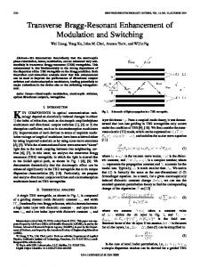
A result similarto (7) can be found in [7]. Thevoltageconversion ratio is the function of the load and the switching frequency, it is shown in Fig. 4, where
Equation (5) is a modulation equation. It is a nonlinear large-signal model of the SRC power stage. It is important that the inputs of (5),{vs,as,d,io}, are varying slower than the switching frequency, so it is readily perturbed and linearized at certain operating points. The corresponding output equations are:
I
0.e
M 04
0.2
E. Steady-State Solution: 0
Under steady-state conditions, the new state variables { i r , i c r ~ s , ~ , , ~are C f }not changing with time. Upper case letters
are used below to denote the steady-state values. For a given operating point {Vg,D,Qs,Io,fZ}, let the derivatives in (5) be
Fs/Fo
Fig. 4
787
Voltage conversion ratio of SRC based on steadystate solution of modulation equation.
F. Perturbation and Linearization Perturbing the large-signal model (5) around the operating point: LJ# = V, + Cr d =D + A i,=O+i,
a,=Q,+a,,
and making linearization underthe small-signal assumption give the model:
G =Q,C
dZ _ dr -Ai?+Bri
2 Is k =-I
y^ = CZ + Er?,
(9g 1
XI,
2IC k =--
(8b)
XI,
where ^
.
cC,c4lT ri = (C,, i,fSN, Lo).
(84
j = (Go, iy.
(8e 1
i? = (is, i,,
(8c)
R, = r, +R,- a ' a2+ P2
This analytical small-signal model has the standard form as the blockdiagram shown in Fig.1. The matrices are defined as:
'--R,
L -Z, L
A=
Z, -
L -R, L
-1 -
0
0
0
l
4-
c
ksrlC k,rfc -
-1
L -2, L
-G
O
C
G. Equivalent Circuit Model
0
0
0
'
-as
-
o -L -
C
c
0
L
0
-
-r
IC
,
According to (a), the small-signal model has a linear state equation description. By the inverse way of writing the state equation from a linear circuit, the small-signal equivalent circuit model can be synthesized from (8).as shown in Fig. 5.
'4-
5
L
L
The following controlled-sources are defined in the circuit model: C,, = kvCg + Edd (loa)
0
0
6, = Z,i, - 2 , C c J
(lob)
6, = Z j , + 2 , C
(10c)
B= 0
0
cyc
(Cfc
R Cfc
j s= G C , + J ~ ~ ~
0
(104
ic= G C, +J j s N ,
0 ' 0
0
CJ
This circuit model can be easily implemented in commonly used circuit simulation softwares, such as PSPICE.
+ Av ,
-
The model parameters are given as:
A
+ v, . E, = a,LI,
Fig.5
788
Equivalent small-signal circuit model of an SRC.
This is an unified power-stage model with standard form as shown in Fig. 1 . The model is time-continuous. The matrices are given as
111. SMALL-SIGNAL MODELING OF PRC Thecircuit diagram of PRC is shown in Fig. 6.The small-signal modeling procedure for PRC is same as that for SRC. The detailed derivation can be found in [17] for the lossless case. In this paper, only the final modeling results are presented.
1 , L
-2, -
With the following assumptions:
L
the resonant tank capacitor voltage v ( r ) is in continuous mode;
A=
1 C 0
the output inductor current iL,(t) is in continuous mode;
-
0
the tank state variables,
{i(l),v(t)},
are approximated by
their fundamental components; and the output filter state variables,
0
{iL,(t), vc,(t)},
are approxi-
k
mated by slowly varying dc terms; the small-signal model of a PRC is given by: -d f -Af+Bli dl
(lla)
j = C f + Eli,
Ed
0
0
0
-Js
0
0
0
-J c
0
0
0
0
-rfc -
B
(1lb)
E,
L L L o o Lz
where
0
0
o
C C
0
L/
-
r*
Cf,
f
0
C=
vgls:b I
03
Fig.6
E=(' 0 Jd 0
0 '
Given the PRC circuit parameters of: {L C ,Lp C/t rr, 1,)
e,
9
04
and the operating condition of: W,,R,,D,R,I, =Ol,
Circuit diagram of a PRC.
789
1
"')
IV. EXPERIMENTAL VERIFICATION
Partof the measurementdataaretakenfrom[2,11,12]toveridy the small-signal models derived in Section 111. The component values of an SRC are: C = 51nF L = 197p.H
Cf= 32p.F F, = 50.2KH~
Z, = 6 2 . m .
The component values of a PRC are: C=470nF L=36p.H
L, = 1.35mH
a J , = -w,C V ,-
P'
a2+
Fe = 38.7KHz
1
" a v, =; 4 v, sin(:*)
a=l+L2$C
Re
From the analytical model defined in (11,12), it is easy to synthesize the equivalent small-signal circuit model as shown in Fig. 7. In the Circuit model, the controlled-sources e,,, j,, and icare defined as: e,,, = kVV^,+ Edd (15a)
j^,
= g,,?,
= 8.75Q.
A full-bridge PRC is also built and measured to verify the dutycycle-to-output transfer function and output impedance of the small-signal model. The circuit parameters are: C = 98.4nF L = 101.7w
2
R, =-R 8
jt= gC ,,
z,
The control-to-output transfer functions of the SRC and the PRC, when switching frequency is modulated, are shown in Figs. 8 and 9 respectively, for different operating conditions. The line-to-outputtransfer function of SRC is shown in Fig. 10. The input impedance of the SRC is shown in Fig. 11.
where =-
Cr = 32p.F
- 2k Lf
i^ +J j , ,
(156)
- 2k I4 i Jj;,
(156)
L/= 1 . w
c/=45.4pF
F, = 50.3KHZ
Z, = 32.1R.
The output-impedance is shown in Fig. 12. The dutycycleto-output transfer function is shown in Fig. 13.
As can be seen, all of the predicted small-signal transfer functions are in good agreement with the measurement data. Due to the symmetrical nature of the resonant converters, the small-signal models allow the modulation frequency to sweep
Thiscircuit model can be easily implementedin commonly used computer simulation softwares, such as PSPICE.
from dc up to the switching frequency as discussed in [l 1, 171. The dynamics of the resonant converters include both the low-frequency behavior and the high-frequency behavior. The low-frequency dynamics are determined by the output filter whose damping factor is related with both the load resistance and the ac resistance of resonant tank. The high-frequency dynamics is around the so called "beat frequency," the difference between the switching frequency and the resonant frequency (11,121. These ac behaviors can be correctly predicted by the models derived in this paper. One of the advantages of this modeling technique is that it is not depend on the high 0 assumption, and models are as accurate as the numerical
Fig. 7
sample-data models in [ l 11.
Small-signal equivalent circuit model of PRC.
790
1-
l:b
-10 -20
\
I
10k
ark
Openllng Pc
0 Omuwnmmnt
O p = 2 P FeA---.-
Opeming Point -1.5
F&Fo=OI D=1
do
20-
300
100
lk
3k
Frequency IdB)
0 0
messurommt
a p n r i n g mint 0-3.0
FWFOrl.3
hl
60
-m
IS
300
100
30
3k
1k
lolc
3QLSOk
Froquoncy (Hz)
Fig. 8
SRC Control-to-Output Transfer Functions. The
Fig. 9
PRC Control-to-Output Transfer Functions. The switching frequency is the control variable. Measurement data are taken from [l 1 , 121.
switching frequency is the control variable. Measurement data are taken from [l 1 , 121.
v 0 ; : -60
-100
-
Operating Point 0.14
-120
90
FdFolO.6
D-1
-270
-10 40
100
300
3k
lk
IMC
ZOk 4Ok
Froquoncy (Hz)
Fig. 10
SRC Line-to-Output Transfer Functions. Mea-
Fig. 11
SRC Input-Impedance. Measurement data are taken from [2].
surement data are taken from [ l 1, 121.
-
pedlctlon
-20
Oporatlng Pdnt
1
4
Opr1.17 Fanrl.24 Dr0.76
200
-40f-c -60 -
-60
Ph..
I
1
100
200
.
I
....
500
I
1K
1
ZK
.
.
I
.
.
5K
.
,
10K
I
ZOK
i .,lo
PRC Output-Impedance.
FI/Fo=1.18 Lk0.70
-270
Bo
40K60K
100
Frequency (Hr)
Fig. 12
-1.33
200
500
1K
2K
Fmqu-y
Fig. 13
791
SK
10K
ZOK
40K
(mi
PRC Duty-Cycle-to-Output Transfer Function.
F. S. Tsai, P. Materu, and F. C. Lee, "Constant frequency, clamped moderesonantconverters," in IEEEPower Electronics Specialists' Conf. Rec. 1987, pp. 557 - 566. F. S. Tsai. and F. C. Lee, "Complete dc characterization of constant frequency clamped mode series resonantconverter," in Power Electronics Specialists' Conf. Rec. 1988, pp. 987 996. F. S. Tsai, Y. Chin, and F. C. Lee, "State-plane analysis of a constant-frequency clamped-mode parallel-resonant converter,' IEEETrans. on Power Electron., Vol. 3, no. 3, pp. 364-378, 1988. V. Vorperian and S. Cuk, "Small-signal analysis of resonant converters,' in IEEE Power Electronics Specialists' Conf. Rec. 1983, pp. 269-282. V. Vorperian, "High-Q approximation in the small-signal analysis of resonant converters," in IEEE Power Electronics Spe cialists' Conf. Rec. 1985, pp. 705-715. R. J. King and T. A. Stuart, "Small-signal model of the series resonant converter," IEEE Trans. Aerosp. Electron. Syst., Vol. 21, no. 3, pp. 301-319, 1985. A. Witulski and R. Erickson. "Small-signalac equivalentcircuit modeling of the series resonant converter," in IEEE Power ElectronicsSpecialists' Conf. Rec. 1987. pp. 693-704. S. Sanders, J. Noworolski. X. Liu, and G. Verghese, "Generalizedaveragingmethodfor powerconversioncircuits," in IEEE Power ElectronicsSpecialists' Conf. Rec., 1989, pp.273-290. C. T. Rim, and G. H. Cho, "Phasor transformation and its application to the ddac analysis of frequency phase-controlled series resonant converters (SRC)," IEEE Trans. Power Electron., Vo1.5. no.2, pp.201-211, 1990. E. X. Yang, F. C. Lee, and M. M. Jovanovic, "Small-signal modeling of power electronic circuits by extended describing function concept," Proc. VPEC Seminar 1991, pp. 167-178.
V. CONCLUSION In this paper, the small-signal modeling technique based on the extended describing function concept is applied to the SRCs and PRCs. The continuous-time small-signal models are derived in the analytical forms without high Q assumption. The equivalent circuit models are also synthesized to facilitate analysis using popular circuit analysis program such as PSPICE. The models are in good agreement with measurement data. The high frequency dynamics of resonant converters around the beat-frequency can be accurately modeled. These simple analytical models can be employed in the control loop design of resonant converters.
REFERENCE 111
121 131
141
151
161
[71
V. Vorperian and S. Cuk, "A complete dc analysis of the series
resonant converter," in IEEE Power Electronics Specialists' Conf. Rec. 1982, pp. 85-100. V. Vorperian, "Analysis of resonant converters," Ph.D Dissertation, California Inst. of Technol., Pasadena, May 1984. R. L. Steigerwald, "High-frequency resonant transistor dc-dc converters," IEEE Trans. Ind. Electron., Vol. 31, no. 2, pp. 181-191, 1984. R. Oruganti and F. C. Lee, "Resonant power processors, Part I - State plane analysis,' IEEE Trans. Ind. Appl., Vol. 21, no. 6, pp. 1453-1460, 1985. A. Witulski and R. Erickson, "Steady-state analysis of series resonant converter," IEEE Trans. Aerosp. Electron. Syst., Vol. 21, no. 6, pp. 791-799. 1985. S. Johnson and R. Erickson, 'Steady-state analysis and design of the parallel resonant converter," in IEEE Power Electronics Specialists' Conf. Rec. 1986, pp. 154-156. R. L. Steigerwald, "A comparison of half-bridge resonant converter topologies," IEEE Trans. Power Electron., Vol. 3, no. 2, pp. 174-182, 1988.
792