57
ISSN 1392 - 1207. MECHANIKA. 2014 Volume 20(1): 57-63
Solution of the boundary layer flow of various nanofluids over a moving semi-infinite plate using HPM N. Dalir*, S.S. Nourazar** *Department of Mechanical Engineering, Amirkabir University of Technology, Tehran, Iran, E-mail:
[email protected] **Department of Mechanical Engineering, Amirkabir University of Technology, Tehran, Iran, E-mail:
[email protected] http://dx.doi.org/10.5755/j01.mech.20.1.3406
1. Introduction The performance of thermal systems is subjected to a primary limitation due to the low thermal conductivity of conventional heat transfer fluids. In order to improve the thermal conductivity, nanoscale particles being dispersed in a base fluid, known as nanofluid, are used. Thus nanofluids are suspensions of nanoparticles in fluids. Nanofluids offer considerable advantages over conventional heat transfer fluids. Compared to pure fluids, they enhance thermal and transport properties considerably. Wherever heat transfer enhancement is crucial such as in nuclear reactors, transportation and electronics, nanofluids are usable. They can enhance thermal conductivity of the base fluid enormously. Nanofluids are also very stable and have no additional problems such as non-Newtonian behavior, the reason being the tiny size of nanoparticles. The research on nanofluids began over a decade ago, by focusing on measuring and modeling their effective thermal conductivity and viscosity. Choi et al. [1] added a small amount of nanoparticles to conventional heat transfer fluids and observed the increase of thermal conductivity. Das [2] presented a numerical investigation on the convective heat transfer performance of nanofluids over a permeable stretching surface in the presence of partial slip, thermal buoyancy and temperature dependent internal heat generation or absorption. Makinde and Aziz [3] studied numerically the boundary layer flow induced in a nanofluid due to a linearly stretching sheet with a convective boundary condition at the sheet surface. Kandasamy et al. [4] solved numerically the problem of laminar fluid flow which results from the stretching of a vertical surface with variable stream conditions in a nanofluid. They used a model for the nanofluid which incorporates the effects of Brownian motion and thermo-phoresis in the presence of magnetic field. Anwar et al. [5] investigated theoretically the problem of free convection boundary layer flow of nanofluids over a non-linear stretching sheet, incorporating the effects of buoyancy parameter, the solutal buoyancy parameter and the power law velocity parameter. Boundary-layer flow problem over a moving or fixed flat plate is a classical problem, which has been investigated by many researchers, for example Bachok et al. [6] studied the steady-state boundary-layer flow of a nanofluid over a moving semi-infinite flat plate in a uniform free stream, and found that dual solutions exist when the plate and the free stream move in the opposite directions. Bachok et al. [7] investigated the problem of a uniform free stream of nanofluid parallel to a fixed or moving flat plate. They solved the problem using the shooting method. Ahmad et al. [8] solved the Blasius and Sakiadis problems in nan-
ofluids and concluded that the inclusion of nanoparticles into the base fluid had resulted in an increase of the skin friction and heat transfer coefficients. In the present paper, the two-dimensional steadystate boundary layer flow of nanofluids over an impermeable semi-infinite moving flat horizontal plate embedded in the water-based nanofluid is studied. It is assumed that the flat plate moves with a constant velocity. The governing equations, i.e. mass and momentum conservation equations, are transformed using the similarity transformations to a nonlinear ordinary differential equation (ODE), and then the resulting ODE is solved using the homotopy perturbation method (HPM). Six types of nanoparticles, i.e., copper (Cu), alumina (Al2O3), titania (TiO2), copper oxide (CuO), silver (Ag), and silicon (SiO2) in the water based fluid with Pr = 6.2 are considered. The velocity and stream function profiles are plotted for various nanoparticles and for various values of the nanoparticle volume fraction. The effect of the nanoparticle volume fraction on the flow characteristics, and mainly on the local skin friction coefficient, is investigated. 2. Mathematical formulation The steady-state two-dimensional laminar boundary layer flow over a continuously moving flat horizontal plate embedded in a water-based nanofluid is considered. The nanofluid can contain each of six types of nanoparticles including Cu, Al2O3, TiO2, CuO, Ag, and SiO2. It is assumed that the plate has a constant velocity. A uniform spherical size and shape is assumed for the nanoparticles. It is also assumed that the base fluid and the nanoparticles are in the thermal equilibrium, and no velocity slip occurs between the base fluid and the nanoparticles [9]. Considering these assumptions, the laminar boundary layer equations of mass and momentum conservation are as follows:
∂u ∂v + =0; ∂x ∂y u
∂u ∂ u μnf ∂ 2 u +v = . ∂x ∂ y ρ nf ∂ y 2
(1)
(2)
The boundary conditions for the fluid velocity are as follows: u = U w , v = 0 at y = 0;⎫ ⎬ u → 0 as y → ∞ . ⎭
(3)
in which Uw is the plate velocity which is constant, and u
58 and v are the velocity components in x- and y-directions, respectively. ρnf is the density of the nanofluid, and μnf is the viscosity of the nanofluid, which are given by the following relations [10]: ρ nf = (1 − ϕ ) ρ f + ϕ ρ s , μnf =
μf
(1 − ϕ )
2.5
,
(4)
where φ is the nanoparticle volume fraction, and ρf and ρs are the densities of fluid and solid fractions, respectively. The dimensionless similarity variable and the dimensionless stream-function used to transform the governing equations to an ordinary differential equation are defined as: η=
1 ψ ( x, y ) y 2 Rex , f (η ) = , 1 x 2 (U wυ f x )
(5)
where Rex = Uwx / υf is the local Reynolds number, in which υf is the kinematic viscosity of the base fluid (water). ψ (x,y) is the stream function which identically satisfies Eq. (1) and is defined as u = dψ / dy, v = - dψ / dx. By the use of the similarity parameters (5), the boundary layer momentum Eq. (2) and the boundary conditions (3) transform to the following forms: f ′′′ +
ρ ⎞ 1 2.5 ⎛ (1 − ϕ ) ⎜⎜1 − ϕ + ϕ s ⎟⎟ ff ′′ = 0 ; ρf ⎠ 2 ⎝
f ( 0 ) = 0, f ′ ( 0 ) = 1, f ′ ( ∞ ) = 0 .
(6) (7)
In Eqs. (6) and (7), prime denotes differentiation with respect to η. The significant quantity is the local skin friction coefficient Cf,x defined as Cf ,x = τw / ρf Uw2, in which the plate surface shear stress is given as τw = μnf (du/dy)y=0. Use of the similarity parameters (5) gives [11]: C f , x Re
0.5 x
=
f ′′ ( 0 )
(1 − ϕ )
2.5
.
(8)
3. Solution by homotopy perturbation method (HPM) Using HPM [12], the original nonlinear ODE (which cannot be solved easily) is divided into some linear ODEs (which are solved easily in a recursive manner by mathematical symbolic software such as Mathematica or Maple). At first, the governing ODE (6) and the boundary conditions (7) are written as: u ′′′ +
ρ ⎞ 1 2. 5 ⎛ (1 − ϕ ) ⎜⎜1 − ϕ + ϕ s ⎟⎟ uu ′′ = 0 ; ρf ⎠ 2 ⎝
u ( 0 ) = 0, u ′ ( 0 ) = 1, u ′ ( ∞ ) = 0 .
(9) (10)
Then, a homotopy is constructed in the following form:
u ′′′ − α 2 u ′ + ⎛1 ⎞ ρ ⎞ 2.5 ⎛ + p ⎜ (1 − ϕ ) ⎜1 − ϕ + ϕ s ⎟ uu ′′ + α 2 u ′ ⎟ = 0 . ⎜ ⎟ ⎜2 ⎟ ρf ⎠ ⎝ ⎝ ⎠
(11)
According to HPM, the following serious in terms of powers of p is substituted in Eq. (11):
u = u0 + pu1 + p 2 u2 +L
(12)
After some algebraic manipulation, equating the identical powers of p to zero gives: p0: u0′′′ − α 2 u0′ = 0 ; u0 ( 0 ) = 0; u0′ ( 0 ) = 1; u0′ ( ∞ ) = 0 ; (13) ⎫ ⎪ ⎪ ρs ⎞ 1 2.5 ⎛ 2 + (1 − ϕ ) ⎜1 − ϕ + ϕ ⎟ u0 u0′′ + α u0′ = 0;⎬ ⎜ ⎟ ρf ⎠ 2 ⎪ ⎝ ⎪ u1 ( 0 ) = 0; u1′ ( 0 ) = 0; u1′ ( ∞ ) = 0; ⎭
(14)
ρ ⎞ ⎫ 1 2.5 ⎛ (1 − ϕ ) ⎜⎜1 − ϕ + ϕ s ⎟⎟ ×⎪ 2 ρf ⎠ ⎪ ⎝ ⎬ 2 × ( u0 u1′′ + u1u0′′ ) + α u1′ = 0; ⎪ ⎪ u2 ( 0 ) = 0; u2′ ( 0 ) = 0; u2′ ( ∞ ) = 0. ⎭
(15)
2 p1: u1′′′− α u1′ +
p2: u2′′′ − α 2 u2′ +
Eq. (13) for p0 has the following solution: u0 (η ) =
1 (1 − exp ( −αη ) ) . α
(16)
Here α is a constant which is further to be determined. If solution (16) for u0 is substituted in the equation for p1, Eq. (14), it will become as: ⎡1 ⎤ ρ ⎞ 2 .5 ⎛ u1′′′− α 2 u1′ = ⎢ (1 − ϕ ) ⎜ 1 − ϕ + ϕ s ⎟ − α 2 ⎥ × ⎜ ⎟ ρf ⎠ ⎢⎣ 2 ⎥⎦ ⎝ × exp ( −αη ) −
ρ ⎞ 1 2 .5 ⎛ (1 − ϕ ) ⎜⎜1 − ϕ + ϕ s ⎟⎟ exp ( −2αη ) . 2 ρf ⎠ ⎝
(17)
Eq. (17) for u1 can be solved in an unbounded domain under the boundary conditions u1(0) = 0, u’1(0) = 0, u’1(∞) = 0 (as it is shown in the Appendix) [13], which gives u1 as: Ω ⎞ Ω ⎛ 1 u1 (η ) = ⎜ − 3 ⎟+ exp ( −2αη ) + 2 α 6 12 α α3 ⎝ ⎠ Ω ⎞ ⎛ 1 +⎜− + exp ( −αη ) . 3 ⎟ ⎝ 2α 12α ⎠
(18)
in which α = (Ω / 2)0.5 and Ω = (1 – φ)2.5 [1 – φ + φ (ρs / ρf)]. It should be noted that α can be α = ± (Ω / 2)0.5, but here as α is demanded to be positive (α > 0), therefore α = (Ω/2)0.5. Thus the first-order approximate semianalytical solution f(η) = u(η) = u0(η)+u1(η) becomes as:
59
Ω ⎞ Ω ⎛ 3 f (η ) = ⎜ exp ( −2αη ) + − 3 ⎟+ 3 ⎝ 2α 6α ⎠ 12α Ω ⎞ ⎛ 3 +⎜− + ⎟ exp ( −αη ) . 2 α 12 α3 ⎠ ⎝
(19)
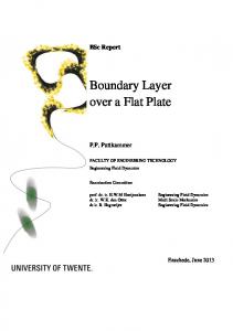
Comparison of Fig. 1 with the nanoparticles densities in table 1 makes it clear that the nanoparticles with higher density result in higher magnitudes of f”(0) and the nanoparticles with lower density result in lower f”(0) magnitudes. -0.2
According to Eq. (19), the dimensionless plate surface shear stress is as:
-0.3
(20)
4. Results and discussion A small computer code in the symbolic software Mathematica is written and HPM solutions to the governing ordinary differential Eq. (6) with the boundary conditions (7) are obtained. The solutions are shown in tables and diagrams. In Table 1 the density of water and nanoparticles used in the present study are given. Table 2 gives the HPM solution values of the dimensionless fluid velocity gradient at the plate surface α = f”(0) for Cu-water, Al2O3-water, TiO2-water, CuOwater, Ag-water and SiO2-water working fluids for various values of the nanoparticle volume fraction φ. It can be seen that the values of f”(0) are equal for Cu-water, Al2O3water, TiO2-water, CuO-water, Ag-water and SiO2-water working fluids in zero nanoparticle volume fraction (i.e., φ = 0). This is logical because the governing Eq. (6) reduces to f’” + 0.5ff” = 0 in φ = 0, which is the governing equation of boundary layer flow of a pure fluid. Therefore the semi-analytical results for f”(0) in φ = 0 are not changed by the type of nanoparticle used. It can also be seen that when the solid nanoparticle volume fraction φ increases, the magnitude of f”(0) increases slightly in Cuwater, CuO-water and Ag-water working fluids, but it decreases slightly in Al2O3-water, TiO2-water and SiO2-water working fluids. Table 3 compares HPM solution and numerical solution [7] values of the local skin friction coefficient (Cf,x Rex0.5 = f”(0) / (1 – φ)2.5) for Cu-water, Al2O3-water, TiO2water, CuO-water, Ag-water and SiO2-water working fluids for various values of the nanoparticle volume fraction φ (0 ≤ φ ≤ 0.2). It can be seen that the HPM solutions agree within 2% error with the numerical solutions obtained using a shooting method. HPM results for Cu-water working fluid are also compared with the experimental data [8] of the local skin friction coefficient in table 3, where a good agreement within 1% error is observed. It is also seen that when φ increases, the local skin friction coefficient magnitude increases. It is also observed that when φ = 0 the local skin friction coefficient (Cf,x Rex0.5) values are equal for all the working fluids. The reason is that when φ = 0 the nanofluid boundary layer flow problem reduces to the regular fluid boundary layer problem, and thus the nanoparticle type does not alter the values of skin friction coefficient. Fig. 1 presents the variations of f”(0) with φ for various nanoparticles (i.e., Cu, Al2O3, TiO2, CuO, Ag and SiO2) using HPM solution from Table 2. It is seen that with the increase of φ the magnitude of f”(0) increases for Ag-water, Cu-water and CuO-water working fluids, but the magnitude of f”(0) decreases for TiO2-water, Al2O3-water and SiO2-water working fluids with the increase of φ.
fηη(0)
3 5Ω f ′′ ( 0 ) = − α + 2 12α
Cu Al2O3 TiO2 CuO Ag SiO2
-0.4
-0.5
-0.6
-0.7
0
0.05
0.1
0.15
0.2
ϕ Fig. 1 Variation of the dimensionless fluid velocity
gradient at the plate surface f”(0) with φ for various nanoparticles using HPM
Fig. 2 demonstrates the variations of dimensionless skin friction group (Cf,xRex0.5) with the nanoparticle volume fraction φ for various nanoparticles using HPM solution from table 3. It can be seen that for all types of nanoparticles (Ag, Cu, CuO, TiO2, Al2O3 and SiO2) the dimensionless skin friction group magnitude at the plate surface Cf,x Rex0.5 increases when φ increases. Thus it can be said that the addition of any type of nanoparticle to a regular fluid enhances the skin friction. It can also be observed that a higher nanoparticle volume fraction results in a higher dimensionless skin friction group. Thus the addition of more and more amounts of nanoparticles of any type to a fluid (up to φ ≤ 0.2) causes the skin friction boost. Nevertheless, as it is clear from Fig. 2, the amount of increase in Cf,x Rex0.5 by the addition of nanoparticles to the regular fluid is not the same for all types of nanoparticles. For instance, for Ag nanoparticles the increase of Cf,x Rex0.5 is higher compared to all the other nanoparticle types, and for the SiO2 nanoparticles it is lower compared to the other nanoparticle types. Here, similar to Fig. 2, the trend of Cf,x Rex0.5 increase is proportional to the density of nanoparticles. The variations of local skin friction coefficient (Cf,x) with the local Reynolds number (Rex) for various values of φ for Cu-water working fluid is plotted in Fig. 3 using HPM solution from Table 3. The horizontal axis gives the Re number values in the laminar boundary layer flow range (Rex ≤ 105). It is seen that the Cf,x magnitude decreases with the increase of the Re number, and lower φ values result in lower Cf,x’s. Thus when the situation favors the use of nanofluid along with lower skin friction coefficient, lower nanoparticle volume fractions with higher Reynolds numbers are ideal. Fig. 4 is the curve for the local skin friction coefficient (Cf,x) as a function of the Reynolds number for various nanoparticles. As it can be seen, the higher the Reyn-
60 Table 1
Density of water and nanoparticles [10] Density ρ, kg/m3
Fluid Phase (water) 997.1
Cu 8933
Al2O3 3970
TiO2 4250
CuO 6500
Ag 10500
SiO2 2670 Table 2
Values of α = f”(0) for various working fluids using HPM φ 0.0 0.1 0.2
Cu-water working fluid -0.461410 -0.538417 -0.557023
Al2O3-water working fluid -0.461410 -0.455451 -0.444905
TiO2-water working fluid -0.461410 -0.460196 -0.447039
φ 0.0 0.1 0.2
CuO-water working fluid -0.461410 -0.514793 -0.517323
Ag-water working fluid -0.461410 -0.577509 -0.608019
SiO2-water working fluid -0.461410 -0.446562 -0.412185 Table 3
0.5
Values of the local skin friction coefficient (Cf,x Rex ) for various working fluids using HPM, numerical solution and experimental data
φ 0.0 0.1 0.2
φ 0.0 0.1 0.2
Cu-water working fluid Present Numerical Experimenresults solution [7] tal data [8] -0.461410 -0.4438 -0.455 -0.700670 -0.6784 -0.691 -0.973080 -0.9442 -0.961
Al2O3-water working fluid Present reNumerical sults solution [7] -0.461410 -0.4438 -0.592702 -0.5767 -0.777218 -0.7410
TiO2-water working fluid Present Numerical results solution [7] -0.461410 -0.4438 -0.598875 -0.5830 -0.780946 -0.7540
CuO-water working fluid Present Numerical Experimenresults solution [7] tal data [8] -0.461410 -0.4438 -0.455 -0.669925 -0.903726
Ag-water working fluid Present reNumerical sults solution [7] -0.461410 -0.4438 -0.751541 -1.062170
SiO2-water working fluid Present Numerical results solution [7] -0.461410 -0.4438 -0.581133 -0.720057
1
olds number, the lower the skin friction coefficient values. It can also be seen that the Ag nanoparticles give the highest Cf,x’s and the SiO2 nanoparticles give the lowest values of the Cf,x.
0.9
0.7
-0.2
-0.4
Cf,xRe0.5 x
-0.5 -0.6
|Cf,x|
Cu Al2O3 TiO2 CuO Ag SiO2
-0.3
0.6 0.5 0.4 0.3 0.2 0.1
-0.7
0 0 10
-0.8
101
102
103
104
105
Rex
-0.9 -1 -1.1
ϕ=0.0 ϕ=0.1 ϕ=0.2
0.8
0
0.05
0.1
0.15
0.2
ϕ Fig. 2 Variation of the dimensionless skin friction group (Cf,x Rex0.5) with φ for various nanoparticles using HPM
Fig. 3 Variation of the local skin friction coefficient (|Cf,x|) with Reynolds number (Rex) for various values of φ for Cu-water working fluid using HPM Fig. 5 depicts the velocity profiles f’(η) for some values of φ (φ = 0, 0.1, 0.2) for Cu-water working fluid using HPM solution. It can be observed that the velocity profiles are steeper for the nanofluid cases (i.e., φ = 0.1 and 0.2). Thus the velocity boundary layer is considerably
61 thinner for the nanofluid cases (i.e., φ = 0.1 and 0.2) compared to regular fluid case (φ = 0).
function values decrease when the nanoparticle volume fraction φ increases.
0.8
1
0.4
0.8 0.7
fη(η)
0.6
|Cf,x|
0.9
Cu Al2O3 TiO2 CuO Ag SiO2
0.6 0.5 Cu Al2O3 TiO2 CuO Ag SiO2
0.4 0.3
0.2
0.2 0.1
0 0 10
101
102
103
104
0
105
0
0.2 0.4 0.6 0.8
Rex Fig. 4 Variation of the local skin friction coefficient (|Cf,x|) with Reynolds number (Rex) for various nanoparticles when φ = 0.1
ϕ=0.0 ϕ=0.1 ϕ=0.2
ϕ=0.0 ϕ=0.1 ϕ=0.2
1
f(η)
fη(η)
2
1.4 1.2
0.8
1.2 1.4 1.6 1.8
Fig. 6 Velocity profiles f’(η) for various nanoparticles when φ =0.1 using HPM
1.2 1
1
η
0.6
0.8 0.6 0.4
0.4
0.2 0.2
0 0
0.2 0.4 0.6 0.8
1
η
1.2 1.4 1.6 1.8
0
0.2 0.4 0.6 0.8
2
Fig. 5 Velocity profiles f’(η) for some values of φ for Cuwater working fluid using HPM In Fig. 6 the velocity profiles f’(η) for various nanoparticles (Cu, Al2O3, TiO2, CuO, Ag and SiO2) in φ = 0.1 are demonstrated using HPM solution of the present paper. It can be seen that the boundary layer velocity profiles are affected by the types of nanoparticles used in nanofluids. It is also observable that the steepest velocity profile is for Ag nanoparticles, and therefore the velocity boundary layer has the lowest thickness for Ag nanoparticles. With regard to the steepness of the velocity profile, the nanoparticle types Cu, CuO, TiO2, Al2O3 and SiO2 stand on the next steps. Thus SiO2 nanoparticles generate the thickest velocity boundary layer. It is worth mentioning that the nanofluid boundary layer thickness is inversely proportional to the density of nanoparticles used in the working fluid. Fig. 7 shows the stream-function profiles f (η) for some values of the nanoparticle volume fraction φ for Cuwater working fluid using HPM. Here again, thicker boundary layer can be observed for the regular fluid (φ = 0) compared to the nanofluid cases (φ = 0.1 and 0.2). It can also be seen from the HPM results that the stream-
1
η
1.2 1.4 1.6 1.8
2
Fig. 7 Stream-function profiles f (η) for some values of φ for Cu-water working fluid using HPM 1.4 1.2 1
f(η)
0
0.8 0.6
Cu Al2O3 TiO2 CuO Ag SiO2
0.4 0.2 0
0
0.2 0.4 0.6 0.8
1
η
1.2 1.4 1.6 1.8
2
Fig. 8 Stream-function profiles f (η) for various nanoparticles when φ = 0.1 using HPM Finally, the stream-function profiles f (η) for various nanoparticles in φ = 0.1 using the HPM solution are
62 shown in Fig. 8. It is seen that the highest stream-function values are for the Ag nanoparticles and the lowest streamfunction values are for the SiO2 nanoparticles. With regard to the stream-function values, the other types of nanoparticles fall with the order of Cu, CuO, TiO2 and Al2O3 between Ag and SiO2 nanoparticles. It should be said that this order of variation for values of the stream-function is seen to be inversely proportional to the densities of relevant nanoparticles. 5. Conclusions The two-dimensional boundary layer flow of nanofluids over an impermeable consciously moving horizontal plate is studied. The continuity and momentum conservation equations are transformed by the similarity method to a nonlinear ordinary differential equation which is solved using the homotopy perturbation method (HPM) for various types of nanoparticles including copper (Cu), alumina (Al2O3), titania (TiO2), copper oxide (CuO), silver (Ag) and silicon (SiO2) in the water based fluid. The results show that the present HPM solution with only two terms agrees within 2% error with the previous numerical solutions and within 1% error with the experimental data for the local skin friction coefficient. The investigation shows that the inclusion of nanoparticles in the base fluid causes an increase in the local skin friction coefficient, which also increases with the boost in the nanoparticle volume fraction. The results also show that the increase of the local skin friction coefficient depends highly on the type of nanoparticles, such that Ag nanoparticles result in the highest values of the local skin friction coefficient. Appendix The equation for u1 (Eq. (17)) is solved using the symbolic software Mathematica under the boundary conditions u1(0) = 0, u’1(0) = 0, i.e.: ⎡1 ⎤ ρ ⎞ 2.5 ⎛ u1′′′− α 2 u1′ = ⎢ (1 − ϕ ) ⎜ 1 − ϕ + ϕ s ⎟ − α 2 ⎥ × ⎜ ρ f ⎟⎠ ⎢⎣ 2 ⎥⎦ ⎝ × exp ( −αη ) − × exp ( −2αη ) ,
ρ ⎞ 1 2.5 ⎛ (1 − ϕ ) ⎜⎜1 − ϕ + ϕ s ⎟⎟ × 2 ρf ⎠ ⎝
(A.1)
which gives the following solution: 2C (1) ⎞ ⎛ 1 Ω Ω u1 (η ) = ⎜ exp ( −2αη ) + − 3− ⎟+ 2 α α 6 12 α α3 ⎝ ⎠ C (1) ⎞ ⎛ 1 Ω +⎜− + + ⎟ exp ( −αη ) + 3 2 α α ⎠ 12α ⎝ C (1) ⎛ 1 Ω ⎞ exp (αη ) + ⎜ − + 2 ⎟η exp ( −αη ) . + α ⎝ 2 4α ⎠
(A.2)
Here C (1) is integration constant and Ω = (1 – φ)2.5 × [1 – φ + φ(ρs / ρf)]. Applying the boundary condition u’1(∞) = 0 gives:
⎧ C (1) = 0 → C (1) = 0; ⎪ ⎪ α ⎨ ⎪− 1 + Ω = 0 → α = ± Ω . ⎪⎩ 2 4α 2 2
(A.3)
If C(1) = 0 is substituted in u1(t) of (A.2), it gives: Ω ⎞ Ω ⎛ 1 − 3 ⎟+ u1 (η ) = ⎜ exp ( −2αη ) + 3 ⎝ 2α 6α ⎠ 12α Ω ⎞ ⎛ 1 +⎜− + ⎟ exp ( −αη ) + 2 α 12 α3 ⎠ ⎝ ⎛ 1 Ω +⎜− + 2 ⎝ 2 4α
⎞ ⎟η exp ( −αη ) . ⎠
(A.4)
By checking, it is seen that for Eq. (A.4), u1(0) = 0, u’1(0) = 0. If the third boundary condition u’1(∞) = 0 is applied to Eq. (A.4), it gives the value of α = ± (Ω / 2)0.5. The obtained value of α removes the secular term from the ordinary differential equation (ODE) for u1. If α is substituted in the last term of Eq. (A.4), it gives: Ω ⎞ Ω ⎛ 1 u1 (η ) = ⎜ − 3 ⎟+ exp ( −2αη ) + 2 α 6α ⎠ 12α 3 ⎝ Ω ⎞ ⎛ 1 +⎜− + exp ( −αη ) . 3 ⎟ ⎝ 2α 12α ⎠
(A.5)
References 1. Choi, S.U.S.; Zhang, Z.G.; Yu, W.; Lockwood, F.E.; Grulke, E.A. 2001. Anomalously thermal conductivity enhancement in nanotube suspensions, Appl. Phys. Lett. 79: 2252-2254. http://dx.doi.org/10.1063/1.1408272. 2. Das, K. 2012. Slip flow and convective heat transfer of nanofluids over a permeable stretching surface, Computers & Fluids 64: 34-42. http://dx.doi.org/10.1016/j.compfluid.2012.04.026. 3. Makinde, O.D.; Aziz, A. 2011. Boundary layer flow of a nanofluid past a stretching sheet with a convective boundary condition, Int. J. Thermal Sci. 50: 1326-1332. http://dx.doi.org/10.1016/j.ijthermalsci.2011.02.019. 4. Kandasamya, R.; Loganathanb, P.; Puvi-Arasu, P. 2011. Scaling group transformation for MHD boundary-layer flow of a nanofluid past a vertical stretching surface in the presence of suction/injection, Nuclear Engineering and Design 241: 2053-2059. http://dx.doi.org/10.1016/j.nucengdes.2011.04.011. 5. Anwar, M.I.; Khan, I.; Sharidan, S.; Salleh, M.Z. 2012. Conjugate effects of heat and mass transfer of nanofluids over a nonlinear stretching sheet, Int. J. Physical Sciences 7: 4081-4092. http://dx.doi.org/10.5897/IJPS12.358. 6. Bachok, N.; Ishak, A.; Pop, I. 2010. Boundary-layer flow of nanofluids over a moving surface in a flowing fluid, Int. J. Thermal Sci. 49: 1663-1668. http://dx.doi.org/10.1016/j.ijthermalsci.2010.01.026. 7. Bachok, N.; Ishak, A.; Pop, I. 2012. Flow and heat transfer characteristics on a moving plate in a nanofluid, Int. J. Heat Mass Transfer 55: 642-648. http://dx.doi.org/10.1016/j.ijheatmasstransfer.2011.10.0
63 47. 8. Ahmad, S.; Rohni, A.M.; Pop, I. 2011. Blasius and Sakiadis problems in nanofluids, Acta Mech. 218: 195204. http://dx.doi.org/10.1007/s00707-010-0414-6. 9. Wang, X.Q.; Mujumdar, A.S. 2008. A review on nanofluids - Part I: theoretical and numerical investigations, Brazilian J. Chem. Engng. 25: 613-630. http://dx.doi.org/10.1590/S0104-66322008000400001. 10. Wang, X.Q.; Mujumdar, A.S. 2008. A review on nanofluids - Part II: experiments and applications, Brazilian J. Chem. Engng. 25: 631-648. http://dx.doi.org/10.1590/S0104-66322008000400002. 11. Noghrehabadi, A.; Pourrajab, R.; Ghalambaz, M. 2012. Effect of partial slip boundary condition on the flow and heat transfer of nanofluids past stretching sheet prescribed constant wall temperature, Int. J. Thermal Sciences 54: 253-261. http://dx.doi.org/10.1016/j.ijthermalsci.2011.11.017. 12. He, J.H. 1999. Homotopy perturbation technique, Comput. Methods Appl. Mech. Engrg. 178: 257-262. http://dx.doi.org/10.1016/S0045-7825(99)00018-3. 13. Raftari, B.; Mohyud-din, S.T.; Yildirim, A. 2011. Solution to the MHD flow over a non-linear stretching sheet by homotopy perturbation method, Science China Physics Mechanics & Astronomy 54: 342-345. http://dx.doi.org/10.1007/s11433-010-4180-1.
N. Dalir, S. S. Nourazar ĮVAIRIŲ NANOSKYSČIŲ RIBINIO TEKĖJIMO VIRŠ JUDANČIOS PUSIAU BEGALINĖS PLOKŠTELĖS TYRIMAS HOMOTOPINIU PERTURBACIJŲ METODU Reziumė Tiriamas dvidimensis nusistovėjęs nanoskysčio kraštinio sluoksnio srautas virš judančios neperšlampančios pusiau begalinės horizontalios plokštelės. Plokštelė juda pastoviu greičiu. Panašumo transformacija naudojama pagrindinėms lygtims paversti į paprastas netiesines diferencialines lygtis, kurios sprendžiamos taikant pusiau analitinį homotopinį perturbacijų metodą įvairių rūšių nanodalelėms: Cu, Al2O3, TiO2, CuO, Ag ir SiO2. vandeniniame tirpale. Ištirtas nanodalelių tūrio frakcijos ir nanodalelės tipo poveikis srauto charakteristikoms. Gautas rezultatas palygintas su skaitmeniniu sprendiniu. Homotopiniu perturbacijų metodu gauti rezultatai su 2 % paklaida sutampa su skaitmeniniu sprendiniu. Šių rezultatų analizė rodo, kad paviršiaus trinties koeficientas didėja didėjant nanodalelių tūrio frakcijai.
N. Dalir, S.S. Nourazar SOLUTION OF THE BOUNDARY FLOW OF VARIOUS NANOFLUIDS OVER A MOVING SEMI-INFINITE PLATE USING HPM Summary Two-dimensional steady boundary layer flow of nanofluids over a moving impermeable semi-infinite horizontal plate is studied. The plate moves with constant velocity. Similarity transformation is used to transform governing equations to a nonlinear ODE, which is then solved using the semi-analytical homotopy perturbation method (HPM) for various types of nanoparticles: Cu, Al2O3, TiO2, CuO, Ag and SiO2 in water based fluid. The effect of nanoparticle volume fraction and nanoparticle type on flow characteristics is studied and compared with numerical solution. HPM results agree within 2% error with numerical solution. Analyses show that skin friction coefficient increases with nanoparticle volume fraction increase. Keywords: HPM, boundary layer, nanofluids, moving plate. Received January 30, 2013 Accepted January 07, 2014