Spectral algorithms for reaction-diffusion equations R. V. CRASTER Imperial College London and R. SASSI Universit`a di Milano, Italy
A collection of codes (in MATLAB & Fortran 77), and examples, for solving reaction-diffusion equations in one and two space dimensions is presented. In areas of the mathematical community spectral methods are used to remove the stiffness associated with the diffusive terms in a reactiondiffusion model allowing explicit high order timestepping to be used. This is particularly valuable for two (and higher) space dimension problems. Our aim here is to provide codes, together with examples, to allow practioners to easily utilize, understand and implement these ideas; we incorporate recent theoretical advances such as exponential time differencing methods and provide timings and error comparisons with other more standard approaches. The examples are chosen from the literature to illustrate points and queries that naturally arise. Categories and Subject Descriptors: G. 1.8 [Numerical Analysis]: Partial Differential EquationsSpectral Methods General Terms: Algorithms Additional Key Words and Phrases: Fourier transforms, MATLAB, Runge-Kutta methods, Exponential time differencing
1. INTRODUCTION The aim of this paper is to provide a suite of practically useful and versatile spectral algorithms (in both Matlab and Fortran 77) to efficiently solve, numerically, systems of partial differential equations of the general form: ut = uxx + uyy + f (u, v),
vt = ²(vxx + vyy ) + g(u, v)
(1)
where g(u, v) and f (u, v) are nonlinear functions of u, v and ² a constant; we could also consider them to additionally be functions of the first derivatives of u, v, but we shall not do so here. The methods we describe are applicable to higher dimensions and further coupled equations, however we shall restrain ourselves to consider two space dimensions and two coupled equations. Such equations abound in mathematical biology, ecology, physics and chemistry, and many wonderful mathematical patterns and phenomena exist for special cases. In one space dimension: nonThis work was supported in part by the EPSRC through Grant number GR/S47663/01. Authors’ address: R. V. Craster, Department of Mathematics, Imperial College of Science, Technology and Medicine, London, SW7 2BZ, U.K.; Roberto Sassi, Dipartimento di Tecnologie dell’Informazione, Universit` a di Milano, via Bramante 65, 26013, Crema (CR), Italy (e-mail:
[email protected]) c 2006 Universit` ° a degli studi di Milano, Polo didattico e di ricerca di Crema. Technical Report. Note del Polo, No. 99, 2006.
2
·
R. V. Craster & R. Sassi
dimensional models of epidemiology and mathematical biology, such as, ut = uxx + u(v − λ),
vt = ²vxx − uv
(2)
emerge from the modelling. In this example, there are parameters λ, ², where u, v are the infectives and susceptibles respectively. The parameters λ, ² are a removal rate and a diffusivity. These types of equation typically yield travelling waves, [Murray 1993], similar in theory and spirit to that for Fisher’s equation which is the usual paradigm. Here issues such as the speed selection for travelling waves, and also accelerating travelling waves are of interest; these are relevant when one species consumes or invades another; [Fisher 1937] was originally interested in the propagation of advantageous genes. Reaction diffusion equations also lead to many other interesting phenomena, such as, pulse splitting and shedding, reactions and competitions in excitable systems, and stability issues. Later, we shall explicitly illustrate the versatility of the scheme presented here versus a wide range of examples from the literature. Our primary interest is not really in 1D simulations, these are relatively easily undertaken using either method of lines coupled with spatial adaptive schemes [Blom and Zegeling 1994], or finite element collocation schemes [Keast and Muir 1991], or even just simple Crank-Nicholson and finite difference schemes [Sherratt 1997]. Of these, the adaptive schemes seem preferable, in general, since they cluster the grid points in areas of sharp solution gradients. As such the Blom & Zegeling code has been much utilized by one of the authors in a wide variety of different areas ([Balmforth et al. 1999; Balmforth and Craster 2000; Craster and Matar 2000]). The Matlab spectral code we develop, for one dimension, is given in Appendix A, and is certainly competitive with all these schemes and often faster and easier to use. Unfortunately, in two space dimensions, simulations based upon the more conventional ideas become more time consuming [Pearson 1993; Muratov and Osipov 2001], the latter requiring an hour or so of runtime on an SGI-Cray parallel supercomputer, although the simulations are certainly possible and accurate. It may be that because of this expensive simulation time, comparisons with two-dimensional simulations appear less prevalent in the literature than the 1D cases, even though they are certainly important in modelling pattern creation. However, an idea wellknown in the spectral methods community can be used to remove the stiffness often associated with reaction diffusion equations, and thereby allow much larger timesteps to be utilized with an explicit timesolver; consequently the codes run very quickly even on a standard PC or laptop. We utilize Fast Fourier Transforms in space utilizing an integrating factor to remove the stiff terms. The time stepping could be just a standard explicit Runge–Kutta method, and we initially utilize this method. Later we discuss some refinements that adjust standard Runge-Kutta to take into account modifications motivated by the spectral scheme. Other recent articles on numerically simulating two dimensional reaction-diffusion models utilize wavelet [Cai and Zhang 1998]) or high order finite difference schemes [Liao et al. 2002]; the spectral method could be thought of as the logical extension of finite differences to infinite order, a viewpoint advanced by [Fornberg 1998]. Alternatively physicists and mathematicians interested in the actual processes involved, or underlying mathematical phenomena, use operator splitting methods Technical Report. Note del Polo, No. 99, 2006.
Reaction-diffusion equations
·
3
[Ramos 2002] (see also Appendix C) or often retreat to finite element simulations ([Tang et al. 1993]) or PDETWO [Melgaard and Sincovec 1981; Davidson et al. 1997] another collocation based scheme. There is only one article that we have found [Jones and O’Brien 1996] that promotes the spectral viewpoint for reaction diffusion equations, and we agree wholeheartedly with its philosophy. Emboldened by the recent article of [Weideman and Reddy 2001], and the books by [Trefethen 2000], [Boyd 2001], and our experience with using Matlab for other two-dimensional PDE simulations in other contexts ([Balmforth et al. 2004]), we primarily utilize Matlab as our numerical vehicle, although for comparative purposes we also coded the routines in Fortran 77 using Fast Fourier Transform routines from [Fornberg 1998], [Canuto et al. 1988]. Taking advantage of the built-in routines in Matlab, the resulting Matlab codes are extremely concise, typically a page long; an example is given in Appendix A and several are in the accompanying electronic files. Matlab routines are also highly portable between different platforms; our routines require Matlab 5 or higher. 2. FORMULATION Spectral methods are extremely valuable for generating numerical methods in almost all areas of mathematics. The ability to generate spectrally accurate spatial derivatives means that there is simply no excuse to differentiate poorly. When this is coupled with Fast Fourier transforms and an elegant high-level language such as Matlab it becomes possible to generate versatile and powerful codes. The article [Weideman and Reddy 2001] and book [Trefethen 2000] are quite inspirational in showing the range of what is possible with this combination of tools. We shall present the theory in two space dimensions: The integrating factor approach that we utilize is to Fourier transform equations (1) to obtain Ut (ωx , ωy , t) = −(ωx2 + ωy2 )U (ωx , ωy , t) + F[f (u(x, y, t), v(x, y, t))],
(3)
Vt (ωx , ωy , t) = −²(ωx2 + ωy2 )V (ωx , ωy , t) + F[g(u(x, y, t), v(x, y, t))]
(4)
where U, V are the double Fourier transforms of u, v, that is, Z ∞Z ∞ F[u(x, y, t)] = U (ωx , ωy , t) = u(x, y, t)e−i(ωx x+ωy y) dxdy.
(5)
−∞
−∞
Let us set Ω2 = ωx2 + ωy2 , and explicitly remove the linear pieces of the transformed equations using integrating factors, setting: 2 ˜, U = e−Ω t U
2 V = e−²Ω t V˜ ,
(6)
2 ∂t V˜ = e²Ω t F[g(u, v)].
(7)
such that now ˜ = eΩ2 t F[f (u, v)], ∂t U
At this point, in practical terms, we discretize the spatial domain, considering Nx and Ny equispaced points in the x and y directions. Then we utilize the discrete FFT so equation (7) becomes a system of ODEs parameterized by the Fourier modes (distinguished by a couple of indices ij) so ˜ij = eΩ2ij t F[f (uij , vij )], ∂t U
2 ∂t V˜ij = e²Ωij t F[g(uij , vij )],
(8)
Technical Report. Note del Polo, No. 99, 2006.
4
·
R. V. Craster & R. Sassi
where uij = u(xi , yj ), vij = v(xi , yj ) and Ω2ij = ωx2 (i) + ωy2 (j). Periodic boundary conditions are implicitly set at the extremes of the spatial domain. Henceforth we will suppress the ij indices and consider this discretization understood. In practice one takes, say, Nx = Ny = N = 128 and utilize 128 × 128 Fourier modes. The spatial derivatives have now disappeared, along with the stiffness that they had introduced, and the resulting ODEs are now simple to solve with an explicit solver, say, Runge-Kutta. There are issues that arise at this stage, for instance, the fixed points of these equations are different from those of the original ones, aliasing could be an issue and, if we use Runge-Kutta or some other scheme, how does the local truncation error depend upon Ωij ? We leave these issues aside until later in the article. Adopting the standard notation for order M Runge-Kutta methods, with time step ∆t, that is to advance from tn = n∆t to tn+1 = (n + 1)∆t for an ODE yt = PM Pi−1 f (t, y): yn+1 = yn + i=1 ci ki and each ki is ki = ∆tf (tn + ai ∆t, yn + j=1 bij kj ). The ai , ci , bij are given by the appropriate Butcher array; an almost infinite number of different schemes exist. Two popular ones are given in Numerical Recipes [Press et al. 1992]: classical fourth order and the Cash-Karp embedded scheme [Cash and Karp 1990], we utilize these in our numerics. For our purposes we apply the general explicit Runge-Kutta formula to the equa˜ij and V˜ij . Notationally, we denote µi and νi to be the k’s associated tions (8) for U ˜ with the U and V˜ equations respectively. The right-hand sides have slightly unsettling exponential terms in t and it is convenient to set replacement variables as µ ˜i = µi e−Ω
2
tn
,
2
ν˜i = νi e−²Ω
tn
.
(9)
We write the formulae out for U and V since it is simpler to just work with the transforms of the physical variables rather than the physical variables themselves. The upshot is that with an M -stage Runge-Kutta scheme, " " # # M M X X −Ω2 ∆t −²Ω2 ∆t Un+1 = e Un + ci µ ˜i , Vn+1 = e Vn + ci ν˜i , (10) i=1
i=1
where the modified µ ˜i and ν˜i terms are © £ ¤ª 2 µ ˜i = eΩ ai ∆t ∆tF f F −1 (Un+ai ) , F −1 (Vn+ai ) , © £ ¤ª 2 ν˜i = e²Ω ai ∆t ∆tF g F −1 (Un+ai ) , F −1 (Vn+ai ) ,
(11)
and the values of U and V at the intermediate steps are i−1 i−1 X X 2 2 Un+ai = e−Ω ai ∆t Un + bij µ ˜j , Vn+ai = e−²Ω ai ∆t Vn + bij ν˜j . (12) j=1
j=1
That is, one works entirely in the spectral domain and one inverts a transform to recover u and v. Clearly a fair amount of Fourier transforming to and from, is involved and this is the primary numerical cost. Fortunately Matlab has simple to use multi-dimensional Fast Fourier Transform (FFT) routines, (fft, ifft, fft2, ifft2) and many routines are available in Fortran (or C). Technical Report. Note del Polo, No. 99, 2006.
Reaction-diffusion equations
·
5
The essential point is that by removing the stiffness one can use explicit highorder timesolvers and rapidly and accurately move forwards in time, this is vastly superior to using implicit schemes particularly in higher dimensions (see Appendix C). There are some slight deficiencies in the method that can be removed using more recent ideas and we shall return to the theory in section 3.3.2. 3. ILLUSTRATIVE EXAMPLES We choose a range of illustrative examples that are of current and recurring interest, and which cover pitfalls and natural questions that arise. 3.1 One dimensional models 3.1.1
Fisher’s equation: Speed selection. Fisher’s equation ut = uxx + u(1 − u),
|x| < L
(13)
provides a nice demonstration; there is a detail that is worth investigating: the speed selection associated with exponential decay of the initial condition. Numerically this has been an issue for other approaches such as moving mesh schemes ([Qiu and Sloan 1998]) with some authors recommending that such schemes be used with caution upon this type of problem ([Li et al. 1998]). We utilize an initial condition u(x, 0) =
1 2 cosh δx
that has exponential decay exp(−δ|x|) as |x| → ∞. Theoretically, one expects travelling waves to develop from such an initial condition on an infinite domain, which we truncate at some large, but finite, value, say, L ∼ 150, and what is particularly interesting is that the system then selects the constant velocity at which the developed fronts propagate, c, and the velocity is a function of the decay rate of the initial condition: c=2
for δ > 1,
c=δ+
1 δ
otherwise.
(14)
We easily extract the velocity from the simulations, figure 1, and evidently we recover these theoretical values. It is essential that L is taken to be large enough that the initial condition is effectively zero at L, here L ∼ 150. The figure shows the front position, X(t), here taken as the point where u(X, t) = 10−4 , versus time, the slope gives the velocity; for convenience ct is also shown, note the offset in panel (b) is not relevant as it is the slope that concerns us. The simulations in Fortran 77 are performed virtually instantaneously, with the Matlab simulations taking a few seconds. 3.1.2 Gray-Scott: Pulse splitting. Another very interesting feature of many reaction diffusion equations is pulse splitting or shedding; a propagating pulse is unstable, and the unstable eigensolutions lag behind the pulse causing a daughter pulse to break off. This is particularly pronounced in the Gray-Scott equations, fortunately they have a pleasant and simple nonlinearity in the reaction terms that makes them amenable to analytical approaches [Doelman et al. 1997; Reynolds Technical Report. Note del Polo, No. 99, 2006.
6
·
R. V. Craster & R. Sassi (a) 100
δ=1/8 δ=1/4 δ=1/2 δ=1
60
20 X(t)−X(0)
80 X(t)−X(0)
(b) 25
40 20
10 5
0 0
5 time (c) δ=1/8
0 0
10
1
1
0.8
0.8
0.6
0.6
u
u
15
δ=8 δ=4 δ=2 δ=1
0.4
0.4
0.2
0.2
0 0
50 x
100
0 0
5 time (d) δ=8
10
50 x
100
Fig. 1. Panels (a) and (b) show front positions versus time for various values of δ. In panel (a) these are shown for δ ≤ 1. Panel (b) shows front positions for δ ≥ 1. Circles show ct, c taken from (14). Panels (c) and (d) show profiles of u at unit time intervals until t = 10.
et al. 1997]. They also form a tough test upon any numerical scheme as the splitting events and subsequent structure must be captured correctly both in space and time. The equations (v is the activator and u the inhibitor) are: ut = uxx − uv 2 + A(1 − u),
vt = ²vxx + uv 2 − Bv.
(15)
A couple of illustrative plots are given in figure 2, these have initial conditions 1 1 sin100 (π(x − L)/2L), v = sin100 (π(y − L)/2L) 2 4 where we choose the half domain length, L, to be 50. These are chosen to replicate a figure from [Doelman et al. 1997]; notably the simulations differ as the boundary conditions here at ±L are periodic, and eventually a steady spatially periodic state emerges. The simulations in [Doelman et al. 1997], and reproduced in panel (b) of figure 2, utilize Dirichlet, that is, fixed values of u, v, conditions and hence there is a minor discrepancy close to the edges of the domain, this is most noticeable in u. The Matlab file for this computation is given in Appendix A, and it takes 12 seconds to run on a 1GHz Pentium 3 Dell Laptop running Linux. Comparative computation times are probably meaningless as computational power will ever increase, our only point being that these computations are relatively fast versus competitors even with modest computing facilities available to all/ most undergraduates. The adaptive scheme takes a few minutes depending upon the number of grid points utilized, u=1−
Technical Report. Note del Polo, No. 99, 2006.
Reaction-diffusion equations
·
7
(b) Solution at t=1000
2.5
u,v
2
1.5
1
0.5
0 −50
0 x
50
Fig. 2. Panel (a) shows the outward propagating pulses and the shedding phenomena for v out to t = 2000. Panel (b) shows both u (solid) and v (dot-dashed) at t = 1000, the dotted lines also shown come from the adaptive scheme [Blom & Zegeling 1994]. The parameters chosen here are a = 9, b = 0.4, ² = 0.01 where A = ²a, B = ²1/3 b.
typically 500 points. 3.1.3 Autocatalysis: Oscillatory fronts. Many reaction-diffusion equations arise in combustion theory, or in related chemical models. One such model, in nondimensional terms, is ut = uxx + vf (u), where
½ f (u) =
vt = ²vxx − vf (u), um , u ≥ 0, 0, u < 0
(16)
(17)
and ² is the inverse of the Lewis number (the ratio of diffusion rates). It arises when two chemical species U and V react such that mU + V → (m + 1)U ; the two species have different diffusivities, their ratio being ² (² < 1 is the regime of interest). What is particularly interesting in this model is that steady travelling waves occur for low values of m, their speed is a function of m, ² and the fronts steepen dramatically for large m. In fact, in full nonlinear simulations as m increases a Hopf bifurcation occurs, and as it increases yet further one gets chaotic behaviour at the wave front. This behaviour is detailed in [Balmforth et al. 1999], [Metcalf et al. 1994] and similar features arise in combustion models, see for instance [Bayliss et al. 1989] where f (u) is replaced by exponential Arrhenius reaction terms. For our verification purposes we compared with the computations of [Balmforth et al. 1999], and initiated the computations with 1 1 (1 + tanh(10(10 − |y|))) , v = 1 − (1 + tanh(10(10 − |y|))) 2 4 that is, a sharp localized disturbance and obtained perfect agreement even for extremely steep fronts. Figure 3 shows typical results with periodic fluctuations at ² = 0.1 and m = 9 with more extreme behaviour with m = 11. It is notable that all the delicate behaviour, rocking fronts and transitions to apparently chaotic u=
Technical Report. Note del Polo, No. 99, 2006.
8
·
Fig. 3.
R. V. Craster & R. Sassi
Typical results for the autocatalytic model with ² = 0.1 and m = 9 and m = 11.
behaviour, is accurately captured, together with the very steep fronts; this is a challenge for any numerical scheme, a minor aside is that our Fortran 77 code had difficulties with this computation until we imposed symmetry conditions at the end of every timestep, or zeroed the imaginary part of the inverted result. This leads us to an algorithmic detail: in the Matlab codes we use separate variables u and v and transform, and invert, each independently and just use the real parts of each inverse - automatically zeroing the imaginary parts and thereby preventing rounding errors mounting up over time. However, this is actually a bit wasteful as one could combine u and v to be the real and imaginary parts of a single transform variable and just halve the amount of work; the Fortran codes use the latter approach. This only seems to cause problems in this particular example as the extreme powers 11 magnify rounding errors and, for the Fortran code, the minor modification described above is required to maintain accuracy. 3.2 Two dimensional examples It is in higher dimensions that the ideas presented here really become of serious value. We choose to illustrate the numerical algorithms using a couple of nontrivial examples from the reaction-diffusion equation literature. Stable, labyrinthine patterns arising in FitzHugh-Nagumo type reaction diffusion equations [Hagberg and Meron 1994], and pulse splitting from the Gray-Scott equations [Muratov and Osipov 2001]. 3.2.1 Gray-Scott. If we have radial symmetry then many of the 1D schemes can be utilized in radial coordinates, an adaptive code [Blom and Zegeling 1994] is particularly convenient as it takes advantage of the [Skeel and Berzins 1990] discretization that automatically incorporates the coordinate singularity. We can therefore check the numerical simulations of the 2D spectral code versus these. The Gray-Scott model has delicate features that are not easy for a numerical scheme to extract, and it is susceptible to small perturbations generating instabilities. As noted earlier, the Gray-Scott equations have provided an interesting test bed for theoreticians exploring pulse splitting and so-called auto-solitons and their stability [Doelman et al. 1997; Reynolds et al. 1997; Muratov and Osipov 2001; 2002]; Technical Report. Note del Polo, No. 99, 2006.
Reaction-diffusion equations
·
9
(a) t=500 3
u,v
v 2 u
1 0
0
5
10
15
20 r
25
(b) 512 modes
30
35
40
(c) 128 modes
−30
−30
−20
−20
−10
−10
0
0
10
10
20
20
30 −30
30 −30
3.5
y
3 2.5 2 1.5 1
−20
−10
0 x
10
20
30
0.5 −20
−10
0 x
10
20
30
0
Fig. 4. Panel (a) shows the outward propagating rim and the shedding phenomena for u, v, at t = 500 for an axi-symmetric initial condition, along a radial line; the barely visible dotted lines also shown come from the adaptive scheme [Blom & Zegeling 1994]. Panels (b) and (c) shows a planview of v at t = 500 starting from non-axisymmetric initial data, the two panels show 512 and 128 modes respectively (same parameters as figure 2). For a better display, resolution in panel (c) was improved using Fourier cardinal function interpolation (see Appendix B).
it is also notable that the model also arises in biological contexts [Davidson et al. 1997]. Different authors prefer different rescalings according to the physics/biology that they wish to emphasise, we shall not enter that debate here. The equations we use are ut = uxx + uyy − uv 2 + A(1 − u),
vt = ²[vxx + vyy ] + uv 2 − Bv.
(18)
The two-dimensional analogue of the pulse-splitting events of figure 2 are shown in figure 4; using axisymmetric initial conditions for panel (a): u=1−
1 exp(−r2 /20), 2
v=
1 exp(−r2 /20) 4
where r2 = x2 + y 2 , allows us to verify the two-dimensional computations in a nontrivial way as the system is highly unstable. Although not shown, it is particularly striking how perfect axisymmetry is retained by these axisymmetric computations. Altering the initial conditions to break the axisymmetry to the above, but with r2 = x2 /2 + y 2 leads to the oval pattern of alternating high and low concentrations shown in figure 2 panels (b) and (c). What is particularly notable is that using fewer modes leads to an attractive, but evidently erroneous, pattern. 3.2.2 Labyrinthine Patterns. A striking and interesting group of patterns that emerge in models of catalytic reactions are growing labyrinthine patterns [Hagberg Technical Report. Note del Polo, No. 99, 2006.
10
·
R. V. Craster & R. Sassi
and Meron 1994; Meron et al. 2001]. Starting from a non-axisymmetric initial condition strongly curved portions move more rapidly and the pattern lengthens. Regions of high concentrations repel and, hence from the periodicity of the domain, the patterns turn inward until an equilibrium is reached. An illustrative simulation is given in figure 5. The computation utilizes 128×128 Fourier modes on a 200×200 grid. Doubling the number of Fourier modes makes no discernable difference; more detailed numerical error discussions are in a later section. The governing equations are that ut = u − u3 − v + ∇2 u,
vt = δ(u − a1 v − a0 ) + ²∇2 v
(19)
where u, v represent activator and inhibitors. The parameters a0 , a1 , ², δ lead one from one regime to another, see [Hagberg and Meron 1994] for details. We begin the simulation in figure 5 from initial conditions 2
u = a1 v− + a0 − 4a1 v− e−0.1(x
+0.01y 2 )
,
v = v− − 2v− e−0.1(x
2
+0.01y 2 )
.
(20)
This being an elliptical mound of chemical concentrations of sufficient magnitude to trigger the reaction. Here v− = (u− − a0 )/a1 is found from, u− , which is the smallest real root of the cubic a1 u3 + u(1 − a1 ) − a0 = 0. This (u− , v− ) state being stable. As one notes from the figure, the evolution is non-trivial and the edges of the concentrations are sharp and steep, all features that test the robustness of the scheme. Verification follows from comparison with the adaptive scheme for axisymmetry, and since a stationary state emerges one can also generate the final shape from a boundary value problem; all computations agree. Figure 5 only shows the evolution of u, that of v is qualitatively similar. It is worth noting that other behaviours are possible for these equations in other parameter regimes than those chosen here. 3.3 Refinements All of the figures shown are generated using a fixed time step, and the classical standard fourth order Runge-Kutta scheme; this was 0.1 in all cases except the autocatalytic problem with large m where we took a timestep of 0.02. This is deliberate to demonstrates that sophisticated algorithms are not vital, however it is not pleasant to have no error control or indeed no idea of how accurate the solution actually is at each time step. An overly enthusiastically large choice for the time step could lead to numerical instabilities and accumulated error. The results we present are all generated using Matlab; the Matlab codes that we present in the appendices are efficient as teaching tools, and, to a certain extent as research tools; the high level language gives short and easily understandable code. However, traditional languages such as Fortran or C, C++ will often run much faster, at least versus interpreted Matlab code, and to complement the Matlab codes we also provide the source codes in Fortran 77. 3.3.1 Adaptive time stepping. Adaptive time stepping based upon embedded 5th order Runge-Kutta schemes in the usual manner, see for instance [Cash and Karp 1990; Press et al. 1992], is easily implemented and we do so. The user can replace these weights with their favourite scheme [Dormand and Prince 1980], say, but this will change little in practice. These codes incorporate an error tolerance Technical Report. Note del Polo, No. 99, 2006.
Reaction-diffusion equations
·
11
Axisymmetric calculation (e)
1
u
0.5
0
−0.5
−1 0
5
10
15 x
20
25
30
Fig. 5. Panels (a) to (d) show the emerging labyrinthine pattern for u at times t = 200, 400, 600, 1000. Panels (e) and (f) an axisymmetric computation, same initial conditions as equation (20) bar that 0.01y 2 → y 2 , at t = 10, 20, 30, 40, 50, in (e) the solid lines come from the adaptive scheme of [Blom & Zegeling 1994] and crosses from the spectral method. The parameters chosen here are a0 = −0.1, a1 = 2, ² = 0.05, δ = 4.
and utilize local extrapolation, these codes often settle to using surprisingly large time steps dt ∼ 0.5 or larger for even moderate error tolerances (relative error ∼ 10−4 ) and this further speeds the computations. 3.3.2 Exponential time differencing. Integrating factor ideas are not new, there are actually several non-appealing aspects of the approach. On the basis of “truth in advertising” we must reveal them. A philosophically unpleasant feature is that one notes that the fixed points of equations (7) are not the same as those of the original untampered equations (3), (4). We are unaware of any circumstance in which this has led to any problems, but it is not nice. A more serious fact that counts in its Technical Report. Note del Polo, No. 99, 2006.
12
·
R. V. Craster & R. Sassi
disfavour is that the local truncation error, when Ω2 ∆t ¿ 1, for the time stepping schemes we use are, for say 4th order Runge-Kutta, O(Ω2 ∆t)5 . This is apparently disastrous as Ω can be large and we now have fourth order accuracy in time, but with a large pre-multiplicative factor. However, it is important to recall that the local truncation error involves expanding exp(−Ω2 ∆t) terms which are, practically, exponentially small for large Ω relative to ∆t. Nonetheless we are clearly picking up an additional contribution to the numerical error for moderate values of Ω. This is surmountable, basically one designs a time stepping scheme that correctly incorporates the exponential behaviour, a recent article, [Cox and Matthews 2002], derives several exponential Runge-Kutta schemes; this is an active area of current research with modifications of their scheme by [Kassam and Trefethen 2003] to overcome a numerical instability and by [Krogstad 2005] generating a scheme with smaller local truncation error and better stability properties. Krogstad also notes the very interesting link with the commutator-free Lie group methods of [MuntheKaas 1999] and undoubtedly this area will develop further. In essence the exponential time differencing idea applied here for U , involves utilizing the integrating factor exp(Ω2 t) and multiplying equation (3) through by it and then we integrate over a time step to obtain: Z ∆t Un+1 = Un eL∆t + eL∆t e−Lτ Nu (u(tn + τ ), v(tn + τ ), tn + τ )dτ 0
where we have rewritten equation (3) as Ut = Lu + Nu (u, v) that is, with a Linear piece (here −Ω2 ) and a Nonlinear piece (here the Fourier transform of the nonlinear reaction terms); this is the notation used in the relevant literature. The interesting departure, and distinguishing feature, from the standard integrating factor method is that one then approximates the integral and the truncation error is then independent of Ω2 . The article by [Cox and Matthews 2002] contains various approximations to the integral and numerical comparisons of methods. It is important to bring these “state-of-the-art” solvers into the more applied domain and enable other researchers to take advantage of them. We utilize the fourth order Runge-Kutta-like scheme of Krogstad, Un+1 = eL∆t Un + ∆t[4φ2 (L∆t) − 3φ1 (L∆t) + φ0 (L∆t)]Nu (Un , Vn , tn ) + 2∆t[φ1 (L∆t) − 2φ2 (L∆t)]Nu (µ2 , ν2 , tn + ∆t/2) + 2∆t[φ1 (L∆t) − 2φ2 (L∆t)]Nu (µ3 , ν3 , tn + ∆t/2) + ∆t[4φ2 (L∆t) − φ1 (L∆t)]Nu (µ4 , ν4 , tn + ∆t) with the stages µi as µ2 = eL∆t/2 Un + (∆t/2)φ0 (L∆t/2)Nu (Un , Vn , tn ) µ3 = eL∆t/2 Un + (∆t/2) [φ0 (L∆t/2) − 2φ1 (L∆t/2)] Nu (Un , Vn , tn ) + ∆tφ1 (L∆t/2)Nu (µ2 , ν2 , tn + ∆t/2) Technical Report. Note del Polo, No. 99, 2006.
Reaction-diffusion equations
·
13
0
10
RK4 ETDRK4−B ETDRK4
−2
Absolute Error
10
−4
10
∆ t4
−6
10
−8
10
−4
10
−3
10
−2
10 ∆t
−1
10
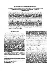
Fig. 6. The 1-D Gray-Scott equation (15) is solved using different time steps ∆t with the same parameters values of figure (2). The final solution obtained at t = 200 is compared, for each method (RK4, ETDRK4 and ETDRK4-B), with a gold-standard run (computed with ETDRK4B and ∆t = 10−5 ); the maximum absolute errors are displayed as a function of the time step.
µ4 = eL∆t Un + ∆t [φ0 (L∆t) − 2φ1 (L∆t)] Nu (Un , Vn , tn ) + 2∆tφ1 (L∆t)Nu (µ3 , ν3 , tn + ∆t). The functions φi are defined as ez − 1 ez − 1 − z ez − 1 − z − z 2 /2 , φ1 (z) = φ (z) = 2 z z2 z3 and these are precisely the terms that emerge naturally in the Lie group methods [Munthe-Kaas 1999]. The original Cox & Matthews scheme involves a split-step and has marginally worse error and stability properties. There are also slight problems associated with capturing the behaviour of φi (z) uniformly as z → 0 and [Kassam and Trefethen 2003] suggest a remedy; one uses an integral in the complex plane [Higham 1996], and we also use this approach in our algorithms. For brevity we have presented the scheme for U alone, the V equations follow in a similar fashion. We label this as a fourth order Exponential Time Differencing Runge-Kutta (ETDRK4-B) scheme to distinguish it from a standard Runge-Kutta scheme and to be consistent with the notation of [Cox and Matthews 2002; Kassam and Trefethen 2003; Krogstad 2005]. It is also worth noting that various other exponential Runge-Kutta schemes have been developed by other authors, see [Vanden Berghe et al. 2000] and the references therein to overcome this difficulty arising in other contexts. A reasonably large numerical overhead is involved in setting up the fourth-order scheme using the device suggested by [Kassam and Trefethen 2003]; if one utilizes an adaptive scheme in time then this overhead must be regularly recomputed and this then becomes expensive, hence we do not adapt the ETDRK4 schemes in time. A numerical 1-D comparison of the ETDRK4 scheme of ([Cox and Matthews 2002]), the improved ETDRK4-B ([Krogstad 2005]), and the more standard RK4 scheme is shown in figure (6). It is noticeable that ETDRK4-B proved to give the smaller error; both it and the ETDRK4 scheme provide an order of magnitude improvement over the RK4 scheme for larger timesteps, rewarding the extra programming effort. The errors all scale with the expected ∆t4 scaling. φ0 (z) =
Technical Report. Note del Polo, No. 99, 2006.
14
·
R. V. Craster & R. Sassi RK4 ETDRK4−B ETDRK4 CK45
−3
Absolute Error
10
−4
10
−5
10
0
10
1
2
10
10
3
10
Time
Fig. 7. Absolute errors of the computational methods with respect to a gold-standard run obtained with ETDRK4-B using ∆t = 0.01. The 2-D equation being solved is (19), which leads to labyrinthine patterns. Most schemes (RK4, ETDRK4, ETDRK4-B) use a fixed time step of ∆t = 0.1, CK45 adapts its time step to contain local absolute error below 10−4 , leading to an average ∆t ≈ 0.62. The smaller computational time (about 11.6 against 22.7 minutes) is paid out with a larger error. Note that Matlab is not very efficient when it comes to loops; with Fortran the difference in execution times is wider (2.5 versus 8.7 minutes).
Although from a practical point of view all of these schemes are explicit and so are much better (faster, accurate) than the implicit, or semi-implicit schemes often used for these equations. This must be the main message to be taken from this article. In figure (7) a 2-D comparison is performed. As well as the previous schemes, we also employed the Cash-Karp version of the RK4 scheme that adapts the timestep (the overhead is small, easily allowing this). It is, again, clear that the ETDRK4 and ETDRK4-B schemes are more accurate and over longer times ETDRK4-B is the preferred scheme. The adaptive method is very fast, and the accuracy can be improved by lessening the error tolerances, and thus it is recommended for longer, more time-consuming, computations. 4. CONCLUDING REMARKS We have developed and packaged a suite of algorithms for solving reaction diffusion equations. To make the algorithms immediately relevant and directly usable for those in the reaction diffusion equations community we have illustrated the algorithms upon recent and varied examples from the literature. Probably the most striking feature to emerge is how splendidly the method copes with sharp variations in the solutions, and also how fast and accurate the method is even with large timesteps. But, before further congratulating ourselves upon the efficiency of spectral methods we must discuss several disadvantages: The scheme we present is utterly reliant upon the reaction-diffusion equations being semi-linear, that is, the diffusion terms are simply uxx + Cuyy and similarly for v; for some constant C (we have simply had isotropic diffusion in this article). We have not discussed possible problems with aliasing, earlier versions of our code utilized Orzag’s 2/3 rule to filter this out. However, this actually made no Technical Report. Note del Polo, No. 99, 2006.
Reaction-diffusion equations
·
15
discernable difference to the solutions and we later just discarded this. It is evident that the method has terms exp(−Ω2 ∆t) so higher order modes are, in any case, exponentially decaying; aliasing transfers some lower order modes to higher ones, so for diffusion-like problems the aliasing is automatically damped. Nonetheless aliasing is an issue that should be borne in mind in any spectral scheme. Fourier spectral methods require periodicity, and we are not in the position, at least here, to set Neumann or Dirichlet boundary conditions on the edge of the domain. That requires an extension to Chebyshev, or some other basis functions. Thus we have to take the domain size large enough that the waves, pulses, structures of interest do not interact with the edges of the domain. In fact, one can set up and indeed solve Dirichlet/ Neumann boundary condition problems using integrating factor methods, see for instance [Kassam and Trefethen 2003], but there is then an essential difference. One must take the exponential of a full matrix, the periodic case treated here is special as those matrices are then diagonal and this simplification underlies all that we have done here, and computing the exponential of a matrix is numerically expensive particularly if it must be re-computed. This is an area that deserves further thought and work as the prospective pay-off in generating explicit timestepping codes for stiff PDEs in high spatial dimensions is considerable. In some cases spectral accuracy means that we can use so few modes that the graphical solutions look unnaturally poor. This is despite the isolated values at the grid points being spectrally accurate, we can then utilize interpolation onto a finer grid using periodic cardinal functions, an algorithm for 1D is supplied in [Weideman and Reddy 2001]. We present an alternative, and generalization to 2D, in Appendix B based upon padding a Fourier transform with zeros. Note that we are not claiming that the codes herein are the absolute best algorithms available for reaction-diffusion equations, nor do we attempt to imply that other scientists using alternative algorithms have been misguided. In particular, in 1D, the adaptive scheme of [Blom and Zegeling 1994] has proved itself to be a useful and accurate algorithm that we have enjoyed working with. One alternative scheme that certainly suggests itself is an Alternating Direction Implicit scheme where spatial discretization is again done through spectral methods, for completeness we provide a Matlab code that does this and we discuss this further in an appendix. In essence, we find that the low-order time solver usually used means that the scheme performs much less well than the integrating factor method of the main text. Our aim has been, and is, to provide good, clear, working, versatile spectral schemes, that avoid stiffness issues, in a form whereby they can be utilized and built upon by other scientists. Thus, we hope, allowing them to concentrate upon the physics, biology, chemistry or other scientific issue rather than upon numerical concerns; the codes are summarized in table I, and are documented both internally and via an electronic README file.
Technical Report. Note del Polo, No. 99, 2006.
16
·
R. V. Craster & R. Sassi
Table I. A schematic tree of the provided algorithms. Names and corresponding equations are matched in the lower table. Fortran |-- OneD | |-- CK45 | | |-- auto_CK45.f | | |-- epidemic_CK45.f | | |-- fisher_CK45.f | | ‘-- gray1D_CK45.f | |-- ETDRK4_B | | |-- auto_ETDRK4_B.f | | |-- epidemic_ETDRK4_B.f | | |-- fisher_ETDRK4_B.f | | ‘-- gray1D_ETDRK4_B.f | ‘-- RK4 | |-- auto_RK4.f | |-- epidemic_RK4.f | |-- fisher_RK4.f | ‘-- gray1D_RK4.f ‘-- TwoD |-- CK45 | |-- gray2D_CK45.f | ‘-- labyrinthe2D_CK45.f |-- ETDRK4_B | |-- gray2D_ETDRK4_B.f | ‘-- labyrinthe2D_ETDRK4_B.f ‘-- RK4 |-- gray2D_RK4.f ‘-- labyrinthe2D_RK4.f Useful |-- adifisher.m |-- fourierupsample.m |-- fourierupsample2D.m |-- plot_fisher2D.m |-- plot_gray2D.m ‘-- plot_labyrinthe2D.m
1-D
2-D
Matlab |-- OneD | |-- CK45 | | |-- auto_CK45.m | | |-- epidemic_CK45.m | | |-- fisher1D_CK45.m | | ‘-- gray1D_CK45.m | |-- ETDRK4 | | ‘-- gray1D_ETDRK4.m | |-- ETDRK4_B | | |-- auto_ETDRK4_B.m | | |-- epidemic_ETDRK4_B.m | | |-- fisher1D_ETDRK4_B.m | | ‘-- gray1D_ETDRK4_B.m | ‘-- RK4 | |-- auto_RK4.m | |-- epidemic_RK4.m | |-- fisher1D_RK4.m | ‘-- gray1D_RK4.m ‘-- TwoD |-- CK45 | |-- fisher2D_CK45.m | |-- gray2D_CK45.m | ‘-- labyrinthe2D_CK45.m |-- ETDRK4 | ‘-- labyrinthe2D_ETDRK4.m |-- ETDRK4_B | |-- fisher2D_ETDRK4_B.m | |-- gray2D_ETDRK4_B.m | ‘-- labyrinthe2D_ETDRK4_B.m ‘-- RK4 |-- fisher2D_RK4.m |-- gray2D_RK4.m ‘-- labyrinthe2D_RK4.m
File Name auto epidemic fisher1D gray1D fisher2D gray2D labyrinthe2D
Technical Report. Note del Polo, No. 99, 2006.
ref. Equation (16) (2) (13) (15) Appendix C (18) (19)
Reaction-diffusion equations
·
17
APPENDIX A. THE ONE DIMENSIONAL MATLAB CODE function gray1D_RK4(N,Nfinal,dt,ckeep,L,epsilon,a,b) if nargin