Port Said Engineering Research Journal Port Said University
Faculty of Engineering
Volume 16 No. 1 pp: 176 :182
Current-Mode Readout of Dynamic Random-Access Memories Sherif M. Sharroush1, , Ahmed A. Dessouki2, Yasser S. Abdalla3, and El-Sayed A. El-Badawy4
Abstract During the reading of one-transistor one-capacitor dynamic random-access memory (1T-1C DRAM) cells, the need arises to amplify a small voltage difference (in the order of 30 to 100 mV) by a suitable sense amplifier. The net result is that the higher voltage will rise to VDD while the lower one will decrease to 0 V. Simulation results for the 0.13 µm CMOS technology with VDD=1.2 V reveals that about 40% of the read access time is associated with the sense amplifier operation in addition to the area required by each sense amplifier for each column in the memory array. In this paper, a novel current-mode readout technique for use with DRAM cells is presented. This method depends on converting the bitline voltage to a current to be compared with a reference current. The positive-feedback effect of the current comparator then comes into action with the result that one of its outputs will be the required output data taken at a much smaller parasitic capacitance compared with the bitline parasitic capacitance. Simulation results for the 0.13 µm CMOS technology show that about 10% of the read access time can be saved. The, the power-delay products in case of reading "1" (the worst case from the point of view of PDP) are 388.5 fJ and 188 fJ for the conventional and proposed schemes, respectively. Key Words: dynamic random-access memory, read cycle time, sense amplifier, current comparator. I. INTRODUCTION Dynamic random-access memories (DRAMs) are widely used in computer systems as the primary storage due to its relatively fast access especially if compared with hard disks and due to its relatively high density compared to static RAMs. However, DRAMs suffer from bad retention due to the inevitable leakage currents that discharge the storage capacitor. In this paper, the conventional reading scheme of 1T-1C DRAM cells is discussed and a proposed current-mode reading scheme is presented. The proposed scheme depends on converting the bitline voltage to a current to be compared with a reference current. The positive-feedback effect of the current comparator then comes into action with the result that one of its outputs will be the required output data taken at a much smaller parasitic capacitance compared with the bitline parasitic capacitance. The dynamicpower consumption is consequently reduced.
II. CONVENTIONAL SCHEME Although a variety of DRAM storage cells have been proposed over the years [1-5], a particular cell, shown in Fig. 1, has become the industry standard. The cell consists of a single access transistor, M, and a storage capacitor, Cs, and thus is known as the 1T-1C DRAM cell. The cell stores one bit of information in the form of charge on Cs.
bitline wordline
M C BL
The remainder of this paper is organized as follows: Section II presents the conventional reading scheme for 1T-1C DRAM cells while the proposed reading scheme is presented in Section III. The proposed reading scheme will be investigated quantitatively in Section IV. The impact of CMOS technology scaling on the proposed scheme is discussed in Section V. The proposed scheme will be simulated adopting the 0.13 µm CMOS technology with the simulation results presented in Section VI. Finally, the paper will be concluded in Section VII. ___________________________________________
Cs
Fig. 1 The one-transistor one-capacitor dynamic RAM cell [6].
The write operation proceeds as follows: The wordline, WL, is first activated to a boosted voltage of VDD + Vthn. Depending on whether the data to be written is logic "1" or logic "0", the bitline, BL, will be activated to VDD or 0 V, thus causing the storage capacitor, Cs, to be charged to VDD or discharge it to 0 V, respectively.
1
Dept of Elect Eng, Fac. of Eng., Port Said, Suez Canal Univ., Egypt. EM:
[email protected] 2 Dept of Elect Eng, Fac. of Eng., Port Said, Suez Canal Univ., Egypt. EM:
[email protected] 3 Dept of Electricity, Fac. of Industrial Edu., Suez, Suez Canal Univ., Egypt. EM:
[email protected] 4 Alex Higher Inst. Of Eng. and Tech & Fac. of Eng., Alex. Univ., Alexandria, Egypt. EM:
[email protected]
Now, the conventional reading operation of the DRAM memory cells will be discussed. Refer to Fig. 2 for illustration [7]. First, the two bitlines, BL and BL , connected to the sense amplifier terminals will be pre-
671
charged to VDD/2 and equalized to that voltage in order to block the effect of any noise on these lines where the complementary bitline is connected to a dummy cell. This is due to the fact that the differential voltage generated between the two bitlines, BL and BL , is small (typically 30 mV) for modern CMOS technologies. The wordline, WL, is then activated to a boosted voltage, VDD + Vthn. This turns on Qc and charge sharing occurs between the cell capacitor, Cs, and the bitline parasitic capacitance, CBL. If the cell to be read stores "1", then the cell capacitor, Cs, is initially charged to VDD and thus the bitline voltage, VBL, rises from VDD/2 to VDD/2+∆V. The small differential voltage, ∆V, between the two bitlines, BL and BL , will be amplified by virtue of the sense amplifier until the BL rises to VDD and BL decreases to 0 V. The final bitline voltage, VDD, is used to writeback the stored data to the memory cell as the access transistor, Qc, is still activated. BL
V BL1
C sV DD C BL C s C BL
V DD 2 .
(2)
On the other hand, in case of "0" storage the capacitor, Cs, charges from 0 to VBL0 while CBL discharges from VDD/2 to VBL0. So,
V C s VBL 0 0 C BL DD VBL 0 2
VDD 2 Cs C BL
(3)
C BL
VBL 0
.
(4)
The main disadvantage of this reading scheme is the following: The output data will be available at the bitline after a relatively long time (21 ns according to our simulation for the 0.13 µm CMOS technology). This is due to the need to rise or decrease the voltage of the bitline parasitic capacitance, CBL, which is relatively large (typically 256 fF for the 0.13 µm CMOS technology) due to its connection to the access transistors in all the memory cells in the columns (typically there are 128 cells in each column).
BL
WL Memory cell QC CS
CBL
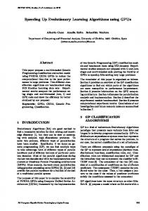
III. PROPOSED SCHEME In this section, a current-mode readout scheme for reading the 1T-1C DRAM cell is presented. Refer to Fig. 3 (a) for the peripheral circuitry needed to precharge the bitline and read the stored data in each column and to Fig. 3 (b) for the timing diagram showing the synchronization of the employed signals. According to this technique, there will be no sense amplifier, however, there will be a current comparator. Basically, during the reading access, there will be a voltage signal generated on the bitline. This voltage signal will be converted to a current by M1 that acts as a voltage-to-current converter. At the beginning of the reading access, the precharge signal, PRE, will be at logic "0", thus activating the PMOS transistor, Mp1. This will cause the bitline parasitic capacitance, CBL, to precharge to Vthn. Note that the threshold voltage of the precharge transistor, Mp1, must be adjusted in order to allow conduction of the this transistor.
C BL
sense amplifier
precharge
Fig. 2 The conventional reading scheme of the 1T-1C DRAM cell [7].
Had we assumed that the cell stores "0", the cell capacitor, Cs, is initially discharged to 0 V and thus upon charge sharing between CBL and Cs, the bitline voltage, VBL, will decrease from VDD/2 to VDD/2 - ∆V. By virtue of the positive feedback effect of the sense amplifier, the bitline voltage finally decreases to 0 V which will also be used to writeback the stored data on the memory cell. The steady-state voltages of the bitline can be found from the principle of charge conservation, that is; the charge lost by one capacitance equals that acquired by the other. In case of "1" storage, the cell capacitor, Cs, discharges from VDD to VBL1 while CBL charges from VDD/2 to VBL1. So, the amount of the charge lost by Cs is equal to that acquired by CBL, i.e.
V C s VDD VBL1 C BL VBL1 DD 2
(1)
677
M2 operate as voltage-to-current converters that convert their two gate voltages, VBL and VB, (the biasing voltage of M2) into two currents, i1 and i2, respectively. The reference current, i2, acts as a reference for comparison with i1 that depends on the stored data. If the cell stores "1", then VB is adjusted such that i1 will be larger than i2 for "1" storage, thus pulling the voltage at node out down and by the effect of the positive feedback caused by M3 and M4 the voltage at node out will be at VDD which is the required output data. On the other hand, if the cell stores "0", then due to the charge sharing between Cs and CBL, VBL will decrease from Vthn to
VBL 0
C BLVthn C BL C s
(6)
which is certainly lower than Vthn. So, i1 will be zero except for the subthreshold-leakage current of M1. If VB is chosen to be larger than Vthn, then i1 will be smaller than i2 for "0" storage. So, the out node voltage will rise to VDD and by the effect of the positive feedback of M3 and M4, the out node voltage will be decreased to 0 V as it must do.
(a)
The reading operation according to this method is obviously destructive. So, the stored data must be written back. This is in fact the role of the three transistors, M5, M6, and M7. In order to write back the stored data, the two signals, VA and WB, are activated. Obviously, if the read data is logic "1", then the voltage at out will be at 0 V. This causes the voltage at the gate of M5 to be at 0 V, thus deactivating it. The read data will then be written back through M7. Oppositely, if the read data is logic "0", then the voltage at out will be at VDD. This activates the transistor, M5, thus pulling down the voltage at node, out, to 0 V. It must be noted that the connection of the transistor, M5, not only contributes in writing back the read data, but also speeds-up the reading process and enhances the noise margin in case of "0" storage. In fact, if M5 is eliminated, the data will be erroneously read in case of "0" storage. This point will be returned to in Section VI.
(b) Fig. 3 (a) The circuit schematic of the peripheral circuitry of the current-mode readout scheme, (b) The timing diagram showing the signals, PRE, WL, VA, VB, CCA, and WB.
The wordline, WL, will be activated to a boosted voltage, VDD + Vthn, thus activating the access transistor, Qc, while the signal, VA, is still at logic "0", thus deactivating M6. If the cell stores "1", then its cell capacitor, Cs, will be initially charged to VDD. So, Cs will lose some of its charge to CBL through the access transistor, Qc, as in the previous method. The final voltage on CBL in case of "1" storage will thus be
VBL1
C sVDD C BLVthn , C BL Cs
Specifically, in case of "0" storage, the voltage at node out will not be at precisely 0 V. Instead, it will be at a voltage that is higher than 0 V which is considered a poor "0". This is due to the continuous conduction of M2 by the biasing voltage source, VB, with the result that M3 and M2 form a voltage divider. This causes not only the noise margin to be poor in case of "0" storage, but also there will be a short circuit current through the Mp-M3M2-MN branch, thus increasing the power consumption associated with reading "0". Pulling down the voltage at out by increasing the voltage, VB, has a deleterious effect in case of reading "1" as the current, i2, will be larger than i1 in case of reading "1" or smaller than it by a slight amount. However, with the connection of M5, the VDD voltage at the out node activates the transistor, M5, thus pulling down the voltage at node out to perfect 0 V.
(5)
which is certainly larger than Vthn. Now, refer to the current comparator used at each column in the memory array instead of the sense amplifier which will be activated by the CCA (current-comparator activation) signal. It consists of four transistors, M1, M2, M3, and M4. M1 and
671
VBL 0
Speeding-up the reading process in case of "0" storage id due to the following: When the voltage at out increases, the voltage at out decreases further by the effect of M. This causes the PMOS transistor, M4, to charge the parasitic capacitance, C2, at node out . This positivefeedback effect results in faster operation.
VDD
VCS1(t)
VBL1
VBL1(t)
Vthn
VBL0
VBL0(t) VCS0(t)
0V
It should be noted that the read data cannot be written back by the use of a single NMOS transistor connected between the node out and the bitline. This is due to that in the case of stored "1", the bitline parasitic capacitance, CBL, will discharge to 0 V through the series connection of the fictitious write-back transistor and M2, thus resulting in an erroneous output. However, in case of stored "0", both CBL and C1 discharge through the same path resulting in correct reading and write back. As a final remark on this scheme, any other current comparator can be used. Also, there will be no need to use an equalization circuitry or dummy cells as in the conventional scheme.
VBL1
VBL0
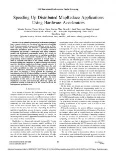
wordline activated Fig. 4 A qualitative plot showing the change of the voltages across the bitline parasitic capacitance, VBL, and the cell storage capacitor, VCs, in case of stored "1" and stored "0" upon charge sharing between CBL and Cs. Note the larger change in case of stored "1" (The graph is not to scale).
Consequently, it is expected that VB must be larger than Vthn in order to compensate for this difference. This must be compared to the conventional readout method in which the other input terminal of the sense amplifier is connected to a voltage of VDD/2 through say a dummy cell [1].
IV. QUANTITATIVE ANALYSIS In this section, the proposed scheme will be analyzed quantitatively seeking to discuss the range within which we can choose the biasing voltage, VB, along with the optimum value for this voltage, VBopt.
The key point behind the determination of the optimum value for VB, VBopt, is the following statement: The sum of the differences between the reference current and the two currents generated from M1 in case of stored "1" and "0" is maximized and these two differences are equalized. Toward this target, the reference current, i2, will be put equal to the arithmetic average of the two currents passing through M1 in case of "1" storage, i11, and "0" storage, i10, respectively, that is
The Optimum Value of the Biasing Voltage, VB From the qualitative discussion of the proposed readout scheme in Section III, it is apparent that the biasing voltage, VB, must be chosen such that the current flowing through M2, i2, is larger than that flowing through M1, i1, in case of "0" storage and smaller than i1 in case of "1" storage. A quick look at the circuit of the proposed scheme may reveal that a suitable value for VB is Vthn as the voltage to which the bitline, BL, is initially precharged is Vthn. However, the simulation results contradict with this guess and prove that VB = Vthn is not a right choice as the stored "0" will be misread.
i2
i11 i10 2
(9)
Since in case of stored "0", VBL0 will be smaller than Vthn, i10 will ideally be zero. However, in case of stored "1", VBL1 will be slightly larger than Vthn, so M1 will certainly operate in the saturation region since its VDS will be larger than its overdrive voltage, VGS - Vthn. So,
The reason behind this is that the voltage difference between the bitline parasitic capacitance, CBL, and the storage capacitor, Cs, in case of stored "1" is larger than that in case of stored "0". In the former, it is VDD - Vthn while in the latter it is Vthn. So, the differential voltage signal appearing on the bitline in case of stored "1" will certainly be larger than that in case of stored "0". This can be quantified by the following equations:
CsVDD CBLVthn Cs CBL
(8)
Eqs. (7) and (8) for the final values of the bitline voltages in case of stored "1" and stored "0", respectively. Refer to Fig. 4 for illustration.
A word of caution here concerning the instant of time at which the WB signal is activated is in order. If this signal is activated earlier than necessary, the voltage at node out will not rise to VDD in case of reading "1"; instead it will discharge through M7 resulting in wrong output data.
VBL1
C BLVthn C BL C s .
i11
1 ' W 2 k n VBL1 Vthn 2 L 1
(10)
where the channel-length modulation effect is neglected. The final voltage on the bitline in case of stored "1" can be found using the principle of charge sharing as discussed in Section II to be
(7)
671
C V CBLVthn VBL1 s DD CBL Cs
.
total access time is expected to increase. However, it remains below the precharging time interval of the conventional scheme in which CBL is initially precharged to VDD/2 as soon as Vthn remains below VDD/2. The precharging time interval, however, of the conventional scheme remains the same as VDD and the precharge level decreases by the same ratio from one technology generation to the next. If the VDD/Vthn ratio reaches 2, then VDD/2 will be equal to Vthn and the precharging time delays of the conventional and proposed readout schemes will be the same. Also, the need arises in this case to adjust the threshold voltage of the precharging PMOS transistor in the conventional scheme.
(11)
Substitution of this value for VBL1 into Eq. (10) results in
1 W C V C BLVthn i11 k n' s DD Vthn 2 L 1 C BL C s i11
2
1 ' W C sVDD C BLVthn C BLVthn C sVthn kn 2 L 1 C BL C s
1 ' W C s VDD Vthn kn 2 L 1 C BL C s So, the reference current will be chosen to be
2
2
i11
i2
i11 i10 i11 2 2
(12)
(13)
1 W 1 W C V V 2 k n' VBopt Vthn k n' s DD thn 2 L 2 4 L 1 C BL C s
To investigate the impact of the reduction of the VDD/Vthn ratio on the ratio between the two sense margins in case of "0" and "1" readings, SM0 and SM1, respectively, refer to Eqs. 9 and 6 for VBL1 and VBL0. They will be repeated here for convenience.
2
VBL1
VBL 0
After simple mathematical manipulations, we can obtain
V Bopt Vthn
CsVDD CBLVthn Cs CBL
(15)
C BLVthn . C BL C s
(16)
So, the sense margins in case of "1" and "0" readings will be
1 W / L 1 C s V DD Vthn . (14) 2 W / L 2 C BL C s
SM1 VBL1 VBL1 Vthn
For the 0.13 µm CMOS technology which is adopted in the simulation in this thesis, VDD = 1.2 V and Vthn = 0.4 V. Considering Cs and CBL to be equal to 10 fF and 250 fF, respectively and assuming that (W/L)1 = (W/L)2, we obtain upon substitution into Eq. (14),
Cs VDD Vthn Cs CBL
(17)
and
SM 0 VBL 0 Vthn VBL 0
CsVthn Cs C BL
,
(18)
respectively. The ratio between SM1 and SM0 is thus
VBopt = 0.4217 V. If the same parameters that are used in computing VBopt were used in computing VBL0 and VBL1, we will get VBL0 = 0.384 V and VBL1 = 0.43 V. It is obvious that VBopt is not equal to the arithmetic average of VBL0 and VBL1. This is an expected result since the reference current, i2, is equal to the arithmetic average of the two currents generated through M1 in case of stored "1" and stored "0" and these two currents are not linearly related to the corresponding gate voltages. Instead, there is a square-law dependence.
SM1 Cs VDD Vthn VDD 1. SM 0 CsVthn Vthn
(19)
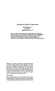
So, with technology scaling, the ratio between SM1 and SM0 decreases until we arrive at the case VDD = 2Vthn at which the two sense margins are equal. In fact, this case corresponds to precharging the bitline to VDD/2 as in the conventional scheme. Refer to Fig. 5 for illustrating the impact of technology scaling on SM1 and SM0.
Finally, it should be noted that the speed of this scheme is more sensitive to the change in Cs than the conventional scheme as increasing Cs causes the current, i1, to increase significantly due to the square-law dependence.
VDD
VDD VBL1
Vthn
VDD 2
VBL0
VBL0
0V
0V
V. IMPACT OF TECHNOLOGY SCALING 1. Reduction of the VDD/Vthn Ratio Due to the need to reduce the dynamic power consumption and enhance the reliability of short-channel devices, the power-supply voltage, VDD, reduces at a rate that is faster than that of Vthn from one technology generation to the next [8]. So, the ratio VDD/Vthn decreases. Since CBL is precharged to Vthn instead of VDD/2, the percentage of the precharging time interval relative to the
VBL1
wordline activated
wordline activated
Fig. 5 The effect of the reduction of the VDD/Vthn ratio on the sense margins of "1" and "0" readings, SM1 and SM0, in the proposed method. Note the equalization of the sense margins, SM1 and SM0, with technology scaling.
2. Velocity Saturation and Mobility Degradation
611
Due to the velocity saturation, the drain current will no longer be related to the gate-to-source voltage through a square law. However, it will be related to VGS through the following relationship [9]:
i D K VGS Vthn
VI. SIMULATION RESULTS The proposed reading scheme is simulated for the 0.13 µm CMOS technology with VDD =1.2 V using Multisim 11. The simulation results for this scheme are shown in Figs. 6 and 7 for stored "1" and stored "0", respectively. Shown in these figures are the voltages across the cell capacitor, VCs, across the bitline parasitic
(20)
where K is a parameter that depends on the CMOS technology and the device dimensions and is equal to 2 in long-channel MOSFETs with channel lengths longer than typically 1µm. If we proceed with the analysis of Section IV concerning the determination of VBopt, the following two currents will be obtained in response to VBL0 and VBL1;
i11 K VBL1 Vthn
capacitance, VBL, and the voltages at the out and out nodes with the biasing voltage source, VB, put equal to 0.42 V. Also, shown in Fig. 8 are the simulation results for stored "0" when the transistor, M5, is not connected. Note that the voltage at node out will not be perfectly 0 V. The access time is approximately 18 ns compared to 20 ns for the conventional scheme. The, the power-delay products in case of reading "1" (the worst case from the point of view of PDP) are 388.5 fJ and 188 fJ for the conventional and proposed schemes, respectively.
(21)
and
i10 0 .
(22)
If the two transistors, M1 and M2, have different sizes, then the drain current can be related to the device dimensions through
W i11 K1 VBL1 Vthn L 1
(23)
where K1 is a parameter that depends on the CMOS technology. So,
W C V C BLVthn i11 K1 s DD Vthn L 1 C BL Cs
W C V C BLVthn C BLVthn C sVthn i11 K1 s DD C BL C s L 1
W C V Vthn i11 K1 s DD L 1 C BL C s
Fig. 6 The simulation results showing the voltages across the cell capacitor, the bitline parasitic capacitance, at the out and out nodes for stored "1".
.
(24)
So, the reference current will be
i2
W K 1 VBopt Vthn L 2
VBopt Vthn
i11 i10 i11 2 2
1 W / L 1 2 W / L 2
1 W C s VDD Vthn K1 2 L 1 C BL C s
C s VDD Vthn C BL C s
Fig. 7 The simulation results showing the voltages across the cell capacitor, the bitline parasitic capacitance, at the out and out nodes for stored "0".
(25)
α is typically 1.3 in short-channel devices. Substituting this value for α in Eq. (25) and assuming the same values for Cs and CBL as that substituted in Eq. (14) along with the assumption of (W/L)1 = (W/L)2 results in VBopt = 0.424 V, which is far from the arithmetic average of VBL1 and VBL0 than the value obtained in the analysis of Section IV assuming long-channel devices.
Fig. 8 The simulation results showing the voltage at the node, out, for stored "0" when the transistor, M5, is eliminated which is an erroneous output data.
616
VII. CONCLUSIONS There is no doubt that, dynamic RAMs play a significant role in all computing and control devices. The conventional reading process of one-transistor one-capacitor dynamic RAMs requires the use of a sense amplifier that compares between the bitline voltage and the dummy bitline voltage, then amplifying the voltage difference between them. However, this takes a relatively long time. In this paper, a novel reading technique was proposed. This technique depends on converting the voltage change generated on the bitline due to charge sharing between Cs and CBL to a current change and using a current comparator instead of the sense amplifier in order to speed-up the operation. The access time is approximately 18 ns compared to 20 ns for the conventional scheme. The, the power-delay products in case of reading "1" (the worst case from the point of view of PDP) are 388.5 fJ and 188 fJ for the conventional and proposed schemes, respectively. REFERENCES [1] J. Wood and R. G. Wood, "The Use of Insulated-Gate Field-Effect Transistors in Digital Storage Systems," ISSCC Digest of Technical Papers, pp. 82-83, England, February 1965. [2] Digest of Technical Papers of the IEEE International SolidState Circuits Conference (ISSCC), February of each year. [3] W. M. Regitz and J. A. Karp, "A Three-Transistor Cell, 1024-bit, 500 ns MOS RAM," ISSCC Digest of Technical Papers, pp. 36-39, USA, February 1970. [4] Digest of the IEEE International Electron Devices Meeting (IEDM), December of each year. [5] R. H. Dennard, "Filed-Effect Transistor Memort," U. S. Patent 3387286, Jun. 4, 1968. [6] A. S. Sedra and K. C. Smith, Microelectronic Circuits, Fourth Edition, New York: Oxford, 1998. [7] R. C. Jaeger, T. N. Blalock, Microelectronic Circuit Design, Second Edition, McGraw-Hill, 2004. [8] V. Kursen et al., Multi-Voltage CMOS Circuit Design, John Wiley & Sons Ltd., 2006. [9] D. A. Hodges, H. G. Jackson, and R. A. Saleh, Analysis and Design of Digital Integrated Circuits: in Deep Submicron Technology, McGraw-Hill, Third Edition, 2003.
611