Spread-Spectrum Techniques for Distributed Space-Time Communication in Sensor Networks R. Mudumbai
G. Barriac
U. Madhow
Department of Electrical and Computer Engineering University of California Santa Barbara, CA 93106 Email:
[email protected]
Department of Electrical and Computer Engineering University of California Santa Barbara, CA 93106 Email:
[email protected]
Department of Electrical and Computer Engineering University of California Santa Barbara, CA 93106 Email:
[email protected]
Abstract— Communication is widely acknowledged as a fundamental bottleneck in sensor networks with large numbers of lowcost, low-power nodes. We consider cooperative transmission of a common message signal from a cluster of sensor nodes to a remote receiver, under realistic transmission models accounting for timing and frequency synchronization offsets across the nodes. The purpose is to obtain range extension by combining the powers of the nodes in a cluster, and to obtain robustness against channel impairments by exploiting the diversity naturally arising from the spatial distribution of the sensor nodes. For a simple scheme in which all nodes asynchronously transmit the same signal, we analyze the available diversity gains using an informationtheoretic analysis of outage capacity for wideband systems. We show that standard modulation formats can be adapted to realize diversity gains in the presence of synchronization errors. We propose simple receiver architectures that realize diversity gains and have desirable scaling properties as the number of sensors increases.
I. I NTRODUCTION While the conventional approach to wireless networking is to view nodes as autonomous entities which coordinate at the medium access layer and above, there are large potential gains from coordinating node transmissions at the physical layer. This is of particular interest for large scale sensor networks, in which nodes operate under severe power and energy constraints. We consider distributed space-time communications, in which a cluster of sensor nodes coordinate their transmission of a common message to emulate a centralized antenna array. Our objective is to determine, under realistic models of synchronization across the nodes in the cluster, whether the powers of the sensor nodes can add up to provide significant range extension, and whether the natural spatial distribution of sensor nodes leads to spatial diversity. Previous work on cooperative transmission has primarily focused on distributed coding to realize diversity gain. Typically, this requires the sensor transmissions to be separated in frequency or time or code-space, and the receiver is required to demodulate and combine the transmissions separately. In practice this means that the useful communication range is restricted by the power of each sensor’s transmission. Our This work was supported by the Office of Naval Research under grant N00014-03-1-0090, and by the National Science Foundation under grants ANI 0220118 and EIA 0080134
work is motivated by the possibility of the sensors transmitting together to achieve an increased SNR at receiver, or equivalently an increased communication range. Essentially, the sensor nodes’ combined transmission can be modeled as a virtual SISO channel. However, synchronization errors between sensors limit the performance of such a system, by introducing delay and Doppler spreads in the virtual channel. The virtual channel induced by distributed transmission is temporally selective because of “Doppler effects” arising from carrier synchronization errors, and is frequency selective because of the delay spread resulting from timing errors across the sensor nodes, and the differences in the channel path delays from different sensor nodes to the receiver. Such selectivity occurs because of synchronization errors, even if each sensor node sees a line-of-sight link to the receiver. Rather than trying to mitigate these impairments, we propose using wideband signaling to exploit the delay spread to realize diversity gains. Effectively, we would convert spatial diversity into frequency diversity, by using the sensor nodes as active scatterers to create a virtual channel. In this paper, we attempt to quantify the available diversity gains, for a simple repetition coded distributed communication system using wideband transmission, and identify performance limits for practical physical layer schemes under loose synchronization assumptions. Related Work: There has been considerable recent interest in cooperative transmission schemes for diversity [1] and beamforming [2], [3] gains. In [4], the authors consider “amplify-and-forward” and “decode-and-forward” types of relays and show that maximum diversity gains (equal to the number of degrees of freedom in the channel) are achievable with those protocols. In [5], the authors extend these results to a more general cooperative space-time coding system and derive expressions for the achievable diversity gains. For conventional MIMO systems based on centralized antenna arrays at the transmitter and/or receiver, diversity and multiplexing tradeoffs have been explored in [6]. We focus on distributed space-time coding for increasing power efficiency in sensor networks, so that our concern is with obtaining diversity gain rather than multiplexing gain. We therefore restrict attention to a single antenna receiver. A virtual SISO channel similar to our own has also been proposed in [7] in
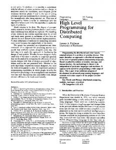
the context of routing in an ad-hoc network, by using network nodes as non-regenerative repeater relays. The previous work on cooperative transmission has generally not addressed synchronization issues. In this paper, we consider synchronization errors from two perspectives: as a degrading effect on performance due to increased intersymbol and co-channel interference, and as an averaging effect resulting in a more predictable and reliable transmission channel. The synchronization requirements considered here are more relaxed than those required for distributed beamforming [2], which requires synchronization of the carrier phases and symbol timings of the collaborating sensors. Outline: Section II describes the use of wideband signaling to realize diversity gains in a virtual SISO channel induced by multiple sensors transmitting simultaneously. We quantify the diversity benefits of using a large bandwidth using an information theoretic analysis of outage rates in Section IIB. Both OFDM and direct sequence signaling are broadly encompassed by this model: a symbol is spread out in time for OFDM, and is spread out in frequency for direct sequence signaling. The performance limits imposed by synchronization errors are explored in Section II-C in the context of OFDM. One way to get around such limits would be to orthogonalize the individual sensors’ transmissions, using e.g. TDMA, FDMA or CDMA, and subsequently combine them for diversity. The problem with this approach is scalability (in terms of complexity of coordination) as the number of sensors increases, and the requirement that the receiver must be able to detect the low power levels from each sensor individually on each orthogonal subchannel. In Section III, we present a simple example of an analog system in which noncoherent envelope detection is employed to combine the powers from simultaneous orthogonal transmissions from individual sensors in a scalable, albeit suboptimal, manner. Section IV concludes the paper. II. D IVERSITY USING WIDEBAND SIGNALING The basic idea of using spread-spectrum signaling for a random channel is illustrated in Figure 1. For a channel with large delay and Doppler spread, making the transmission bandwidth large makes the Doppler spread proportionally small, while making it possible to get good resolution in the time-domain (to resolve multi-path delay spreads). However we do not want to make transmission bandwidth excessively large, where the channel estimation overheads negate the advantages of a large bandwidth [8]. A. System Model We list below the assumptions we make in our model. 1) There is a field of sensors, all of which wish to transmit the same information message to a remote observer (receiver). 2) Each sensor transmits an identically modulated signal over the same frequency band, simultaneously (subject to synchronization errors) to the receiver. As a result, the system can be modeled as a overall virtual channel
multipaths resolved into RAKE "fingers"
Doppler spreads small relative to spread-spectrum signal BW
0
d
time
frequency
0
d
time
frequency
Fig. 1.
3)
4)
5)
6)
fc
fc
Intuition behind spread-spectrum signaling
to the receiver, each sensor acting as a virtual multi-path scatterer, with a certain delay and Doppler shift. Each sensor has a carrier synchronization error (from a nominal carrier frequency) that is bounded. This error leads to a Doppler spread Wd for the virtual channel from the sensor field to the receiver. Each sensor has a random path-length, which leads to a random, uncorrelated phase for each sensor. The path length variation also results in a delay spread, τd for the composite channel. The channel from each sensor has delay spread small compared to timing differences between sensors, and Doppler spreads small compared to carrier synchronization errors between sensors. The timing errors and carrier offsets are independent and identically distributed random processes for each sensor. This allows us to use the classical WSS-US [9] scattering model for the timevarying, multi-path virtual channel. The sensors use broadband (spread-spectrum) signaling, so that the symbol time, Ts is larger than delay spread, τd of the channel and the signal bandwidth, Ws is larger than the Doppler spread, Wd .
For concreteness, we consider the running example of a system with a nominal carrier frequency fc = 2GHz (wavelength λ = 0.15m), the Doppler spectrum uniform with a spread of Wd = 20kHz, and an exponential delay spread with mean τd = 1µsec. These values correspond to a 20 parts-per-million tolerance in carrier frequency offsets, and a timing accuracy readily achievable by using well-known synchronization methods, e.g. [10]. Further, let us assume a transmission bandwidth is Ws = 10M Hz, a sensor transmit power level of PT = −10dBm, and a minimum SNR constraint of SN Rmin = 10dB at receiver. For a receiver noise figure of 6dB and the transmission bandwidth assumed above, we require a signal power at receiver of PR = −88dBm. 2 1 G2 λ Then using a simple path loss model: PR = PT . G (4π)2 r 2 , and antenna gains G1 = 3dB, G2 = 3dB, we have achievable range r ≈ 200m. We seek to improve this transmission range
significantly by using cooperative signaling. B. Channel Model and Outage Analysis Following the treatment in [11], we model the complex PM baseband virtual SISO sensor channel as: h(t, τ ) = m=1 αm (t)δ(τ − τm ), where αm , τm are the amplitude and delay of the m’th sensor’s transmission, and M is the total number of sensors. While the preceding notation assumes a single path from each sensor to the receiver, the model easily accommodates multipath propagation. For a signal bandwidth W , an equivalent Tap Delay Line 1 model with resolution W is given by [11]: h(t, τ ) =
L X l=1
Al vl (t)δ(τ −
l ) W
(1)
where the number of taps is given by L = τd · W , the tap strengths are specified by the power delay profile (Al ∝ q Pτ ( Wl )), with statistical variations due to the superposition of unresolvable paths contributing to a given tap modeled as vl (t) ∼ C(0, 1) (i.e., using a standard Rayleigh fading). Note that if M ≫ 1, the fading process for the virtual channel appears Rayleigh, even if individual sensors have a line-ofsight channel to the receiver. Also, even if the sensors and the receiver are stationary, the fading gains vl (t) exhibit time variations due to carrier phase and frequency offsets across the sensors. Taking Fourier transform of Euation 2 with respect to τ , the time-varying frequency response of the virtual channel is given by H(t, f ) =
L X
Al vl (t)e−j
2πf l W
(2)
l=1
Assuming a uniform power allocation over frequency, we can write an expression for the instantaneous spectral efficiency IW : , and the ergodic rates Cerg (i.e. a Shannon upper bound on IW ) of this fading channel under standard assumptions on the ergodicity and stationarity of the fading process [12]: Z W 1 2 log(1 + SN R |H(t, f )| )df (3) IW = W f =0 Following [11], application of the central limit theorem shows that, if the signal bandwidth is large compared to the coherence bandwidth of the virtual channel, the spectral efficiency IW can be well-modeled as a Gaussian random variable1 . The mean equals the ergodic capacity of a Rayleigh fading channel, while the variance is approximately given by [13] µ ¶2 Z SN R 1 var(IW ) ≈ P 2 (τ ) dτ (4) 1 + SN R W whereR the power delay profile is normalized to integrate to one: P (τ )dτ = 1. This Gaussian approximation provides a
1 The CLT result is established in [11] for the case of Rayleigh distributed channel coefficients, and an exponential PDP, however it is expected to hold for a larger class of fading channels.
simple, yet accurate, approximation for the spectral efficiency attained for a given probability of outage. For example, the spectral efficiency forp1% outage probability is given by R(0.01) = E[IW ] − var(IW )Q−1 (0.01) where Q is the complementary cdf of the standard Gaussian distribution. Multiplying this by the bandwidth W provides an estimate of the outage rate, i.e., the rate attainable with an outage probability of at most 1%. From (5), we see that the variance var(IW ) decreases with 1 W , which shows that the spectral efficiency attained at a given outage probability increases with the signaling bandwidth. For our running example, we can compute Cerg = 3.4b/s/Hz. This system has a coherence bandwidth of approximately Wcoh ≈ 1M Hz. For a transmission bandwidth of Ws = 10M Hz as in our example, the outage rate is 1.5b/s/Hz. This increases to R(1%) = 2.0b/s/Hz for a 20M Hz bandwidth, but decreases to only 0.7b/s/Hz for a 5M Hz bandwidth. This illustrates the frequency diversity available from the system. This diversity gain is in addition to the range extension because of the higher total power at the receiver. Since the sensor transmissions combine incoherently, the received signal strength PR increases linearly with number of sensors M . This √ means that the transmission range increases by a factor M . Increasing M however, does not increase the outage rate beyond a certain point. For M ≫ 1, the virtual channel has rich enough multipath within a delay spread for the virtual channel that is governed by the timing offsets across sensor nodes, so that the diversity depends only on the bandwidth and the delay spread. Of course, the frequency diversity (for a fixed signaling bandwidth) can be increased by artificially increasing the delay spread of the virtual channel by deliberate randomization of the transmission times from different sensor nodes. The preceding outage analysis does not account for time variations in the virtual channel due to frequency offsets across sensor nodes. A coarse quantification of this effect is given in the next section in the context of an OFDM signaling format. C. Time variations in the virtual channel We now consider OFDM, which is a special case of the class of wideband system analyzed in Section II. A traditional OFDM-QAM system [14] uses a guard interval of duration TG ≥ τd with a cyclic prefix for each symbol, to prevent ISI. In order to keep efficiency high, we want to make the symbol time large i.e. Ts ≫ TG . For a fixed total bandwidth W , the number of subcarriers is N = W · Ts , and subcarrier spacing ∆W ≡ T1s . However, ∆W cannot be decreased arbitrarily because the Doppler spread would lead to intercarrier interference i.e. we require ∆W ≫ Wd . Such a system is only feasible if τd · Wd ≪ 1. For the spreads assumed in Section II, τd · Wd ≈ 0.02; therefore OFDM transmission is feasible, e.g. ∆W ∼ 0.5M Hz. However, there is a loss of orthogonality between transmissions on different subcarriers due to the Doppler spread, and hence a SINR degradation. We next present a simple argument for quantifying the SINR degradation that results from the Doppler spread. Since each
W /∆W=0.04 d
400
asymptotic value
SINR
300
zero−ICI case
200
100
0
0
20
40
60
80
100
120
140
160
180
200
140
160
180
200
number of sensors 1200 1000
range (m)
sensor’s transmission is independent, let us consider a single sensor with carrier frequency offset Wd . (The timing error does not cause any degradation as long as it is smaller than the guard interval TG .) We consider the OFDM symbol as a vector in a space spanned by the subcarriers, which form an orthonormal basis, i.e. each subcarrier i = 1..N can be represented by the frequency domain basis function pi (ω) = sinc( ω−i.∆W ). For a large number of subcarriers, ignoring ∆W edge effects, the average signal power and interference power is the same for all subcarriers. Also the ICI contribution from each sensors transmission is just the total received power minus the power associated with the main subcarrier (the useful power). Since the pi (ω) form an orthonormal basis, we can compute the “useful power” contribution by a simple projection: Z ∞ pi (ω)pi (ω − Wd )dω (5) Rp =
800 600 400
singe−sensor range
200 0
0
20
40
60
80
100
120
number of sensors
Fig. 2.
SINR variation and range increase for OFDM
ω=0
Noting that the autocorrelation of a sinc function is still a sinc function, we can write an expression for the SINR by incoherently adding the signal and interference contributions from each sensor: SIN R
= ≈
Wd ) M.sinc2 ( ∆W Wd M.(1 − sinc2 ( ∆W )) + PN M 4
1 πWd ( ∆W ) + PN M 36
(6) (7)
where PN is an appropriately normalized noise power and M is the number of sensors. Figure 2 shows the SINR variation at a fixed range, and the range increase for a SINR requirement of 10dB (which corresponds to our running example), each plotted against number of sensors M . Note that the SINR increases significantly with M , so long as system is in the “noise-limited” regime. Indeed Equation 8 shows that SINR increases monotonically with M , but converges to an asymp∆W 4 ) ; for our example system, totic value of SIN R∞ = 36( πW d SIN R∞ ≈ 380, which is significantly larger than the target SINR of 10 dB in our running example (showing that we are in the noise-limited regime). III. N ON - COHERENT SIGNALING The analysis in Section II-C shows that for a OFDM system with practical constraints, cooperative signaling can provide significant gains. However this advantage decreases if the Doppler spreads become large; in particular if SIN R∞ < P1N , then the virtual SISO system that we have considered is not very useful. Then we are forced to revert to non-overlapping transmissions on different frequency, time or code-space subchannels. This comes at a price in spectrum utilization, and receiver complexity that now grows with number of sensors. One possibility that would be more scalable is to use noncoherent signaling, which only requires an envelope detector at the receiver. The case of FDMA is particularly simple, and also offers possibilities of opportunistic gains by dynamic subcarrier assignment. In this section, we present a simple
FDMA transmission scheme for diversity, as an illustration of non-coherent signaling techniques for a scalable receiver. We assume that the message signal (common to all sensors) m(t) is a narrowband signal with zero DC content, satisfying |m(t)| ≤ 1, ∀t. Each sensor transmits the signal sj (t) = A(1+ m(t))cos(wj (t) + φ0j ), j = 1..M . The overall received signal then is: r(t)
=
M X
hj sj (t)
j=1
= A (1 + m(t))
M X j=1
|hj | cos(wj (t) + φj )
(8)
where the phase φj = φ0j + arg(hj ) accounts for the channel phase offsets. The presence of the carrier signal enables the receiver to perform coherent demodulation followed by maximum ratio combining and a narrowband filter to isolate m(t), toPobtain the 2 M baseband signal proportional to mr (t) = Am(t) j=1 |hj | . The received signal to noise ratio is: PM 2 A2 Pm j=1 |hj | (9) SN R = N 0 Wm where Pm is the mean signal power in m(t), Wm is the bandwidth of message signal m(t), and N0 is the noise spectral density. Observing that γj = |hj |2 are iid random variables, Equation 10 implies that the average received SNR increases linearly with M . So far we have focussed on the frequency diversity created by a large number of sensors transmitting together. However, if an individual sensor’s channel to receiver exhibits frequency selectivity, it is possible to exploit this additional diversity in an FDMA setting by opportunistically allocating subcarriers. For example, if the sensors are able to estimate the channel gains to receiver (e.g. by reciprocity if the receiver broadcasts a beacon signal to all sensors), then each sensor can pick the strongest subcarrier to transmit on. Such a dynamic assignment system was also proposed in [15] in an OFDM context. The
authors in [15] also propose methods for avoiding “collisions”, where two sensors pick the same subcarrier. Neglecting the effect of collisions, we can show that this opportunistic scheduling increases the SNR by a factor of ln(N ) compared to Equation 10, where N ≫ 1 is the number of uncorrelated subcarriers available in the system i.e. the effective frequency diversity of the channel from each sensor. To see this, consider that sensor j, transmits on subcarrier i = arg maxk |hkj | with channel gain hj = hij , where hkj is the channnel gain on the k’th subcarrier from the j’th sensor. If we consider the case of Rayleigh fading, where hkj ∼ CN (0, 1), k = 1..N , i.e. iid complex Gaussian channel gains, we can show: µ ¶ X N N ´ X ³ 1 (−1)k+1 N 2 ≡ ≈ ln(N ) E |hj | = k k k
(10)
k=1
k=1
It is also possible to employ a non-linear device at receiver to achieve demodulation with the same SNR performance as Equation 10. The complete system is shown in Figure 3. The variation of received SNR with the number of transmitting sensors M is shown in Figure 4. The receiver in Figure 3 is basically an envelope detector, so is completely insensitive to carrier offsets, and scales easily with number of sensors. The limitations are: poor spectral efficiency, and the possible need for a more sophiticated subcarrier assignment protocol to avoid “collisions”, when N becomes large. However such a scheme has obvious attractions in situations where low-power sensor nodes need to use cooperative transmissions to signal over large distances:√the linear increase in SNR seen in Figure 4 translates to a M increase in transmission range according to our simple pathloss model. message signal with DC offset
subcarrier1
wireless channel
Narrowband filter
y=x2
subcarrier2
Distributed analog FDMA system with a square-law receiver
45
40
35
Signal to Noise ratio
Fig. 3.
30
25
20
15
10
5
0
0
2
4
6
8
10
12
14
16
18
20
no. of transmitters
Fig. 4.
SNR variation for FDMA by simulation
IV. C ONCLUSION The preliminary exploration of different system concepts in this paper implies that significant range extension can be obtained by collaboration among a cluster of sensors, taking into account realistic synchronization issues. While the received SNR increases linearly with the number of sensors (assuming the transmitted power per sensor is held constant), as does the diversity level, the complexity of the receiver scales only with the available system bandwidth. While we present preliminary results in this paper, much further work is required, in terms of detailed analysis and simulations, and ultimately, prototyping. It is also of interest to obtain practical solutions to the much tighter synchronization requirements for distributed beamforming, which provides SNR gains that increase quadratically with the number of sensors (again assuming that the transmited power per sensor is held constant). R EFERENCES [1] A. Sendonaris, E. Erkip, and B. Aazhang, “User cooperation diversity. part i. system description,” IEEE Transactions on Communications, vol. 51, pp. 1927–1938, Nov 2003. [2] G. Barriac, R. Mudumbai, and U. Madhow, “Distributed beamforming for information transfer in sensor networks,” in Proceedings of the third international symposium on Information processing in sensor networks, pp. 81–88, 2004. [3] H. Ochiai, P. Mitran, H. V. Poor, and V. Tarokh, “Collaborative beamforming in ad hoc networks,” in Proceedings of IEEE Inform. Theory Workshop, Oct 2004. [4] J. Laneman, G. Wornell, and D. Tse, “An efficient protocol for realizing cooperative diversity in wireless networks,” in Proceedings. 2001 IEEE International Symposium on Information Theory, 2001., pp. 294–, 2001. [5] J. Laneman and G. Wornell, “Distributed space-time-coded protocols for exploiting cooperative diversity in wireless networks,” IEEE Transactions on Information Theory, vol. 49, pp. 2415–2425, Oct 2003. [6] L. Zheng and D. Tse, “Diversity and multiplexing: A fundamental tradeoff in multiple-antenna channels,” IEEE Transactions on Information Theory, vol. 49, May 2003. [7] A. Scaglione and Y.-W. Hong, “Opportunistic large arrays: cooperative transmission in wireless multihop ad hoc networks to reach far distances,” IEEE Transactions on Signal Processing, vol. 51, pp. 2082– 2092, August 2003. [8] M. Medard and R. Gallager, “Bandwidth scaling for fading multipath channels,” IEEE Transactions on Information Theory, vol. 48, pp. 840– 852, Apr 2002. [9] P. Bello, “Characterization of randomly time-variant linear channels,” IEEE Transactions on Communications, vol. 11, pp. 360–393, Dec 1963. [10] J.Elson, L.Girod, and D.Estrin, “Fine-grained network time synchronization using reference broadcasts,” SIGOPS Oper. Syst. Rev., vol. 36, no. SI, pp. 147–163, 2002. [11] G. Barriac and U. Madhow, “Characterizing Outage Rates for SpaceTime Communication over Wideband Channels,” (to appear) IEEE Transactions on Communications, December 2004. [12] E. Biglieri, J. Proakis, and S. Shamai(Shitz), “Fading Channels: Information-Theoretic and Communications Aspects,” IEEE Transactions on Information Theory, vol. 44, pp. 2619–2692, Oct 1998. [13] G. Barriac and U. Madhow, “Space-Time Communication for OFDM with Implicit Channel Feedback,” (to appear) IEEE Transactions on Information Theory. [14] B. L. Floch, M. Alard, and C. Berrou, “Coded orthogonal frequency division multiplex [tv broadcasting],” Proceedings of the IEEE, pp. 982– 996, 1995. [15] T. Alen, A. Madhukumar, and F. Chin, “Capacity enhancement of a multi-user ofdm system using dynamic frequency allocation,” IEEE Transactions on Broadcasting, vol. 49, pp. 344–353, Dec 2003.