Hindawi Publishing Corporation Journal of Engineering Volume 2014, Article ID 752918, 9 pages http://dx.doi.org/10.1155/2014/752918
Research Article Stabilization and Tracking Control of Inverted Pendulum Using Fractional Order PID Controllers Sunil Kumar Mishra and Dinesh Chandra Department of Electrical Engineering, Motilal Nehru National Institute of Technology, Allahabad 211004, India Correspondence should be addressed to Sunil Kumar Mishra;
[email protected] Received 7 February 2014; Revised 5 March 2014; Accepted 2 April 2014; Published 23 April 2014 Academic Editor: Haranath Kar Copyright © 2014 S. K. Mishra and D. Chandra. This is an open access article distributed under the Creative Commons Attribution License, which permits unrestricted use, distribution, and reproduction in any medium, provided the original work is properly cited. This work focuses on the use of fractional calculus to design robust fractional-order PID (PI𝜆 D𝜇 ) controller for stabilization and tracking control of inverted pendulum (IP) system. A particle swarm optimisation (PSO) based direct tuning technique is used to design two PI𝜆 D𝜇 controllers for IP system without linearizing the actual nonlinear model. The fitness function is minimized by running the SIMULINK model of IP system according to the PSO program in MATLAB. The performance of proposed PI𝜆 D𝜇 controllers is compared with two PID controllers. Simulation results are also obtained by adding disturbances to the model to show the robustness of the proposed controllers.
1. Introduction The inverted pendulum (IP) system, nonlinear and unstable system, is widely used in laboratories to implement and validate new ideas emerging in control engineering. The control of IP system can be broadly divided into three sections, swing-up control, stabilization, and tracking control. Swingup control is basically used to swing the pendulum rod from pending position to stabilization zone. Then a balancing or stabilization control is essential to uphold it in upright position for long interval. A switching mechanism between swinging and stabilization zone is necessary for effective control [1, 2]. For swing-up control, a technique based on ˚ om and Furuta [3]. energy control had been proposed by Astr¨ There are several different techniques accessible in literature for stabilization and tracking control of IP system, for example, linear quadratic regulator (LQR), PID control, neural network control, fuzzy logic control, neural-fuzzy control, sliding mode control, and so forth. The LQR, an optimal state feedback controller designed by minimizing a performance index, is ordinarily used controller for IP system modelled in state space form [4]. Here, the state space model of IP system is to be inevitably linearized which leads to modelling error. The PID controller, most widely used controller in several industrial control problems, is one of the favourite controllers
for IP system. The comparison of PID controller with other control techniques of IP system was carried out in many studies [5, 6]. The major task of PID controller design is the selection of control parameters for desired response. Some tuning methods of PID controller for IP system could be found in literature [7–9]. In [10], the stabilization as well as tracking control of IP system with actual nonlinear model using PID controllers was investigated but how to choose controllers parameters was not clarified. Various techniques other than PID are also existing [11–15]. In last two decades, the fractional calculus has become much popular among the researchers of different streams but its origin is as older as that of classical integer order calculus. Fractional calculus was not much popular earlier because of its highly complex mathematical expressions. But with the development of computational technologies it has become possible to deal with fractional calculus. Fractional calculus provides much accurate and generalized solution as compared to integer order calculus. The applications of fractional calculus include modelling and control of physical systems [16–18]. One such application is the modelling of two-electric pendulum [19]. In the area of control engineering, an application of fractional calculus is the fractional order PID (PI𝜆 D𝜇 ) controller which is an advanced form of PID control. In some recent
2
Journal of Engineering
z
Table 1: Inverted pendulum parameters.
z
𝑀 (Kg) 1
l 𝜃
l
o o
m
M
x Fx
x
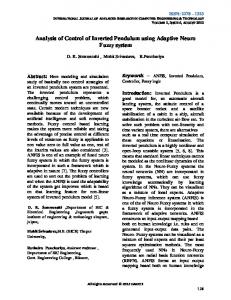
2. Inverted Pendulum System As shown in Figure 1, an IP system has a cart which can move horizontally. One end of the pendulum rod is connected to the centre of the upper surface of the cart which is called the pivot point while the other end is free to move in vertical plane (𝑥𝑧-plane). This pendulum rod is stable in extreme downwards position and known as normal pendulum. But when the pendulum rod remains in upright position, it is known as IP system. This is an unstable condition which needs a continuous balancing force (𝐹𝑥 ) on cart in order to remain upright. In Figure 1 horizontal force is used as control action to displace the pivot around 𝑥 axis and the total kinetic energy
𝑙 (m) 0.3
𝑔 (m/s2 ) 9.8
(𝐾) due to mass of the pivot (𝑀) in 𝑥 direction, mass of pendulum rod (𝑚) in 𝑥 and 𝑧 directions, and potential energy (𝑃) of the IP system [10] which are 1 1 𝐾 = 𝑀𝑥̇2 + 𝑚 (𝑥𝑝̇2 + 𝑧̇𝑝2 ) , 2 2
Figure 1: Structure of inverted pendulum.
studies [20–24], the PI𝜆 D𝜇 controller gives better outcomes than PID controller. Though there are some applications of PI𝜆 D𝜇 controller for IP system [25, 26], PI𝜆 D𝜇 controller has not received considerable attention for unstable systems similar to IP system. Hence, in the present work, fractional order PID controller is designed in time domain to control pendulum angle as well as cart position. Fractional order PID controller is challenging to design because of the use of fractional calculus with very complex calculations. Therefore, a direct approach is used for calculating the parameters of both fractional order PID controllers with the help of a multiobjective fitness function (the fitness function consists of the sum of integral squares of pendulum angle, cart position, and control voltage). The fitness function is minimized by running the model according to a particle swarm optimization (PSO) [27–29] program in MATLAB. PSO is used in this work as it provides greater convergence towards optimal values as compared to other optimization techniques and it has the simple algorithm. The rest of the paper is divided into the following sections. Section 2 gives a description of the inverted pendulum system and derivation of system equations in state space form. Section 3 describes the fractional calculus and structure of the PI𝜆 D𝜇 controller. Section 4 gives details about PSO. Section 5 gives a complete description of control strategy. Section 6 gives a comparison of the simulation results for PI𝜆 D𝜇 controller and PID controller with and without disturbances. The paper ends with the conclusions in Section 7, which is followed by the references.
𝑚 (Kg) 0.1
𝑃 = 𝑚𝑔𝑧𝑝 ,
(1)
where 𝑥𝑝 = 𝑥 + 𝑙 sin 𝜃,
𝑧𝑝 = 𝑧 + 𝑙 cos 𝜃
(2)
𝑙 = the distance from the pivot to the mass centre of the pendulum, (𝑥, 𝑧) = the position of the pivot in the 𝑥𝑜𝑧 coordinate, (𝑥,̇ 𝑧)̇ = the speed in the 𝑥𝑜𝑧 coordinate, (𝑥𝑝 , 𝑧𝑝 ) = the position in the 𝑥 𝑜 𝑧 coordinate, (𝑥𝑝̇ , 𝑧̇𝑝 ) = the speed in the 𝑥 𝑜 𝑧 coordinate, and 𝑔 = the acceleration constant due to gravity. It is assumed that the inertia of the pendulum is negligible. Numerical values of all the parameters of IP system are given in Table 1. The Lagrange’s equations of the IP system are given as follows: 𝜕𝐿 𝑑 𝜕𝐿 ( )− = 𝐹𝑥 , 𝑑𝑡 𝜕𝑥 𝜕𝑥
(3a)
𝑑 𝜕𝐿 𝜕𝐿 ( )− = 0, 𝑑𝑡 𝜕𝜃 𝜕𝜃
(3b)
where 𝐿 = 𝐾 − 𝑃. By putting the expression of 𝐿 in (3a) and (3b) and after solving it, Lagrange’s equations of the IP system can be expressed as (𝑀 + 𝑚) 𝑥̈ + 𝑚𝑙 cos 𝜃𝜃̈ − 𝑚𝑙 sin 𝜃𝜃2̇ = 𝐹𝑥 ,
(4a)
cos 𝜃𝑥̈ + 𝑙𝜃̈ − 𝑔 sin 𝜃 = 0,
(4b)
−0.5 ≤ 𝑥 ≤ 0.5.
(5)
where
According to (4a) and (4b), the state equations of the IP system can be expressed as
𝑥2̇ =
𝑥1̇ = 𝑥2 ,
(6a)
−𝑚𝑔 cos 𝑥3 sin 𝑥3 + 𝑚𝑙 sin 𝑥3 𝑥42 + 𝐹𝑥 + 𝑑1 , 𝑀 + 𝑚 sin2 𝑥3
(6b)
𝑥3̇ = 𝑥4 ,
(6c)
𝑥4̇ =
−𝑚𝑙 cos 𝑥3 sin 𝑥3 𝑥42 − cos 𝑥3 𝐹𝑥 𝑀𝑙 + 𝑚𝑙 sin2 𝑥3 (𝑀 + 𝑚) 𝑔 sin 𝑥3 + + 𝑑2 , 𝑀𝑙 + 𝑚𝑙 sin2 𝑥3
(6d)
Journal of Engineering
3 KD
s𝜇 E(s)
Proportional action
KP
Σ
+
+ +
KI
1/s𝜆
Integration
Derivative action
U(s)
Integral action
(0, 1) PI
(1, 1) PID
(0, 0) P
(1, 0) PD Derivative
Figure 2: FOPID controller structure.
Figure 3: Generalization of the PID controller.
where 𝑥1 = 𝑥, 𝑥2 = 𝑥,̇ 𝑥3̇ = 𝜃, 𝑥4 = 𝜃,̇ and 𝑑1 , 𝑑2 are the external disturbances. As it is known that IP system is a highly nonlinear and unstable system. Therefore, accurate modelling of a system having nonlinear dynamics cannot be obtained using standard linearization techniques. Hence, in this paper (6a), (6b), (6c), and (6d) are considered as it is without using any linearization technique.
3. Fractional Calculus and Fractional Order PID Controller 3.1. Fractional Calculus. Fractional calculus [16–18] is a branch of mathematics which deals with integration and differentiation operators that have fractional number powers. Though these types of operators are complex in nature as compared to integer order operators, they provide a generalization which also includes integer order operators. The three most frequently used definitions are RiemannLiouville, Gr¨unwald-Letnikov, and Caputo [22]. The most common definition is known as Riemann-Liouville: 𝛼 𝑎 𝐷𝑡 𝑓 (𝑡)
=
𝑛
𝑡
𝑓 (𝜏) 𝑑𝜏 1 𝑑 . ∫ 𝑛 ⌈(𝑛 − 𝛼) 𝑑𝑡 𝑎 (𝑡 − 𝜏)𝛼−𝑛+1
(7)
The second one is the Gr¨unwald-Letnikov given as (𝑡−𝑎)/ℎ
1 𝛼 ∑ (−1)𝑗 ( ) 𝑓 (𝑡 − 𝑗ℎ) , 𝑗 ℎ → 0 ℎ𝛼 𝑗=0
𝛼 𝑎 𝐷𝑡 𝑓 (𝑡) = lim
(8)
where ( 𝛼𝑗 ) = ⌈(𝛼 + 1)/⌈(𝑗 + 1)⌈(𝛼 − 𝑗 + 1). Finally, Caputo expression is defined as 𝛼 𝑎 𝐷𝑡 𝑓 (𝑡)
=
𝑡 𝑓𝑛 (𝜏) 𝑑𝜏 1 , ∫ ⌈(𝛼 − 𝑛) 𝑎 (𝑡 − 𝜏)𝛼−𝑛+1
(9)
where, 𝑛 − 1 < 𝛼 < 𝑛, 𝑛 is an integer number, 𝑎 is initial condition. 3.2. Fractional Order PID Controller. PID controller [30, 31] is one of the most extensively used controllers, but in the last two decades the advancement in fractional calculus has introduced the fractional order PID controller in control applications. PI𝜆 D𝜇 controller is a generalized form of PID controller. The PI𝜆 D𝜇 controller structure is shown in Figure 2, in which the introduction of two extra parameters 𝜆 and 𝜇
makes it complex as compared to PID controller because of introduction of fractional calculus in it. The differential equation of the PI𝜆 D𝜇 controller [23] is described as 𝑢 (𝑡) = 𝐾𝑃 𝑒 (𝑡) + 𝐾𝐼 𝐷−𝜆 𝑒 (𝑡) + 𝐾𝐷𝐷𝜇 𝑒 (𝑡) .
(10)
The generalization of PID controller is shown in Figure 3, which can be obtained using different values of 𝜆 and 𝜇 in (10). PID (𝜆 = 1, 𝜇 = 1), PI (𝜆 = 1, 𝜇 = 0), PD (𝜆 = 0, 𝜇 = 1), or P (𝜆 = 0, 𝜇 = 0) are the special cases of PI𝜆 D𝜇 controller. Taking Laplace transform of (10), the controller expression in s-domain is obtained as 𝐶 (𝑠) =
𝐾 𝑈 (𝑠) = 𝐾𝑃 + 𝜆𝐼 + 𝐾𝐷𝑠𝜇 . 𝐸 (𝑠) 𝑠
(11)
By putting 𝜆 = 𝜇 = 1 in (11), the expression of PID controller can be written as 𝐶 (𝑠) =
𝐾 𝑈 (𝑠) = 𝐾𝑃 + 𝐼 + 𝐾𝐷𝑠. 𝐸 (𝑠) 𝑠
(12)
Hence, in the present work PID controller is also studied along with the study of PI𝜆 D𝜇 controller. In addition, the performance comparisons with the PID controller based on the same design specifications to show that the PI𝜆 D𝜇 controller has better performance in terms of performances index are carried out. In (11), 𝑠𝜆 and 𝑠𝜇 have fractional orders which are not directly compatible with MATLAB and it becomes difficult to realize hardware of PI𝜆 D𝜇 controller. Therefore, there are several integer order approximation methods available for fractional order elements [32–34]. The 5th order Oustaloup’s integer order approximation [32] in the frequency range (10−2 , 102 ) rad/s is used in this work. In MATLAB fractional order PID controller is implemented using FOMCOM toolbox [35] where Oustaloup’s approximation is realized.
4. Particle Swarm Optimization While solving complex optimization problems having large search space the population based swarm intelligence method is the widely accepted alternatives to find the optimal solution. The particle swarm optimization (PSO) was first proposed by Kennedy and Eberhart [27]. The PSO method [27–29] is population based search techniques used for
4
Journal of Engineering Start
Initialized the particle position and velocity Iter = 1 fitness = fitnesspbest Iter = Iter +1
Evaluate the fitness
If fitnesspbest(i) < fitnesspbest (i − 1)
No
Yes No
pbest(i) = pbest(i)
pbest(i) = pbest(i − 1)
Evaluate gbest If fitnesspbest(iter) < fitnesspbest(iter−1)
Yes No
gbest(iter) = gbest(iter)
gbest(iter) = gbest(iter−1)
Update the velocity and position
If iter = itermax
Yes End
Figure 4: Flow diagram of basic PSO algorithm.
solving the optimization problems having a large search space. This technique mimics the behaviour of bird flocks and fish schools and their collision-free and synchronized moves. Individual bird or fish is known as particle in a PSO system and each particle has its position and velocity. Now particle moves in multidimensional search space according to its own experience and the experience of the neighbouring particles. During the movement in search space, the position and velocity of the particles are updated. There are three factors inertia, cognitive, and social upon which the velocity and position update of particles depend. The complete procedure
of PSO algorithm can be understood with the help of Figure 4 which indicates that the PSO algorithm has three steps: (1) to evaluate the fitness value of each particle, (2) to update individual best positions (pbest) and global best positions (gbest) according to best or minimum fitness values, (3) to update velocity and position of each particle in each iteration. The above steps are repeated until some stopping criteria are met.
Journal of Engineering
5
Form workspace
Reference r(t)
−
𝜇
PI𝜆 D2
+
+
𝜇
PI𝜆 D1
+
Control force, Fx u(t) Inverted pendulum system
Cart position x(t) Pendulum angle 𝜃(t)
Form workspace
W2 W1 W3
To workspace
+ +
+
Integrator
Figure 5: Basic block diagram of closed loop control system using two PI𝜆 D𝜇 controllers.
Position update equation is given by
Table 2: Parameters of fitness function. 𝑇 30
𝑤1 1
𝑤2 1
𝑤3 0.05
Table 3: Values of PSO parameters. PSO Parameters Number of particles Number of iterations 𝑐1 𝑐2 𝑊max 𝑊min 𝑅1 𝑅2
Values 10 25 2 2 0.9 0.1 0.1 0.1
Table 4: Range of controller parameters. Controller parameters 𝐾𝑃1 , 𝐾𝐼1 , 𝐾𝐷1 , −𝐾𝑃2 , −𝐾𝐼2 ,−𝐾𝐷2 𝜆 1 , 𝜇1 , 𝜆 2 , 𝜇2
𝑋𝑖𝑘+1 = 𝑋𝑖𝑘 + 𝑉𝑖𝑘+1 ,
(14)
where, 𝑘 = iteration number, 𝑉𝑖 = velocity of 𝑖th particle, 𝑊 = inertia weight factor, 𝑐1 , 𝑐2 = cognitive and social acceleration factors respectively, rand () = random numbers uniformly distributed in the range (0, 1) and 𝑋𝑖 = position of 𝑖th particle. The expression for 𝑊 is given by 𝑊 = 𝑊max − [
𝑊max − 𝑊min ] ∗ 𝑘, 𝑘max
(15)
where, 𝑊max , 𝑊min = maximum and minimum values of 𝑊 respectively, 𝑘max = maximum number of iterations.
5. PI𝜆 D𝜇 Controller Design Strategy The main objectives of controller design are as follows:
Range {0, 50} {0, 1}
(1) to stabilize the pendulum at its upright position, (2) to uphold the cart position at the origin, (3) tracking of desired position by pendulum cart,
The modified velocity and position of each particle can be calculated using the current velocity and position as follows: 𝑉𝑖 𝑘+1 = 𝑊 × 𝑉𝑖 𝑘 + 𝑐1 × rand () × (𝑝best ,𝑖 − 𝑋𝑖 𝑘 ) + 𝑐2 × rand () × (𝑔best ,𝑖 − 𝑋𝑖 𝑘 ) .
(13)
(4) to use minimum control effort required to control the pendulum angle and cart position. To achieve the abovementioned control objective two PI𝜆 D𝜇 controllers are used as shown in Figure 5. There are two feedback paths from the two outputs (pendulum angle and cart position) of the IP system and this feedback is given
6
Journal of Engineering Table 5: Values of controller parameters.
𝜇
to PI𝜆 D1 and PI𝜆 D2 . The output of each PI𝜆 D𝜇 is added and given as control input to the IP system. The fitness function 𝐽 to be minimized using PSO is given as 𝑇
𝐽 = ∫ [𝑤1 × 𝜃2 (𝑡) + 𝑤2 × 𝑥2 (𝑡) + 𝑤3 × 𝑢2 (𝑡)] 𝑑𝑡, 0
Angle (rad)
𝐾𝐷 3.1337 −1.8977 3.2143 −2.7675
𝜆 0.3579 0.4764 — —
𝜇 0.9038 0.8908 — —
where 𝜃(𝑡), 𝑥(𝑡), and 𝑢(𝑡) are pendulum angle, cart position, and control input, respectively, and 𝑤1 , 𝑤2 , and 𝑤3 are the weights to give equal weightage to all parameters. 𝑇 is the simulation time used for running model in SIMULINK. The fitness function given by (16) has three terms. The first term is the integral square of pendulum angle 𝜃(𝑡) which is used to stabilize pendulum angle. The second term is the integral square of cart position 𝑥(𝑡) which is used to stabilize cart position. Finally, the third term is the integral square of control input 𝑢(𝑡) which is used to minimize the required control force. Basic block diagram of closed loop control system as shown in Figure 5 is prepared in MATLAB/SIMULINK. This model has ten unknown parameters of two PI𝜆 D𝜇 controllers. These parameters are supplied by PSO program. Initially, parameters {𝐾𝑃1 , 𝐾𝐼1 , 𝐾𝐷1 , 𝜆 1 , 𝜇1 } and {𝐾𝑃2 , 𝐾𝐼2 , 𝐾𝐷2 , 𝜆 2 , 𝜇2 } are generated randomly but later in terms of pbest and gbest by updating the velocity and position of particles in each iteration. After generating controller parameters SIMULINK model is executed according to PSO program. When this model is executed, the fitness value (as given in (16)) of the SIMULINK model is saved in MATLAB workspace which is further utilized by PSO program for evaluating the minimum fitness value and corresponding controller parameters. The whole process is repeated until maximum number of iteration is reached. At the end of the process the values of parameters {𝐾𝑃1 , 𝐾𝐼1 , 𝐾𝐷1 , 𝜆 1 , 𝜇1 } and {𝐾𝑃2 , 𝐾𝐼2 , 𝐾𝐷2 , 𝜆 2 , 𝜇2 } are obtained which provides the desired performance of the IP system. Also, by considering 𝜆 = 𝜇 = 1 in both the PI𝜆 D𝜇 controllers, integer order PID controllers have been designed using the same specifications and comparative study has been carried out to show the validity of the proposed work.
𝐽 1.7131 1.8449
0.5
0 −0.5
0
2
4
6
(16)
8
10 12 Time (s)
14
16
18
20
14
16
18
20
14
16
18
20
(a) Position (m)
𝜇
𝐾𝐼 1.8185 −0.7636 1.2548 −1.3422
0.5
0 −0.5
0
2
4
6
8
10 12 Time (s)
(b) Control force Fx
𝐾𝑃 22.4734 −1.6749 23.9288 −2.6622
Controller PI𝜆 D𝜇 1 PI𝜆 D𝜇 2 PID1 PID2
20 10 0 −10
0
2
4
6
8
10
12
Time (s)
PID FOPID (c)
Figure 6: Stabilization of inverted pendulum (without disturbances 𝑑1 = 𝑑2 = 0).
6. Simulation and Results
in Figure 5 is executed by PSO program to obtain final parameters for both PI𝜆 D𝜇 and PID cases as given in Table 5. From Table 5 it can be concluded that based on the same specifications as given in Tables 2, 3, and 4, the fitness value 𝐽 using PI𝜆 D𝜇 controller is less as compared to PID controller. Controller parameters are calculated for stabilization control (without disturbances) but these values are also applicable in other cases. Simulation results, as shown in Figures 6–9, are obtained for stabilization and tracking control of IP system with and without disturbances. All the simulation results are particularized in next two subsections titled as stabilization and tracking control of IP system.
Parameters of (16) are given in Table 2. As 𝜃(𝑡) and 𝑥(𝑡) lie in the ranges {−0.5, 0.5} rad and {−0.5, 0.5} m, respectively, and are given equal weight but 𝑢(𝑡) is given very less weightage because of its high range {−20, 20} N. Therefore, all three terms of (16) are minimized equally. With the help of PSO parameters and controller parameters given in Tables 3 and 4, the SIMULINK model shown
6.1. Stabilization of Inverted Pendulum. For stabilization, reference cart position 𝑟(𝑡) = 0. In Figure 6, waveforms for 𝜃(𝑡), 𝑥(𝑡), and 𝑢(𝑡) settle to steady state approximately at the same time for both PI𝜆 D𝜇 controller and PID controller but during transient period PI𝜆 D𝜇 performs better than PID controller. Now to check the robustness of the designed
7 Angle (rad)
Angle (rad)
Journal of Engineering 0.4 0.2 0 −0.2
0
5
10
15
20 25 30 Time (s)
35
40
45
50
0.5
0 −0.5
0
10
20
30
10
15
20 25 30 Time (s)
35
40
45
50
Position (m)
Position (m)
0 5
0.6 0.4 0.2 0 −0.2 −0.4
0
10
20
30
0
5
10
15
20 25 30 Time (s)
70
80
90
100
40 50 60 Time (s)
70
80
90
100
70
80
90
100
(b)
35
40
45
50
Control force Fx
Control force Fx
(b) 20 10 0 −10
60
(a)
0.5
0
50
Time (s)
(a)
−0.5
40
15 10 5 0 −5 −10
0
PID FOPID
10
20
30
40 50 60 Time (s)
PID FOPID (c)
Figure 7: Stabilization of inverted pendulum (with disturbances 𝑑1 = 𝑑2 = 20 sin(20𝜋𝑡)).
Figure 8: Tracking of inverted pendulum (without disturbances 𝑑1 = 𝑑2 = 0).
7. Conclusion The stabilization and tracking control of IP system are attained successfully using PSO based direct tuning method.
Position (m)
6.2. Tracking Control of Inverted Pendulum. For tracking control, reference cart position 𝑟(𝑡) is considered as 0.3sin(0.05 𝜋t). Figure 8 shows the tracking control of IP system in which PI𝜆 D𝜇 controller for 𝜃(𝑡) provides less deviation in transient period and settles earlier to steady state as compared to PID controller. In Figure 8, both PI𝜆 D𝜇 and PID provide good tracking but in case of PI𝜆 D𝜇 , less control effort is required. In Figure 9, in the presence of disturbances, the PI𝜆 D𝜇 controller still outperforms PID controller and in PI𝜆 D𝜇 case less control effort is required. Simulation results shown in Figures 6–9 are furthermore important from real-time implementation viewpoint as in this simulation study practical conditions have also been taken into consideration.
0.6 0.4 0.2 0 −0.2 −0.4
0
10
20
30
40 50 60 Time (s)
70
80
90
100
70
80
90
100
70
80
90
100
(a)
0.5 0 −0.5
0
10
20
30
40 50 60 Time (s) (b)
Control force Fx
PI𝜆 D𝜇 and PID controllers, disturbances are 𝑑1 = 𝑑2 = 20 sin(20𝜋𝑡). Figure 7 shows the simulation results with disturbances which are still valid and proves the effectiveness of proposed PI𝜆 D𝜇 and PID controllers. The waveforms for 𝜃(𝑡) and 𝑢(𝑡) in Figure 7 in case of PI𝜆 D𝜇 are better than PID controller but, for 𝑥(𝑡) PID, perform slightly better than PI𝜆 D𝜇 controller. Also, in the case of control input 𝑢(𝑡) PI𝜆 D𝜇 provides less deviation during steady state as compared to PID controller.
Angle (rad)
(c)
15 10 5 0 −5 −10
0
10
20
30
40 50 60 Time (s)
PID FOPID (c)
Figure 9: Tracking of inverted pendulum (with disturbances 𝑑1 = 𝑑2 = 20 sin(20𝜋𝑡)).
8 The use of PSO technique for calculating controller parameters is very simple and provides good convergence towards optimal values. Two integer order PID controllers have also been designed by keeping the same specifications. A comparative study has been carried out and the obtained results are quite acceptable for both PI𝜆 D𝜇 and PID controllers but the PI𝜆 D𝜇 controller seems to be more robust. The PI𝜆 D𝜇 could be the good replacement for PID in the forthcoming years. The real time implementation of PI𝜆 D𝜇 controller might be the subject of further research.
Conflict of Interests The authors declare that there is no conflict of interests regarding the publication of this paper.
References [1] N. Muˇskinja and B. Tovornik, “Swinging up and stabilization of a real inverted pendulum,” IEEE Transactions on Industrial Electronics, vol. 53, no. 2, pp. 631–639, 2006. [2] T. Agustinah, A. Jazidie, and M. Nuh, “Hybrid fuzzy control for swinging up and stabilizing of the pendulum-cart system,” in Proceedings of the IEEE International Conference on Computer Science and Automation Engineering (CSAE ’11), vol. 4, pp. 109– 113, June 2011. ˚ om and K. Furuta, “Swinging up a pendulum by energy [3] K. J. Astr¨ control,” Automatica, vol. 36, no. 2, pp. 287–295, 2000. [4] A. Ghosh, T. R. Krishnan, and B. Subudhi, “Robust proportional-integral-derivative compensation of an inverted cart-pendulum system: an experimental study,” IET Control Theory & Applications, vol. 6, no. 8, pp. 1145–1152, 2012. [5] C.-E. Huang, D.-H. Li, and Y. Su, “Simulation and robustness studies on an inverted pendulum,” in Proceedings of the 30th Chinese Control Conference (CCC ’11), pp. 615–619, July 2011. [6] L. B. Prasad, B. Tyagi, and H. O. Gupta, “Modelling & simulation for optimal control of nonlinear inverted pendulum dynamical system using PID controller & LQR,” in Proceedings of the 6th Asia Modelling Symposium (AMS ’12), pp. 138–143, 2012. [7] M. R. Dastranj, M. Moghaddas, S. S. Afghu, and M. Rouhani, “PID control of inverted pendulum using particle swarm optimization (PSO) algorithm,” in Proceedings of the 3rd IEEE International Conference on Communication Software and Networks (ICCSN ’11), pp. 575–578, May 2011. [8] H. Lee, J. Lee, and J. Lee, “Hill climbing algorithm of an inverted pendulum,” in Proceedings of the IEEE International Symposium on Computational Intelligence in Robotics and Automation (CIRA ’09), pp. 574–579, December 2009. [9] S. Li, C. Huo, and Y. Liu, “Inverted pendulum system control by using modified PID neural network,” in Proceedings of the 3rd International Conference on Innovative Computing Information and Control (ICICIC ’08), pp. 1–426, June 2008. [10] J.-J. Wang, “Simulation studies of inverted pendulum based on PID controllers,” Simulation Modelling Practice and Theory, vol. 19, no. 1, pp. 440–449, 2011. [11] S. Jung, H.-T. Cho, and T. C. Hsia, “Neural network control for position tracking of a two-axis Inverted pendulum system: experimental studies,” IEEE Transactions on Neural Networks, vol. 18, no. 4, pp. 1042–1048, 2007.
Journal of Engineering [12] S. Omatu and S. Deris, “Stabilization of inverted pendulum by the genetic algorithm,” in Proceedings of the IEEE Conference on Emerging Technologies and Factory Automation (ETFA ’96), vol. 1, pp. 282–287, November 1996. [13] X.-H. Yang, H.-S. Liu, G.-P. Liu, and G.-F. Xiao, “Control experiment of the inverted pendulum using adaptive neuralfuzzy controller,” in Proceedings of the International Conference on Electrical and Control Engineering (ICECE ’10), pp. 629–632, June 2010. [14] M.-S. Park and D. Chwa, “Swing-up and stabilization control of inverted-pendulum systems via coupled sliding-mode control method,” IEEE Transactions on Industrial Electronics, vol. 56, no. 9, pp. 3541–3555, 2009. [15] R.-J. Wai, M.-A. Kuo, and J.-D. Lee, “Design of cascade adaptive fuzzy sliding-mode control for nonlinear two-axis invertedpendulum servomechanism,” IEEE Transactions on Fuzzy Systems, vol. 16, no. 5, pp. 1232–1244, 2008. [16] M. D. Ortigueira, Fractional Calculus for Scientists and Engineers, Springer, Berlin, Germany, 2011. [17] R. Caponetto, G. Dongola, L. Fortuna, and I. Petr´aˇs, Fractional Order Systems: Modeling and Control Applications, vol. 72 of World Scientific Series on Nonlinear Science Series A, World Scientific Publishing, Singapore, 2010. [18] D. Baleanu, K. Diethelm, E. Scalas, and J. J. Trujillo, Fractional Calculus Models and Numerical Methods, Series on Complexity, Nonlinearity and Chaos, World Scientific Publishing, Singapore, 2012. [19] D. Baleanu, J. H. Asad, and I. Petras, “Fractional-order twoelectric pendulum,” Romanian Reports in Physics, vol. 64, no. 4, pp. 907–914, 2012. [20] I. Podlubny, “Fractional-order systems and PI𝜆 D𝜇 controllers,” IEEE Transactions on Automatic Control, vol. 44, no. 1, pp. 208– 214, 1999. [21] I. Podlubny, I. Petr´aˇs, B. M. Vinagre, P. O’Leary, and L. Dorˇca´k, “Analogue realizations of fractional-order controllers,” Nonlinear Dynamics, vol. 29, no. 1–4, pp. 281–296, 2002. [22] C. Yeroglu and N. Tan, “Note on fractional-order proportionalintegral-differential controller design,” IET Control Theory and Applications, vol. 5, no. 17, pp. 1978–1989, 2011. [23] D. Maiti, A. Acharya, M. Chakraborty, A. Konar, and R. Janarthanan, “Tuning pid and PI𝜆 D𝛿 controllers using the integral time absolute error criterion,” in Proceedings of the 4th International Conference on Information and Automation for Sustainability (ICIAFS ’08), pp. 457–462, December 2008. [24] S. Das, S. Das, and A. Gupta, “Fractional order modeling of a PHWR under step-back condition and control of its global power with a robust PI𝜆 D𝜇 controller,” IEEE Transactions on Nuclear Science, vol. 58, no. 5, pp. 2431–2441, 2011. [25] F. Ikeda and S. Toyama, “Fractional derivative control designs by inhomogeneous sampling for systems with nonlinear elements,” in Proceedings of the SICE Annual Conference (SICE ’07), pp. 1224–1227, September 2007. [26] S. K. Mishra and D. Chandra, “Stabilization of inverted cartpendulum system using PI𝜆 D𝜇 controller: a frequency-domain approach,” Chinese Journal of Engineering, vol. 2013, Article ID 962401, 7 pages, 2013. [27] J. Kennedy and R. Eberhart, “Particle swarm optimization,” in Proceedings of the IEEE International Conference on Neural Networks, pp. 1942–1948, December 1995. [28] R. Eberhart, Y. Shi, and J. Kennedy, Swarm Intelligence, Morgan Kaufmann, San Mateo, Calif, USA, 2001.
Journal of Engineering [29] S. Yang, M. Wang, and L. Jiao, “A quantum particle swarm optimization,” in Proceedings of the IEEE Congress on Evolutionary Computation (CEC ’04), vol. 1, pp. 320–324, 2004. [30] K. Ogata, Modern Control Engineering, Prentice-Hall, Upper Saddle River, NJ, USA, 2002. ` om and T. H¨agglund, PID Controllers: Theory, Design [31] K. A. Astr¨ and Tuning, Instrument Society of America, Research Triangle Park, NC, USA, 1995. [32] A. Oustaloup, F. Levron, B. Mathieu, and F. M. Nanot, “Frequency-band complex noninteger differentiator: characterization and synthesis,” IEEE Transactions on Circuits and Systems I: Fundamental Theory and Applications, vol. 47, no. 1, pp. 25–39, 2000. [33] D. Val´erio and J. S. da Costa, “Time-domain implementation of fractional order controllers,” IEE Proceedings Control Theory and Applications, vol. 152, no. 5, pp. 539–552, 2005. [34] G. E. Carlson and C. A. Halijak, “Approximation of fractional capacitors (1/s) by a regular Newton process,” IRE Transactions on Circuit Theory, vol. 11, no. 2, pp. 210–213, 1964. [35] A. Tepljakov, E. Petlenkov, and J. Belikov, “FOMCON: fractional-order modeling and control toolbox for MATLAB,” in Proceedings of the 18th International Conference on Mixed Design of Integrated Circuits and Systems (MIXDES ’11), pp. 684–689, June 2011.
9
International Journal of
Rotating Machinery
Engineering Journal of
Hindawi Publishing Corporation http://www.hindawi.com
Volume 2014
The Scientific World Journal Hindawi Publishing Corporation http://www.hindawi.com
Volume 2014
International Journal of
Distributed Sensor Networks
Journal of
Sensors Hindawi Publishing Corporation http://www.hindawi.com
Volume 2014
Hindawi Publishing Corporation http://www.hindawi.com
Volume 2014
Hindawi Publishing Corporation http://www.hindawi.com
Volume 2014
Journal of
Control Science and Engineering
Advances in
Civil Engineering Hindawi Publishing Corporation http://www.hindawi.com
Hindawi Publishing Corporation http://www.hindawi.com
Volume 2014
Volume 2014
Submit your manuscripts at http://www.hindawi.com Journal of
Journal of
Electrical and Computer Engineering
Robotics Hindawi Publishing Corporation http://www.hindawi.com
Hindawi Publishing Corporation http://www.hindawi.com
Volume 2014
Volume 2014
VLSI Design Advances in OptoElectronics
International Journal of
Navigation and Observation Hindawi Publishing Corporation http://www.hindawi.com
Volume 2014
Hindawi Publishing Corporation http://www.hindawi.com
Hindawi Publishing Corporation http://www.hindawi.com
Chemical Engineering Hindawi Publishing Corporation http://www.hindawi.com
Volume 2014
Volume 2014
Active and Passive Electronic Components
Antennas and Propagation Hindawi Publishing Corporation http://www.hindawi.com
Aerospace Engineering
Hindawi Publishing Corporation http://www.hindawi.com
Volume 2014
Hindawi Publishing Corporation http://www.hindawi.com
Volume 2014
Volume 2014
International Journal of
International Journal of
International Journal of
Modelling & Simulation in Engineering
Volume 2014
Hindawi Publishing Corporation http://www.hindawi.com
Volume 2014
Shock and Vibration Hindawi Publishing Corporation http://www.hindawi.com
Volume 2014
Advances in
Acoustics and Vibration Hindawi Publishing Corporation http://www.hindawi.com
Volume 2014