Stable V/f Control System with Unity Power Factor for PMSM Drives Gheorghe-Daniel Andreescu*, Senior Member, IEEE, Cristina-Elena Coman*, Ana Moldovan**, Ion Boldea**, Fellow, IEEE *
Dept. of Automation and Applied Informatics, “Politehnica” University of Timisoara, 2 Vasile Parvan Blvd., Romania ** Dept. of Electrical Engineering, “Politehnica” University of Timisoara, 2 Vasile Parvan Blvd., Romania E-mail:
[email protected],
[email protected],
[email protected],
[email protected] Abstract−This paper develops a scalar V/f control system for permanent magnet synchronous motor (PMSM) drives with two stabilizing feedback corrections: i) a voltage-vector speed correction using active power variation, in action only in transient states, and ii) a voltage amplitude correction based on unity power-factor regulation loop, employing reactive power. Motor / generator operating mode is allowed using the active power sign information. The proposed solution, inherent for sensorless control, is simple, requires reduced computation time, thus it is competitive for very-high variable speed PMSM drives like fans, pumps, micro gas-turbine generators, etc. Significant simulation results prove good performance for the proposed control structure in steady and transient states, for fast speed references and step rated load torque. Index terms−active/reactive power, power factor, permanent magnet synchronous motor (PMSM), scalar control, V/f control.
I.
INTRODUCTION
Permanent magnet synchronous motor (PMSM) drives are used on large scale for industrial applications having the following advantages: high efficiency, high power density and high dynamic response [1]. The control methods applied in PMSM drive systems are: i) vector control, i.e., current-vector control, field oriented control, direct torque and flux control, with high dynamic performance, and ii) scalar control, usually standard V/f control or V/f control with stabilizing corrections, with simple implementations, but with medium, even low dynamic responses. In the last decade, sensorless control methods (without rotor position-speed transducers) are widely developed in order: to increase the performance per cost factor and reliability; to reduce the cost, mass, volume; and to eliminate the disturbances on direct measurement, transducer vibrations with problems at very high speed and transducer failures. The observer techniques are employed to estimate the rotor position and speed using only current sensors and eventually the inverter input dc voltage (Vdc) sensor. The sensorless methods are divided into three classes [1]: (i) Methods based on the fundamental machine model (emf estimation), with model parameter dependence, working at speed greater than nx10 rpm; (ii) Injection methods, which inject additional sinusoidal or square waves voltage with high frequency, exploiting machine anisotropies, with robustness to parameter variations. They are recommended at low speed including
978-1-4673-1653-8/12/$31.00 '2012 IEEE
zero speed; iii) Hybrid methods for wide speed range, that combine the advantage of the i) and ii) methods. The implementations of vector control systems with these sensorless control methods require computational effort with sampling period of 50-100 μs in industrial applications. On the other hand, scalar V/f control for PMSM drives is an inherent motion sensorless control method, using two (even one) current sensors, with simple implementations, requiring short sampling period. Usually, V/f control methods do not use rotation operators, nor control loops for speed, currents, torque or flux. They are recommended for variable speed drives from medium to very high-speed (nx100 krpm), in industrial applications like fans, pumps, turbo blowers, compressors, micro gas-turbine generators [2], [3]. A good comparison between the V/f control and sensorless vector control for PMSM drives, specifying recommended applications, is given in [4]. The basic V/f control method could present instability with oscillatory responses, even losing synchronism [5] when the speed reference or the load-torque changes. There are few solutions to stabilize the system using feedback corrections for the speed and amplitude references of the voltage vector. An outstanding idea for V/f system stabilization is to employ: i) the active power variation for voltage vector speed correction, with stability proof using full small-signal dynamics model, and ii) the voltage amplitude command calculated by using measured phase currents [5], [6]. The speed correction (i) has become a basic method, widely exploited in many research references in stable V/f control. An optimal V/f control of high speed PMSMs, using speed correction [5] and voltage reference selected from: I-f control, V/f control or voltage optimization control, is presented in [7] A voltage reference correction based on the reactive power regulation under maximum torque per ampere (MTPA) performance, and speed correction [5] is used in [8]. Another solution [9] uses a control loop for zero interior reactive power (equivalent to id* = 0) with action on two stabilizing corrections for voltage amplitude and phase. A novel solution with two stabilizing loops, i.e., a rotor speed loop for voltage angle correction, and an active flux loop for voltage amplitude correction, based on the active flux concept is presented in [10]. Flux weakening and MTPA conditions are built in. A new method to stabilize the V/f control for sinusoidal wave drives, based on power factor control under MTPA
432
optimization for voltage amplitude reference, without speed correction, and employing a single current transducer on dc link circuit, is presented in [11], [12]. An improved V/f control solution for wide speed range, with one current phase sensor, uses the speed correction [5] and the voltage correction based on the power factor control with optimized references by: MTPA [13], flux weakening, or maximum torque per voltage [14] according to the motor operating point, with look-up table based implementation. The present paper proposes a stable V/f control structure with two stabilizing feedback corrections: i) a voltage-vector speed stabilizing correction based on active power variation, working only in transitory-state, and ii) a voltage amplitude correction based on an unity power-factor regulation loop, using reactive power. Only two phase current sensors are employed. Motor / generator operating mode is allowed using active power sign information. The significant simulation results prove good performance in steady and transient states, for fast speed references and step rated load torque. II. PROPOSED STABLE V/F CONTROL SYSTEM A. Basic V/f Control Method The PMSM mathematical model in dq rotor reference frame is given by:
3⁄2
ω
(1)
⁄
ω λPM
(2)
λPM
ω ⁄ θ⁄
⁄
(3) ω , ω
ω,
ω/
A basic V/f control method is highlighted in Fig. 1 by the uses a ramp following elements. The speed reference (ω limiter to limit the angular acceleration. The voltage is proportional with the speed reference ω amplitude λPM · ω from (1, 2), with under no load condition: offset for a correct start-up. The voltage vector position (θ is mainly obtained by integrating the speed reference ω . A ,θ to αβ stator reference , polar transformation is used to generate the voltage vector for voltage source inverter (INV) command. reference B. Voltage Vector Speed Correction The basic V/f control method usually presents instability, i.e., oscillatory responses, even loss of synchronism [5] when the speed or load-torque reference changes. θ / in αβ From Fig. 2, the voltage vector speed ω stator reference frame is given by: ω
where , , , are the stator voltage and current are d-q axis components, Rs is the stator resistance, , inductances, ω , θ are the electrical rotor speed and position, is ω is the mechanical rotor speed, λPM is the PM flux, is the load torque, J is the the electromagnetic torque, motor inertia, B is the viscous friction coefficient and p is the number of pole pair. The proposed V/f control structure with two stabilizing feedback corrections, i.e., speed correction and voltage correction, for PMSM drives is shown in Fig. 1.
ω ,
(6)
where ω is the voltage vector speed in dq reference frame. const., therefore ω ω , that is the In steady state θ synchronism condition. On the other hand, in transient state ω and in some circumstances the motor loses the ω synchronism. In order to stabilize the system, a voltage vector speed correction is used. The main idea is as follows: in transient state when the rotor speed ω tends to oscillate around ω with a rotor speed variation Δω , the stator voltage speed reference ω will be modified with the same variation in order to maintain the synchronism:
(4) (5)
ω
ω
ω
Δω .
(7)
Taking into account that V/f control is a sensorless control (without rotor position/speed sensor), the speed variation Δω cannot be directly measured, thus Δω will be estimated. Using signal variations, for a constant vs(vd, vq), if the load 0 then Δω 0 from (4), then ∆ 0 torque rises, ∆ from (2) and ∆ 0 from (3), therefore, summarizing Δω ~ ∆ . On the other hand, ∆ ~∆ / , where is the instantaneous active power calculated by using the measured , and the reference voltage , ), neglecting current voltage drops on the nonlinear inverter model:
Fig. 1. Proposed stable V/f control structure for PMSM drives with two stabilizing feedback corrections.
433
3⁄2
.
Fig. 2. Vectors vs and is in voltage-vector reference frame.
(8)
The ∆ variation is extracted from P using a high-pass filter (HPF) with the transfer function H(s) = Ts / (Ts+1),
(9)
where the time constant T is experimentally chosen depending on rotor speed oscillations. In conclusion, the estimation of the rotor speed variation Δω , presented in Fig. 1, is given by: ⁄ω ·
Δω
,
(10)
where K > 0 is a gain experimentally obtained. Note that the speed correction Δω occurs only in transient state. This voltage vector speed correction increases the system damping factor which leads to a rapid reduction of speed oscillations. The proposed structure of voltage vector speed correction Δω (Fig. 1) is similarly to [5], with the remark that the way to find this structure is a novel one, straightforward, taking into account physical explanations. C. Voltage Amplitude Correction In the scalar V/f control, the voltage vector reference frame dvqv is naturally used (Fig. 2), with the dv axis oriented along . In this new reference frame, the voltage vector is controlled by the voltage the current vector amplitude , where φ is the angle between voltage and current vectors, i.e., the power factor angle. In current-vector control methods of PMSMs, current vector reference is provided in dq rotor reference frame to obtain the required electromagnetic torque. There are optimization criteria to generate in vector control [15], [16] which can be transposed to find optimal power factor angle reference : • unity power factor ( 1) control method; • maximum torque per ampere (MTPA) control method; • constant flux-linkage control method; • flux weakening, maximum torque per voltage [14]. In this paper the unity power-factor control method is used 0. by employing a power factor angle control loop with φ The feedback angle φ can be calculated using different methods based on: i) zero-crossing or the peak values detection of the phase voltage and current in a half period, with sensibility to noises in current waveforms, ii) average computation using the phase voltage and current in a half period [11], both methods using one current sensor, and iii) instantaneous φ estimation, employing the instantaneous active and/or reactive power that uses two current sensors. The 3rd method is selected for φ estimation by computing the instantaneous reactive power Q (11) and the active power , ) and the P (8) by using the reference voltages , : measured currents 3 ⁄2 The
.
φ
2 ⁄ 3
,
(12)
φ
2 ⁄ 3
,
(13)
. φ
2
,
(14) .
For φ estimation is recommended (12), that has monotony within – ⁄2 , ⁄2 , or better (15) with extended monotony within – , , both centered in 0. To reduce computational effort in (12), the approximation φ φ is used. For the power-factor angle control loop, a proportionalintegral (PI) controller with 1 1/ is chosen, with the time constant Ti designed close to the electrical time constant Lq /Rs. The trial and error method is employed for controller fine tuning. D. Motor / Generator Operating Mode Selection In the motor mode (MM), the rotor speed ω and the electromagnetic torque Te have the same sign: ω 0, while in the generator mode (GM) ω and Te have opposite sign: ω 0. In Fig. 3, for ω 0, the vectors associated to MM are illustrated by red color (φ 0 , while for GM, green color is used (φ 0 . For the same electromagnetic torque absolute value, the relation between φMM and φGM is given by: φGM
(15)
π
φMM
(16)
The selection of the motor/generator operating mode is given by the for ω 0. For unity power factor φMM 0 and φGM π, from (16). Thus, in Fig. 1, the reference angle φ is changed from 0 to -π by to select the specific operating mode. The proposed V/f sensorless control structure for PMSM (Fig. 1) mainly employs in implementation the following elements: PI controller, HPF (9), LPF, active power (8) and reactive power (13) computations with atan (15) table for φ estimation and polar to αβ operator with sin-cos table. The simpler sensor vector control structure for PMSM with id*=0 contains: 3 PI controllers, LPF for speed reference, emf compensation block, 2 abc-dq rotator operators with sin-cos table and position transducer. Comparatively, the proposed V/f sensorless control structure requires rather less computation effort, and does not use position transducer. III. SIMULATION RESULTS
(11)
angle can be estimated in different ways:
where
Fig. 3. Motor/generator operating mode: vs, is and λs vectors.
To validate the performances of the proposed V/f control system, extensive simulations were performed using the MATLAB & Simulink package with h=100 μs sampling rate, that is commonly used in industrial drives. The PMSM parameters are presented in Table I and the control system parameters from Fig. 1 are presented in Table II of Appendix. Three case scenarios were created to test dynamic performances of the proposed solution.
434
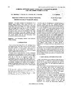
Fig. 5. Transient responses for ramp startup to 300 rad/s, followed by a step rated load torque TL=12 Nm applied and removed: estimated speed, id, iq currents without activating the braking generator mode (GM).
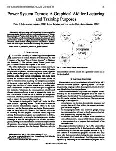
Fig. 4. Transient responses for ramp startup to 300 rad/s, followed by a step rated load torque TL=12 Nm applied and removed: estimated speed, id, iq currents, torque, speed correction, voltage correction and power factor angle.
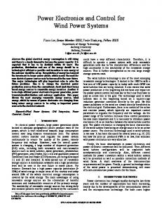
Scenario no. 1 (Fig. 4) illustrates the transient responses for startup in fast ramp reference speed with the acceleration εr* = 1000 rad/s2 and speed ωr* from 0 to 300 rad/s, with a low load torque TL0 = 0.5 Nm. At t1 = 0.7 s, a step rated load torque TL1 = 12 Nm is applied, and at t2 = 1.5 s the load torque is reduced to TL0. The speed ω succeeds the reference speed ω , having an undershoot and overshoot of 70 rad/s at step rated load torque applied / removed and good quick torque response. The electromagnetic torque Te is proportional with iq current, and 0 for motor mode (MM), like in vector control. The braking generator mode (GM) takes place at 0.35 s and 1.5 s 0, when the reference angle φ steps from 0 to -π for rad. In this time interval, the calculated angle φ oscillates from -π to π because of the discontinuity of the atan2 function. The speed correction follows the torque variation and the voltage correction is in accordance with desired theoretical variations. In steady state, the power factor regulation loop leads φ to 0. In Fig. 5, the current components variations are highlighted in the conditions of scenario 1, but without switching to 0, the braking generator mode (GM). Note that when responses are oscillatory and has twice bigger and overshoot comparing with the case when GM is activated. Scenario no. 2 (Fig. 6) illustrates the transient responses for ramp speed variations ω with 100 rad/s steps, increasing up to 300 rad/s and decreasing down to 5 rad/s for a constant load torque TL=2 Nm. The speed response ω matches the speed reference ω current is negative during this with small overshoots. The experiment, with a fast torque response. At start-up and 0 for a short time, while the during decreasing speed, operating mode changes to breaking generator mode (GM) as seen in the power factor angle variations. The speed correction is active only in the transient regime, and together with the voltage correction help to stabilize the system.
435
Fig. 6. Transient responses for cascade ramp speed increased to 300 rad/s, decreased to 5 rad/s with TL=2 Nm: estimated speed, id, iq currents, torque, speed correction, voltage correction and power factor angle.
Fig. 7. Transient responses at 200 rad/s for slow ramp of load torque from 0.5 to 12 Nm followed by step discharge of 0.5 Nm: estimated speed, id, iq currents, torque, speed correction, voltage correction and power factor angle.
436
APPENDIX
Scenario no. 3 (Fig. 7) illustrates the transient responses for slow ramp reference load torque from 0.5 to 12 Nm in 0.5 s, followed by a step load discharged to 0.5 Nm. During the period of 0.5 s, when the ramp load is applied, 2 rad/s the HPF generates a small speed correction of ∆ω because the active power P is in transient state (see Fig. 1). 0, the operating mode When the load is discharged and is switched to GM, which is shown in the power factor angle variation. In conclusion, the proposed V/f control structure with two stabilizing feedback corrections presents good dynamic stability (comparable with vector control), for fast ramp 0, reference speed and step load rated torque. Note that like in vector control, excepting small time periods especially for MM to GM changeover and back.
TABLE I PMSM PARAMETERS 600 rad/s Rated mechanical speed (ωrn) Rated torque (Ten) 12 Nm Number of pole pairs (p) 4 Stator resistance (Rs) 0.6 Ω d-axis inductance (Ld) 4.1 mH q-axis inductance (Lq) 8.2 mH Permanent magnet flux (λPM) 0.2 Wb Motor inertia (J) 0.005 kgm2 Viscous friction coefficient (B) 0.0015 Nms/rad TABLE II CONTROL SYSTEM PARAMETERS 120 V Maximum voltage (V*) Initial voltage (V0*) 2V Speed correction gain (K) 20 Nms/rad HPF time constant (T) 10 ms 0.5 V/rad PI proportional constant ( ) PI time constant (Ti) 20 ms LPF time constant (Tf) 10 ms
IV. CONCLUSION This paper develops a stable V/f control structure with unity power factor, having good performance and low computation effort, recommended for (very) high-speed PMSM drives in applications like fans, pumps, micro gas turbine generators where computation time is quite critical. The proposed solution, inherent for motion sensorless control of PMSM drives, employs two stabilizing feedback corrections: i) a voltage vector speed correction using active power variation working in transitory state, and ii) a voltage amplitude correction based on unity power factor regulation loop using reactive power, with motor/generator operating mode selected by the active power sign. Simulation results, in significant test scenarios, validate the proposed solution with good performances in static/dynamic regimes, for fast speed variations and step rated load torque. The main paper contributions are: • Novel straightforward way to obtain the voltage vector speed correction structure based on physical insightful; • Voltage amplitude correction employing unity power factor regulation loop; • Motor/generator operating mode selected by active power sign that modifies the power factor angle reference; • Estimation of the instantaneous power factor angle using active/reactive power; • Good simulation results that validate the proposed V/f control structure in wide speed range and step rated load torque, in motor/generator operating mode; • Low computation effort, suitable for real time implementation with small sample rate (nx10 μs), fitted for very high-speed PMSM drives applications as fans, pumps, micro gas turbine generators, etc. ACKNOWLEDGMENT This work was partially supported by the strategic grants POSDRU/107/1.5/S/77265 (2010) and POSDRU/6/1.5/S/13 (2008), within the Sectoral Operational Program for Human Resources Development 2007-2013, Romania, co-financed by the European Social Fund - Investing in people.
REFERENCES [1]
S.-K. Sul, Control of Electric Machine Drive Systems, New Jersey: IEEE Press, John Wiley & Sons, Inc., 2011. [2] L. Zhao, C.H. Ham, Q. Han, T.X. Wu, L. Zheng, K.B. Sundaram, J. Kapat, and L. Chow, “Design of optimal digital controller for stable super-high-speed permanent-magnet synchronous motor,” IEE Proceedings -Electric Power Applications, vol. 153, no. 2, pp. 213-218, Mar. 2006. [3] M. Morimoto, K. Aiba, T. Sakurai, A. Hoshino, and M. Fujiwara, “Position sensorless starting of super high-speed PM generator for micro gas turbine,” IEEE Trans. on Industrial Electronics, vol. 53, no. 2, pp. 415-420, Apr. 2006. [4] J.-I. Itoh, N. Nomura, and H. Ohsawa, “A comparison between V/f control and position-sensorless vector control for the permanent magnet synchronous motor,” in Proc. Power Conversion Conf., (PCC 2002), Osaka, Japan, Apr. 2002, vol. 3, pp. 1310-1315. [5] P.D.C. Perera, F. Blaabjerg, J.K. Pedersen, and P. Thogersen, “A sensorless, stable V/f control method for permanent-magnet synchronous motor drives,” IEEE Trans. on Industry Applications, vol. 39, no. 3, pp. 783-791, May/Jun. 2003. [6] D. Montesinos-Miracle, P.D.C. Perera, S. Galceran-Arellano, and F. Blaabjerg, “Sensorless V/f control of permanent magnet synchronous motors,” in Motion Control (Book Ch. 23), F. Casolo, Ed. InTech, Croatia, 2010, pp. 439-458. [7] T. Halkosaari, “Optimal U/f-control of high speed permanent magnet motors,” in Proc. IEEE Int. Symposium on Industrial Electronics (ISIE 2006), Montreal, Canada, Jul. 2006, vol. 3, pp. 2303-2308. [8] Shinn-Ming Sue, Tsai-Wang Hung, Jenn-Horng Liaw, Yen-Fang Li, and Chen-Yu Sun, “A new MTPA control strategy for sensorless V/f controlled PMSM drives,” in Proc. 6th IEEE Conf. on Industrial Electronics and Applications (ICIEA 2011), Beijing, China, Jun. 2011, pp. 1840-1844. [9] R. Ancuţi, I. Boldea, and G.-D. Andreescu, “Sensorless V/f control of high-speed surface permanent magnet synchronous motor drives with two novel stabilising loops for fast dynamics and robustness,” IET Electric Power Applications, vol. 4, no. 3, pp. 149-157, Mar. 2010. [10] I. Boldea, A. Moldovan, V. Schramel-Coroban, G.-D. Andreescu, and L. Tutelea, “A class of fast dynamics V/f sensorless AC general drives with PM-RSM as a case study,” in Proc. 12th Int. Conf. on Optimization of Electrical and Electronic Equipment (OPTIM 2010), Braşov, România, May 2010, pp. 453-459. [11] M. Matsushita, H. Kameyama, Y. Ikeboh, and S. Morimoto, “Sinewave drive for PM motor controlling phase difference between voltage and current by detecting inverter bus current,” IEEE Trans. on Industry Applications, vol. 45, no. 4, pp. 1294-1300, Jul.-Aug. 2009.
437
[12] M. Matsushita, H. Kameyama, Y. Ikeboh, and S. Morimoto, “Stabilization control of sensorless sinusoidal wave drive for control of power factor of PM motor,” in Proc. Int. Conf. on Electrical Machines and Systems (ICEMS 2009), Tokyo, Japan, Nov. 2009, pp. 1-5. [13] M. Cacciato, A. Consoli, G. Scarcella, and G. Scelba, “A novel efficiency optimization scalar control technique for industrial IPMSM drives,” in Proc. 2010 IEEE Int. Symposium on Industrial Electronics (ISIE 2010), Bari, Italy, Jul. 2010, pp. 1181-1186. [14] A. Consoli, G. Scarcella, G. Scelba, and M. Cacciato, “Range extended efficiency optimization technique for scalar IPMSM drives,” in Proc.
14th Int. Power Electronics and Motion Control Conf. (EPE/PEMC 2010), Orhid, Macedonia, Sep. 2010, pp. S10-7-S10-14. [15] S. Morimoto, Y. Takeda, and T. Hirasa, “Current phase control methods for permanent magnet synchronous motors,” IEEE Trans. on Power Electronics, vol. 5, no. 2, pp. 133-139, Apr. 1990. [16] S. Morimoto, Y. Takeda, T. Hirasa, and K. Taniguchi, “Expansion of operating limits for permanent magnet motor by current vector control considering inverter capacity,” IEEE Trans. on Industry Applications, vol. 26, no. 5, pp. 866-871, Sep./Oct. 1990.
438